
Related Manuals for Stryker GLIDE 3061


Summary of Contents for Stryker GLIDE 3061
- Page 1 STRYKER GLIDE™ Lateral Patient Transfer System Model 3061 Operations/Maintenance Manual For Parts or Technical Assistance: USA: 1-800-327-0770 (option 2) Canada: 1-888-233-6888 2008/05 3061-009-001 REV A www.stryker.com...
-
Page 3: Table Of Contents
EMC Information ................28 www.stryker.com... -
Page 4: Introduction
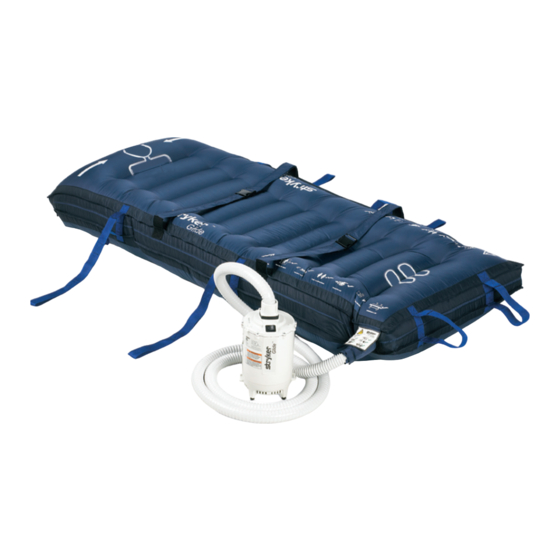
The continuous air flow helps to reduce friction between the sleep surface and the GLIDE™ Matt allowing the operator to transfer the patient with ease. ProdUct IllUstratIon Stryker GLIDE™ Matt Patient Centering Straps Extended Pull... -
Page 5: Specifications
3.9 kg Duty Cycle 30 seconds ON / 1 minute OFF for 5 cycles followed by a 30 minute rest period. IEC/EN 60601-1 UL 60601-1 Product Compliance CAN/CSA-C22.2 No 601.1-M90 IEC/EN 60601-1-2:2001 Return To Table of Contents www.stryker.com 3061-009-001 REV A... -
Page 6: Warning / Caution / Note Definition
Atmospheric Pressure 700 hPa 500 hPa Stryker reserves the right to change specifications without notice. Specifications listed are approximate and may vary slightly from unit to unit or by power supply fluctuations. WarnInG / CaUTIOn / nOTE DEfInITIOn The words WARNING, CAUTION, and NOTE carry special meanings and should be carefully reviewed. -
Page 7: Symbols
Patient Support Platform siderails Patient Support Platform brakes must be in the “UP” position prior must be set to “ON” prior to starting to starting inflation process or inflation process. transferring a patient. Return To Table of Contents www.stryker.com 3061-009-001 REV A... -
Page 8: Summary Of Safety Precautions
The GLIDE™ can only be used on transfers between fixed patient support surfaces. Mobile surfaces need the brakes applied to make them a fixed surface. • Stow accessories such as the Stryker pop-up push handles before beginning a transfer using the GLIDE™. Return To Table of Contents 3061-009-001 REV A... - Page 9 • Maximum leakage current shall not exceed 100 micro amps on air supply enclosure and 100 micro amps on air mattress. • No automatic pressure relief exists on device. Return To Table of Contents www.stryker.com 3061-009-001 REV A...
-
Page 10: Operation Guide
Center the patient on the mattress. Attach the two patient centering straps in gentle contact with the patient. Straps need not be tight. note: Do not pull on the patient centering straps to transfer the patient. Return To Table of Contents 3061-009-001 REV A www.stryker.com... -
Page 11: Connecting The Air Supply
1.3 figure 1.4 Using the air hose retention straps, secure the air hose to the mattress. note: The air supply unit can remain in the roller bag if needed. Return To Table of Contents www.stryker.com 3061-009-001 REV A... -
Page 12: Transfer Of Patient From Stretcher To Bed
Turn “OFF” air supply by pressing the switch to the “O” position (Figure 2). Unplug power cord from wall and air supply. WarnInG Never leave patient unattended when mattress is inflated and air supply is on. 3061-009-001 REV A www.stryker.com... -
Page 13: Preventative Maintenance
_____ Plastic on the blower assembly is not damaged. _____ Mattress holds air and all straps are intact. _____ Current leakage not to exceed 100 micro amps. Unit Serial Number: Completed by: _______________________________________ Date: _________________ Return To Table of Contents www.stryker.com 3061-009-001 REV A... -
Page 14: Cleaning
10% bleach and water solution. Water temperature should not exceed 150 degrees Fahrenheit. • The Protective Sheet should be air dried if possible. Machine drying can be performed as long as the maximum air or drum temperature does not exceed 120 degrees Fahrenheit. Return To Table of Contents 3061-009-001 REV A www.stryker.com... -
Page 15: Routine Care: Blower Unit
CDC (US Department of Health and Human Services, February 1989). Weaker dilutions, e.g. 1:100 may be used but may not be in accordance with CDC recommendations. note: always wash hands thoroughly after cleaning the mattress, protective sheet or blower unit. Return To Table of Contents www.stryker.com 3061-009-001 REV A... -
Page 16: Troubleshooting Guide
If the air volume diminished, check the air inlet on the lower housing for restrictions and repair. ii. If the there was no restriction in the lower housing, replace the blower assembly. Return To Table of Contents 3061-009-001 REV A www.stryker.com... -
Page 17: Service Information
Power cord connections are on the Off (O) side of the switch. Blower assembly connections are on the On (1) side of the switch. note: Do not overtighten the screws. Return To Table of Contents www.stryker.com 3061-009-001 REV A... -
Page 18: Upper Housing Replacement
Remove the blower assembly by grasping the blower assembly wire harness and lifting straight up and out of the main housing assembly. Install the new blower assembly. Install new wire tie. Repeat the above steps in reverse order to reassemble. nOTE: Do not overtighten the screws. Return To Table of Contents 3061-009-001 REV A www.stryker.com... -
Page 19: Quick Reference Replacement Parts List
Parts List note The parts and accessories listed on this page are all currently available for purchase. Please call Stryker Customer Service (800)-327-0770 (Option 2). 3060-000-028 rEPLaCEMEnT ParT LIST (rEGULar) Part name Part number Air Mattress Assembly (includes Protective Sheet) -
Page 20: Blower Unit Assembly, Standard - 3060-400-110
Blower Unit assembly, Standard - 3060-400-110 Assembly Part Number: 3060-001-210 (reference only) Return To Table of Contents 3061-009-001 REV A www.stryker.com... - Page 21 Power Cord Assembly 3060-001-804 Blower Assembly 3060-001-125 Blower Base with Feet 3060-009-139 Spec Label 3060-009-153 Caution Label 3060-009-158 Instruction Label 3060-009-159 Serial Number Label 3060-009-161 Stryker Glide™ Blower Label 3060-001-169 Strain Relief Retainer Return To Table of Contents www.stryker.com 3061-009-001 REV A...
-
Page 22: Blower Base With Feet - 3060-001-125
Blower Base with feet - 3060-001-125 Item Part no. Part name qty. 0023-190-000 Phillips Head Truss Screw 3060-001-124 Blower Base 3060-008-003 Blower Base Bumper Return To Table of Contents 3061-009-001 REV A www.stryker.com... -
Page 23: Hose Assembly, Standard - 3060-001-127
ParTS nOT SOLD SEParaTELy. Item Part no. Part name qty. 3060-001-128 Hose, Standard 3060-001-129 Hose End Assembly 3060-001-137 Hose/Mattress Coupling 3060-001-131 Hose Coupling, Matt 3060-001-132 Hose Retainer Bracket 3060-001-133 Hose Gasket Return To Table of Contents www.stryker.com 3061-009-001 REV A... -
Page 24: Hose Assembly, Optional 25'- 3060-045-002
ParTS nOT SOLD SEParaTELy. Item Part no. Part name qty. 3060-045-003 Hose, 25’ 3060-001-129 Hose End Assembly 3060-001-137 Hose/Mattress Coupling 3060-001-131 Hose Coupling, Matt 3060-001-132 Hose Retainer Bracket 3060-001-133 Hose Gasket Return To Table of Contents 3061-009-001 REV A www.stryker.com... -
Page 25: Mattress Assemblies
Mattress assemblies 28” regular - 3061-110-028 (reference only) 32” Large - 3061-110-032 (reference only) 32” 28” 46” Bariatric - 3061-110-046 (reference only) 46” Return To Table of Contents www.stryker.com 3061-009-001 REV A... -
Page 26: Tote Assembly - 3060-001-041
Tote assembly - 3060-001-041 Return To Table of Contents 3061-009-001 REV A www.stryker.com... -
Page 27: Warranty
Stryker, found to be defective. If requested by Stryker, products or parts for which a warranty claim is made shall be returned prepaid to the factory. -
Page 28: Emc Information
IEC 61000-4-8 characteristic typical location in a typical commercial and/or hospital environment. Note: U is the a.c. mains voltage prior to applications of the test level. Return To Table of Contents 3061-009-001 REV A www.stryker.com... - Page 29 At 80 MHz and 800 MHz, the separation distance for the higher frequency range applies. nOTE 2 These guidelines may not apply in all situations. Electromagnetic propagation is affected by absorption and reflection from structures, objects and people. Return To Table of Contents www.stryker.com 3061-009-001 REV A...
- Page 30 GLIDE™ should be observed to verify normal operation. If abnormal performance is observed, additional measures may be necessary, such as reorienting or relocating the GLIDE™. Over the frequency range 150 kHz to 80 MHz, field strengths are less than 3 V/m. Return To Table of Contents 3061-009-001 REV A www.stryker.com...
- Page 31 Class A CISPR 11 low voltage power supply network that supplies buildings used for domestic purposes. Harmonic Emissions Class A IEC 61000-3-2 Voltage Fluctuations Flicker Emissions Complies IEC 6100-3-3 Return To Table of Contents www.stryker.com 3061-009-001 REV A...
- Page 33 UNITED STATES UNITED STATES Stryker Medical Stryker Medical 3800 E. Centre Ave., 3800 E. Centre Ave., Portage, Michigan USA Portage, Michigan USA 49002 49002 CANADA CANADA Stryker Canada Stryker Canada 45 Innovation Drive 45 Innovation Drive Hamilton, Ontario Canada Hamilton, Ontario Canada...
Need help?
Do you have a question about the GLIDE 3061 and is the answer not in the manual?
Questions and answers