Advertisement
Quick Links
Title
LP15 V2 System Board Reprogramming Process
Doc Type
Service Process Document
Doc State
Released
Ref. Product
DMR:
This document is electronically signed in the Physio-Control, Inc. Product Lifecycle Management (PLM) System. Approvals can be
obtained from the PLM system which displays the selected approvers, their approval roles, and approval dates.
PROPRIETARY AND CONFIDENTIAL DOCUMENT FOR PHYSIO-CONTROL, INC. USE ONLY. This document is property of Physio-
Control and may not be used, reproduced, published or disclosed to others without authorization from Physio-Control.
Attachments (Optional):
Initial Release.
Template: 7000743_B
Doc ID
State Date
Ref. PFMEA:
Owner
Change Description
Page
3339111
Doc Rev
1/29/2019
Ref. PFMEA Rev:
Qty
Pages
1 of 31
A
Corporate
Page Sequencing
Advertisement

Related Manuals for Physio Control LIFEPAK 15 V2


Summary of Contents for Physio Control LIFEPAK 15 V2
- Page 1 Ref. PFMEA: Ref. PFMEA Rev: This document is electronically signed in the Physio-Control, Inc. Product Lifecycle Management (PLM) System. Approvals can be obtained from the PLM system which displays the selected approvers, their approval roles, and approval dates. PROPRIETARY AND CONFIDENTIAL DOCUMENT FOR PHYSIO-CONTROL, INC. USE ONLY. This document is property of Physio- Control and may not be used, reproduced, published or disclosed to others without authorization from Physio-Control.
- Page 2 These instructions are intended for authorized Service Depot and Aftermarket Operations Technicians who have reviewed the procedure and who are familiar with the LIFEPAK 15 V2 device and will only be performed in a regional Service Depots. The LIFEPAK 15 V1/V2 Service Manual and the applicable Performance Inspection Procedure will be used in conjunction with this Service Process Work Instruction.
- Page 3 3339111 Rev: Title: LP15 V2 System Board Reprogramming Process 3 of 31 Shock Work Verify Tool Caution Orient Clean Scan Verify Hazard Tools Required: (substitution of equivalent or better equipment allowed) Computer – Win 7 or 10 software Fixture, LP15 System Board FPGA Programming (3339034) Firmware- FPGA, Programmed, LP15 System Board (3207723) LIFEPAK 15 To PC Interconnect Cable 11230-000005, 11230-000020, or 11996-000369.
- Page 4 3339111 Rev: Title: LP15 V2 System Board Reprogramming Process 4 of 31 Shock Work Verify Tool Caution Orient Clean Scan Verify Hazard Materials Required: The following installed materials associated with this procedure are shown in the table below: Cat Number Description Quantity 21300-007253...
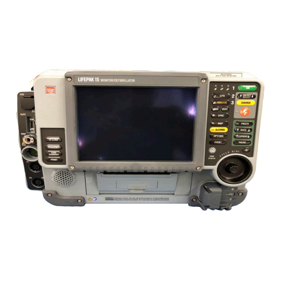
- Page 5 3339111 Rev: Title: LP15 V2 System Board Reprogramming Process 5 of 31 Shock Work Verify Tool Caution Orient Clean Scan Verify Hazard 1. Initial Power Check Install a fully charged battery onto the LIFEPAK 15 monitor/defibrillator. Press the ON key. If the screen flashes white and then becomes blank, the unit is bricked.
- Page 6 3339111 Rev: Title: LP15 V2 System Board Reprogramming Process 6 of 31 Shock Work Verify Tool Caution Orient Clean Scan Verify Hazard 2. Disassembling the Case (Continued) Remove Screws Lay the defibrillator face-down on a protective surface (7 places) to prevent damage, and then remove the 14 case screws (REF 21300-000777).
- Page 7 3339111 Rev: Title: LP15 V2 System Board Reprogramming Process 7 of 31 Shock Work Verify Tool Caution Orient Clean Scan Verify Hazard 2. Disassembling the Case (Continued) Disconnect the P2 system/interface flex cable connector (REF 21330-001226) form the system PCB in the rear case.
- Page 8 3339111 Rev: Title: LP15 V2 System Board Reprogramming Process 8 of 31 Shock Work Verify Tool Caution Orient Clean Scan Verify Hazard 2. Disassembling the Case (Continued) DANGER SHOCK HAZARD: Lethal voltages may be present even without operator action. Always discharge the energy storage capacitor prior to servicing.
- Page 9 3339111 Rev: Title: LP15 V2 System Board Reprogramming Process 9 of 31 Shock Work Verify Tool Caution Orient Clean Scan Verify Hazard 3. Removing the System (A01)/Therapy (A04) PCB Assembly Disconnect PWR/ SYS Cable Disconnect the connectors on the system PCB as (J1) follows: J1- Press the connector locking tabs and disconnect...
- Page 10 3339111 Rev: Title: LP15 V2 System Board Reprogramming Process 10 of 31 Shock Work Verify Tool Caution Orient Clean Scan Verify Hazard 3. Removing the System (A01)/Therapy (A04) PCB Assembly (Continued) Remove Remove the seven screws (REF 21300-001038) and screws one screw with washer (REF 21300-007297) that (7 places) secure the system PCB to the rear case.
- Page 11 3339111 Rev: Title: LP15 V2 System Board Reprogramming Process 11 of 31 Shock Work Verify Tool Caution Orient Clean Scan Verify Hazard 3. Removing the System (A01)/Therapy (A04) PCB Assembly (Continued) Disconnect Disconnect J19 Capacitor J18 Transfer Continue lifting the assembly. Disconnect the (A15) Relay (A13) following connectors on the therapy PCB in the...
- Page 12 3339111 Rev: Title: LP15 V2 System Board Reprogramming Process 12 of 31 Shock Work Verify Tool Caution Orient Clean Scan Verify Hazard 4. Separating the System PCB (A01) Disconnect MTE Flex Cable from J53 of Therapy PCBA. Remove from assembly. Place the system/therapy PCB assembly with the system PCB (REF 21330-001448) face up on your work surface.
- Page 13 3339111 Rev: Title: LP15 V2 System Board Reprogramming Process 13 of 31 Shock Work Verify Tool Caution Orient Clean Scan Verify Hazard 4. Separating the System PCB (A01) (Continued) Remove Spacer And insert hex nut Remove the mounting screw (REF 21300-001030) (Scrap) from the insert hex nut (REF 21300-001478).
- Page 14 3339111 Rev: Title: LP15 V2 System Board Reprogramming Process 14 of 31 Shock Work Verify Tool Caution Orient Clean Scan Verify Hazard 5. Remove the System PCB SBC Shield Remove the six screws securing the SBC shield on the system PCB. Remove the top and bottom SBC shield.
- Page 15 3339111 Rev: Title: LP15 V2 System Board Reprogramming Process 15 of 31 Shock Work Verify Tool Caution Orient Clean Scan Verify Hazard Connect mini USB 6. Debrick the System Board FPGA to FlashPro4 programming tool Ensure the debrick fixture 3339034 Power SW1 is OFF.
- Page 16 3339111 Rev: Title: LP15 V2 System Board Reprogramming Process 16 of 31 Shock Work Verify Tool Caution Orient Clean Scan Verify Hazard 6. Debrick the System Board (Continued) Lock plastic tabs Use two white plastic tabs to lock the system board in place.
- Page 17 3339111 Rev: Title: LP15 V2 System Board Reprogramming Process 17 of 31 Shock Work Verify Tool Caution Orient Clean Scan Verify Hazard 7. Removal of System Board from Debrick Test Fixture Turn the Fixture power switch to OFF. Green LED will turn off to indicate power OFF.
- Page 18 3339111 Rev: Title: LP15 V2 System Board Reprogramming Process 18 of 31 Shock Work Verify Tool Caution Orient Clean Scan Verify Hazard Disconnect 7. Removal of the System Board from Debrick Test Disconnect 30- 24-line cable Fixture (Continued) pin connector P3 from J3 P5 from J5 Disconnect the 30-pin gold connector header P5 from...
- Page 19 3339111 Rev: Title: LP15 V2 System Board Reprogramming Process 19 of 31 Shock Work Verify Tool Caution Orient Clean Scan Verify Hazard 7. Removal of the System Board from the Debrick Test Fixture (Continued) Lift the system board, 3206834, and remove from the debrick fixture 3339034.
- Page 20 3339111 Rev: Title: LP15 V2 System Board Reprogramming Process 20 of 31 Shock Work Verify Tool Caution Orient Clean Scan Verify Hazard 8. Reinstall the System PCB SBC Shield Install six screws to secure the top and bottom SBC shield on the system PCB; torque to 5.0 in-lb. Note: Inspect seal in SBC shield for damage.
- Page 21 3339111 Rev: Title: LP15 V2 System Board Reprogramming Process 21 of 31 Shock Work Verify Tool Caution Orient Clean Scan Verify Hazard 9. Replacing the System PCB (A01) 30 Pin Header REF 21300-001379 Place the therapy PCB facedown with the (Scrap) system/therapy mounting bracket installed.
- Page 22 3339111 Rev: Title: LP15 V2 System Board Reprogramming Process 22 of 31 Shock Work Verify Tool Caution Orient Clean Scan Verify Hazard 9. Replacing the System PCB (A01) Continued Place the second spacer (REF 21300-001479) through the hole in A01 system PCB. Insert new screw (REF 21300-001030) through the spacer stack and into the plastic insert hex nut (REF 21300- Plastic Hex...
- Page 23 3339111 Rev: Title: LP15 V2 System Board Reprogramming Process 23 of 31 Shock Work Verify Tool Caution Orient Clean Scan Verify Hazard 10. Installing the System (A01)/Therapy (A04) PCB Connect J4 USB Assembly Flex (W14) 10.1 Line up the system/therapy assembly with rear case. Connect J1 Power/System 10.2...
- Page 24 3339111 Rev: Title: LP15 V2 System Board Reprogramming Process 24 of 31 Shock Work Verify Tool Caution Orient Clean Scan Verify Hazard 10. Installing the System (A01)/Therapy (A04) PCB Assembly Continued 10.7 Connect the 5-pin connector from the A13 – transfer relay P21 to J21 of the therapy PCB.
- Page 25 3339111 Rev: Title: LP15 V2 System Board Reprogramming Process 25 of 31 Shock Work Verify Tool Caution Orient Clean Scan Verify Hazard Connect MTE 10. Installing the System (A01)/Therapy (A04) PCB Flex to J106 Assembly Continued 10.9 Connect the W20 – MTE flex cable to the biphasic PCB at J106.
- Page 26 3339111 Rev: Title: LP15 V2 System Board Reprogramming Process 26 of 31 Shock Work Verify Tool Caution Orient Clean Scan Verify Hazard 10. Installing the System (A01)/Therapy (A04) PCB Assembly Continued 10.12 Connect the W07 – ECG cable from the parameter Connect ECG bezel to J6 of the system PCB.
- Page 27 3339111 Rev: Title: LP15 V2 System Board Reprogramming Process 27 of 31 Shock Work Verify Tool Caution Orient Clean Scan Verify Hazard 11. Reassembling the Case 11.1 Position the front case over the rear case. Connect J23 11.2 Connect the P23 therapy ribbon cable connector Therapy Ribbon (W11) (REF 21300-007463) from the front case to Connect J24...
- Page 28 3339111 Rev: Title: LP15 V2 System Board Reprogramming Process 28 of 31 Shock Work Verify Tool Caution Orient Clean Scan Verify Hazard Note: 11. Reassembling the Case Continued Seal should not be 11.6 pinched between Install 14 new screws (REF 21300-000777); torque to 10.0 in-lb using a P2 bit.
- Page 29 3339111 Rev: Title: LP15 V2 System Board Reprogramming Process 29 of 31 Shock Work Verify Tool Caution Orient Clean Scan Verify Hazard 11. Reassembling the Case Continued 11.7 Reinstall the right corner bumper (REF 21300- 007356) with 4 screws (REF 21300-007253); torque to 10.0 in-lb using Torx T-15 bit.
- Page 30 3339111 Rev: Title: LP15 V2 System Board Reprogramming Process 30 of 31 Shock Work Verify Tool Caution Orient Clean Scan Verify Hazard 12. Pre-download in DCT 12.1 Follow requirements as outlined in 7000180, Servicing Process Work Instruction 13. Perform PIP/TCP 13.1 Complete Performance Inspection Procedure (PIP) Perform Pre-Download...
- Page 31 3339111 Rev: Title: LP15 V2 System Board Reprogramming Process 31 of 31 Shock Work Verify Tool Caution Orient Clean Scan Verify Hazard Template: 7000743_B...
Need help?
Do you have a question about the LIFEPAK 15 V2 and is the answer not in the manual?
Questions and answers