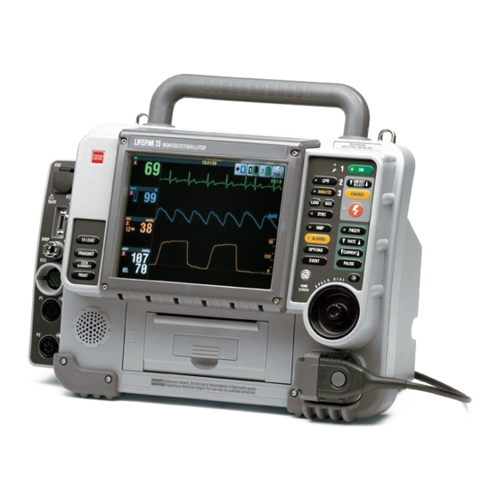
Physio Control LIFEPAK 15 Service Manual
Monitor/defibrillator
Hide thumbs
Also See for LIFEPAK 15:
- Service manual (527 pages) ,
- Operating instructions manual (285 pages) ,
- Upgrade manual (52 pages)

Subscribe to Our Youtube Channel
Related Manuals for Physio Control LIFEPAK 15


Summary of Contents for Physio Control LIFEPAK 15
- Page 1 LIFEPAK ® MONITOR/DEFIBRILLATOR Service Manual © 2018 Physio-Control, Inc. 3316924-003...
-
Page 2: Section Navigator
LIFEPAK 15 Monitor/Defibrillator Section Menu Section Navigator 1 Introduction 5 Troubleshooting 9 Assembly Diagrams and Parts Lists page 11 page 96 page 345 2 Safety 6 Preventive Maintenance page 29 page 147 3 Device Description 7 Battery Maintenance page 48... -
Page 3: Table Of Contents
LIFEPAK 15 Monitor/Defibrillator Table of Contents Service Manual Table of Contents Section Navigator ..................................ii Introduction ....................................11 Trademarks ..................................12 Using Adobe Reader................................. 13 Navigating Through the Manual ............................14 Service Personnel Qualifications............................15 Contacting Physio-Control ..............................16 Responsibility for Information ............................17 Device Tracking ................................ - Page 4 LIFEPAK 15 Monitor/Defibrillator Table of Contents Service Manual Modes of Operation..................................87 Manual Mode .................................. 88 AED Mode ..................................89 Setup Mode..................................90 Service Mode................................... 92 Demo Mode..................................94 Archive Mode .................................. 95 Troubleshooting..................................96 Troubleshooting Chart ..............................97 Using the Service/Status Features ........................... 104 Device Log ................................
- Page 5 LIFEPAK 15 Monitor/Defibrillator Table of Contents Service Manual Service LED .................................. 145 Display Pixels Test ................................. 146 Preventive Maintenance ................................147 Device Self Tests ................................148 Device User Test................................149 Preventive Maintenance and Testing Schedule........................150 Scheduled Replacement Items ............................151 Setting/Resetting the Maintenance Prompt Interval ......................
- Page 6 LIFEPAK 15 Monitor/Defibrillator Table of Contents Service Manual Capacitor Discharging Procedure ............................. 181 Saving and Restoring the Setup Configuration ........................182 Disassembling the Case ..............................183 Reassembling the Case..............................186 Inside Front Case Diagram .............................. 191 Interface PCB (A05) Replacement ........................... 192 Backlight PCB (A08) Replacement ..........................
- Page 7 LIFEPAK 15 Monitor/Defibrillator Table of Contents Service Manual OEM PCB (A06) Replacement............................258 Energy Storage Capacitor (A15) Replacement ........................265 SpO2 PCB (A16) Replacement............................268 NIBP (A21)/CO2 (A23) Module Replacement ........................277 EMI Shield Replacement ..............................287 NIBP Connector Replacement ............................288 Parameter Bezel Replacement............................
- Page 8 Rear Diagrams and Parts List ............................378 OEM Optional Assemblies, Diagrams and Parts Lists ......................389 Label Language Parts ..............................393 LIFEPAK 15 Setup Mode - Instructions..........................422 Connection Diagrams for Assemblies, Control Boards, Cables, and Connectors ..............424 Repair Kits..................................469 Defibrillator Part Number and Serial Number........................
-
Page 9: Introduction
Service Manual Contents Introduction This service manual describes how to maintain, test, troubleshoot, and repair the LIFEPAK 15 monitor/ defibrillator (V4 hardware configuration only). Devices with V4 configuration have the V4 icon on the serial number label. Service instructions for LIFEPAK 15 devices with V1 and V2 hardware configuration are provided in a separate service manual. -
Page 10: Trademarks
Physio-Control, Inc. CODE SUMMARY, CODE-STAT, PARTSLINE, REDI-PAK, Shock Advisory System, SunVue, and DT EXPRESS are trademarks of Physio-Control, Inc. Microsoft and Windows are registered trademarks of Microsoft Corporation in the US and/or other countries. Adobe is a trademark of Adobe Systems Incorporated. Masimo, the Radical logo, Rainbow, and SET are registered trademarks of Masimo Corporation. -
Page 11: Using Adobe Reader
Introduction LIFEPAK 15 Monitor/Defibrillator Using Adobe Reader Service Manual Using Adobe Reader Accessing Adobe Reader Help This service manual opens in Adobe Acrobat Reader. The Adobe Reader can be downloaded for free at the Adobe internet URL http://www.adobe.com/products/reader.html. For additional assistance using the Adobe Reader program, access ADOBE READER HELP in the HELP menu. -
Page 12: Navigating Through The Manual
Introduction LIFEPAK 15 Monitor/Defibrillator Navigating Through the Manual Service Manual Navigating Through the Manual Back Blue text indicates a hyperlink. Click a link to jump to that topic or page. Click in the navigation bar (at the bottom of each page) to return to your previous location. -
Page 13: Service Personnel Qualifications
Service Personnel Qualifications Service Manual Service Personnel Qualifications Service technicians must be properly qualified and thoroughly familiar with the operation of the LIFEPAK 15 monitor/defibrillator. They must meet at least one of the following requirements (or the equivalent): • Associate of Applied Science, with an emphasis in biomedical electronics •... -
Page 14: Contacting Physio-Control
Introduction LIFEPAK 15 Monitor/Defibrillator Contacting Physio-Control Service Manual Contacting Physio-Control Physio-Control, Inc. 11811 Willows Road NE Redmond, WA 98052-2003 USA Telephone: 425.867.4000 Toll Free (USA only): 800.442.1142 Fax: 1.425.867.4861 Internet: www.physio-control.com Physio-Control Operations Netherlands B.V. Galjoenweg 68 6222 NV Maastricht... -
Page 15: Responsibility For Information
Service Manual Responsibility for Information This service manual describes the methods required to maintain, test, and repair the LIFEPAK 15 monitor/defibrillator. This manual does not address the operation of the device. Qualified service personnel (see Service Personnel Qualifications on page 15) must consult this manual and the LIFEPAK 15 Monitor/Defibrillator Operating Instructions to obtain a complete understanding of the use and maintenance of the device. -
Page 16: Device Tracking
Physio-Control, please do one of the following: register the device at http://www.physio-control.com, call the device registration phone line at 1.800.426.4448, or use one of the postage-paid address change cards... -
Page 17: Service Information
To obtain service and maintenance for your device, contact your local Physio-Control service or sales representative. In the USA, call Physio-Control Technical Support at 1.800.442.1142. Outside the USA, contact your local Physio-Control representative. -
Page 18: Recycling Information
• Recycling assistance – The device should be recycled according to national and local regulations. For instructions on disposing of this product or its accessories, see www.physio-control.com/recycling. • Preparation – The device should be clean and contaminant-free prior to being recycled. -
Page 19: Warranty
Using defibrillation electrodes, adapter devices, or other parts and supplies from sources other than Physio-Control is not recommended. Physio-Control has no information regarding the performance or effectiveness of its LIFEPAK defibrillators if they are used in conjunction with defibrillation electrodes or other parts and supplies from other sources. If device failure is attributable to defibrillation electrodes or other parts or supplies not manufactured by Physio-Control, this may void the warranty. -
Page 20: Configuration Information
Configuration Information Service Manual Configuration Information This service manual is relevant for the following device and options: • LIFEPAK 15 monitor/defibrillator Version 4 (V4) device with auxiliary power option • ECG monitoring — standard • Manual mode defibrillation — standard •... -
Page 21: Glossary
Introduction LIFEPAK 15 Monitor/Defibrillator Glossary Service Manual Glossary The following are definitions of terms used throughout this service manual. • Biphasic waveform — Characterized by a positive current phase followed by a reverse current phase of shorter duration and decreased magnitude. The waveform pulse characteristic is biphasic truncated exponential (BTE). - Page 22 • QUIK-COMBO patient simulator — A combination QC therapy cable and ECG lead cardiac rhythm simulator. The simulator is designed for use in training clinical personnel to operate the LIFEPAK 15 monitor/defibrillator. • Pulse Co-oximeter — An optional noninvasive pulse oximeter that measures the saturation of oxygen in arterial blood, carboxyhemoglobin and methemoglobin concentrations, respectively.
-
Page 23: Acronyms
Introduction LIFEPAK 15 Monitor/Defibrillator Acronyms Service Manual Acronyms Table 1.1 lists acronyms and abbreviations used in this manual. Table 1.1— Acronyms and Abbreviations Term Description AAMI Association for the Advancement of Medical Instrumentation Analog-to-digital conversion Automated external defibrillator Ampere hour... - Page 24 Introduction LIFEPAK 15 Monitor/Defibrillator Acronyms Service Manual Table 1.1— Acronyms and Abbreviations (Continued) Cardiopulmonary resuscitation Central processing unit CPSS Continuous patient surveillance system Disposable defibrillation electrodes Digital multimeter Digital signal processor DUART Dual universal asynchronous receiver/transmitter Electrocardiogram Emergency medical service...
- Page 25 Introduction LIFEPAK 15 Monitor/Defibrillator Acronyms Service Manual Table 1.1— Acronyms and Abbreviations (Continued) Light-emitting diode Li-ion Lithium-ion mmHg Millimeters of mercury NIBP Noninvasive blood pressure Normal sinus rhythm Original equipment manufacturer Respiration rate Personal computer Printed circuit board Performance inspection procedure...
- Page 26 Introduction LIFEPAK 15 Monitor/Defibrillator Acronyms Service Manual Table 1.1— Acronyms and Abbreviations (Continued) SpO2 Measurement of oxygen saturation SpMet Measurement of methemoglobin concentration Static-sensitive device Test and calibration procedure Universal serial bus Ventricular fibrillation Vital signs Ventricular tachycardia μA MicroAmpere...
-
Page 27: Safety
Safety This section describes the general safety conventions, terms, and symbols used in this service manual or on the LIFEPAK 15 monitor/defibrillator front and rear panels. This information is intended to alert service personnel to recommended precautions in the care, use, and handling of this medical device. -
Page 28: Terms
Terms Service Manual Terms The following terms are used in this service manual or on the various configurations of the LIFEPAK 15 monitor/defibrillator (device). Familiarize yourself with their definitions and significance. DANGER Immediate hazards that will result in serious personal injury or death. -
Page 29: General Warnings
Service Manual General Warnings The following are general danger, warning, and caution statements. Keep them in mind when working with the LIFEPAK 15 monitor/defibrillator (device). Additional specific warnings and cautions appear throughout this service manual and the LIFEPAK 15 Monitor/Defibrillator Operating Instructions. - Page 30 Safety LIFEPAK 15 Monitor/Defibrillator General Warnings Service Manual WARNINGS SHOCK OR FIRE HAZARDS SHOCK HAZARD The defibrillator delivers up to 360 joules of electrical energy. Unless properly used as described in these operating instructions, this electrical energy may cause serious injury or death. Do not attempt to...
- Page 31 EMS radios on and off. Refer to Appendix D in the Operating Instructions for recommended distances of equipment. Contact Physio-Control Technical Support if assistance is required. POSSIBLE ELECTRICAL INTERFERENCE Using cables, electrodes, or accessories not specified for use with this...
- Page 32 Safety LIFEPAK 15 Monitor/Defibrillator General Warnings Service Manual WARNINGS (CONTINUED) POSSIBLE ELECTRICAL INTERFERENCE This defibrillator may cause electromagnetic interference (EMI) especially during charge and energy transfers. EMI may affect the performance of equipment operating in close proximity. Verify the effects of defibrillator discharge on other equipment prior to using the defibrillator in an emergency situation, if possible.
- Page 33 Safety LIFEPAK 15 Monitor/Defibrillator General Warnings Service Manual WARNINGS (CONTINUED) SAFETY RISK AND POSSIBLE EQUIPMENT DAMAGE POSSIBLE INJURY OR SKIN BURNS Monitors, defibrillators, and their accessories (including electrodes and cables) contain ferromagnetic materials. As with all ferromagnetic equipment, these products must not be used in the presence of the high magnetic field created by a Magnetic Resonance Imaging (MRI) device.
-
Page 34: Symbols
Service Manual Symbols The following list includes symbols that may be used in this service manual or on various configurations of the LIFEPAK 15 monitor/defibrillator and accessories. Some symbols may not be relevant to your device or used in every country. - Page 35 Safety LIFEPAK 15 Monitor/Defibrillator Symbols Service Manual Table 2.1—Symbols (Continued) Symbol Description VF/VT alarm is on, but is silenced or suspended Battery in well, fully charged. For a description of all battery indicators, see Battery Status Indicators (p. 163). Heart rate/pulse rate indicator...
- Page 36 Safety LIFEPAK 15 Monitor/Defibrillator Symbols Service Manual Table 2.1—Symbols (Continued) Symbol Description Greater than Less than Joules Display mode button Home Screen button exhaust Input/output Defibrillation-proof type CF patient connection Defibrillation protected, type BF patient connection Section Menu Section Contents...
- Page 37 Safety LIFEPAK 15 Monitor/Defibrillator Symbols Service Manual Table 2.1—Symbols (Continued) Symbol Description Do not dispose of this product in the unsorted municipal waste stream. Dispose of this product according to local regulations. See www.physio-control.com/recycling for instructions on disposing of this product.
- Page 38 Safety LIFEPAK 15 Monitor/Defibrillator Symbols Service Manual Table 2.1—Symbols (Continued) Symbol Description Reorder number By prescription only Rx Only or Rx Only For USA audiences only !USA Catalog number Manufacturer Indicates that a product complies with applicable ACA standards N13571...
- Page 39 Safety LIFEPAK 15 Monitor/Defibrillator Symbols Service Manual Table 2.1—Symbols (Continued) Symbol Description Battery Static-sensitive device. Static discharge may cause damage. Reports Biphasic defibrillation shock Pace arrow, noninvasive pacing Pace arrow, internal pacing detection QRS sense marker Event marker Section Menu...
- Page 40 Safety LIFEPAK 15 Monitor/Defibrillator Symbols Service Manual Table 2.1—Symbols (Continued) Symbol Description Accessories Mark of conformity to applicable European Directives Recognized component mark for the United States Recognized component mark for Canada and the United States Complies with (USA) Federal Communications Commission regulations Type BF patient connection Lot number (batch code).
- Page 41 Safety LIFEPAK 15 Monitor/Defibrillator Symbols Service Manual Table 2.1—Symbols (Continued) Symbol Description CAUTION - FIRE HAZARD Do not disassemble, heat above 100°C (212°F), or incinerate battery CAUTION - FIRE HAZARD Do not crush, puncture, or disassemble battery Use By date shown: yyyy-mm-dd or yyyy-mm...
- Page 42 Safety LIFEPAK 15 Monitor/Defibrillator Symbols Service Manual Table 2.1—Symbols (Continued) Symbol Description 2 electrodes in 1 package 10 packages in 1 shelf-pak 5 shelf-paks in 1 case Shave patient skin Clean patient skin Treatment Tear here Press electrode firmly onto patient...
- Page 43 Safety LIFEPAK 15 Monitor/Defibrillator Symbols Service Manual Table 2.1—Symbols (Continued) Symbol Description Slowly peel back protective liner on electrode Do not use this pediatric QUIK-COMBO electrode on LIFEPAK 500, ® ® LIFEPAK 1000, LIFEPAK CR Plus, or LIFEPAK EXPRESS defibrillators...
- Page 44 Service Manual Table 2.1—Symbols (Continued) Symbol Description Insert battery in LIFEPAK 15 monitor/defibrillator Rechargeable battery AC-DC power adapter DC-DC power adapter For use with the LIFEPAK 15 monitor/defibrillator Power input Power output DC voltage AC voltage Section Menu Section Contents Back...
- Page 45 Safety LIFEPAK 15 Monitor/Defibrillator Symbols Service Manual Table 2.1—Symbols (Continued) Symbol Description Shipping carton This end up Fragile/breakable Handle with care Protect from water Recommended storage temperature -20° to 60°C (-4° to 140°F) Relative humidity range 10 to 95% Recycle this item...
-
Page 46: Device Description
LIFEPAK 15 Monitor/Defibrillator Device Description Service Manual Contents Device Description This section describes the physical characteristics and functionality of the LIFEPAK 15 monitor/defibrillator (device). Topics include input signals, assembly functions, and device outputs. • Introduction (p. 49) • Physical Description and Features (p. 53) •... -
Page 47: Introduction
• Assemblies (p. 52) About the Device The LIFEPAK 15 monitor/defibrillator provides innovative solutions for emergency response care, all the way from first responders to throughout the hospital. Defibrillation Waveform The device generates a biphasic truncated exponential (BTE) shock pulse for defibrillation. - Page 48 In Manual mode, see Manual Mode (p. 88), the LIFEPAK 15 monitor/defibrillator is a direct current defibrillator that applies a brief, intense pulse of electricity to the heart muscle. Manual mode requires operator interpretation of the ECG rhythm and interaction with the device in order to defibrillate the patient. For more information about Manual mode, see section 5 in the operating instructions.
- Page 49 Device Description LIFEPAK 15 Monitor/Defibrillator Introduction Service Manual ~ Provides operator review of stored events for printout or transmission ~ Captures up to 360 minutes of continuous ECG data ~ Continuous printing of ECG data • Patient signal monitoring —...
- Page 50 Device Description LIFEPAK 15 Monitor/Defibrillator Introduction Service Manual Service features include calibration and diagnostic functions. Assemblies The device consists of a two-piece case assembly that encloses the following: Printed Circuit Boards (when fully configured with options) • • A01 System PCB A07 Contact PCB •...
-
Page 51: Physical Description And Features
Device Description LIFEPAK 15 Monitor/Defibrillator Physical Description and Features Service Manual Physical Description and Features Refer to this topic for a description and list of features for the following: • Front Panel (p. 54) • Rear Panel (p. 61) •... - Page 52 Device Description LIFEPAK 15 Monitor/Defibrillator Physical Description and Features Service Manual Front Panel This section provides information about buttons, indicator LEDs, and connectors on the front panel. Select the area to view on Figure 3.1 on p. 54 Area 2 Area 1 Figure 3.3 (p.
- Page 53 Device Description LIFEPAK 15 Monitor/Defibrillator Physical Description and Features Service Manual Click the appropriate number below to view a description of that feature. See area 2 in Figure 3.3 (p. 59). ENERGY SELECT ANALYZE CHARGE SIZE LEAD SYNC NIBP PACER...
- Page 54 Table 3.1— Front Panel Area 1 Features Number Description VF dose label — Physio-Control recommended energy dose for adult Ventricular Fibrillation (VF) Service LED — Illuminates when service error codes are written into the Service Log (accessed in the Service/Status menu, see Displaying the Service/Status Submenu (p.
- Page 55 Device Description LIFEPAK 15 Monitor/Defibrillator Physical Description and Features Service Manual Table 3.1— Front Panel Area 1 Features (Continued) Number Description OPTIONS button — Accesses optional functions. The options menu selections are: PATIENT, PACING, DATE/TIME, ALARM VOLUME, ARCHIVES, PRINT, and USER TEST.
- Page 56 Device Description LIFEPAK 15 Monitor/Defibrillator Physical Description and Features Service Manual Table 3.1— Front Panel Area 1 Features (Continued) Number Description PAUSED PAUSE button — Temporarily slows pacing rate to 25% of the set rate. While pressed, appears before PPM at the bottom of the screen.
- Page 57 Device Description LIFEPAK 15 Monitor/Defibrillator Physical Description and Features Service Manual Click the appropriate number to view a description of that feature. 12-LEAD SpO2 12-LEAD TRANSMIT NIBP CODE SUMMARY PRINT SpO2 NIBP Figure 3.3—Front panel area 2 Section Menu Section Contents...
- Page 58 Device Description LIFEPAK 15 Monitor/Defibrillator Physical Description and Features Service Manual Table 3.2— Front Panel Area 2 Features Number Description ® CO2 FilterLine set port (optional) — Intake port for the CO2 monitor, which continuously measures the amount of CO2 during each breath and reports the amount present at the end of exhalation (CO2).
- Page 59 Device Description LIFEPAK 15 Monitor/Defibrillator Physical Description and Features Service Manual Rear Panel This section provides information about features on the rear panel. Figure 3.4—Rear features diagram Section Menu Section Contents Back Index...
- Page 60 System connector — Connects device to a gateway or external computer for transfer of patient reports. Also provides real-time ECG output. Auxiliary connector — Connection port for an external power adapter. Battery compartments — Accommodate two removable Lithium-ion batteries that provide power for the LIFEPAK 15 monitor/ defibrillator. Battery contacts — Transfer battery status information.
- Page 61 Device Description LIFEPAK 15 Monitor/Defibrillator Physical Description and Features Service Manual What Is Shipped with a Basic Device A basic device includes the components shown below. QUIK-COMBO electrodes (2) LIFEPAK 15 monitor/ defibrillator QUIK-COMBO therapy cable (no picture) Test Load — for use with...
-
Page 62: Devices, Options, Supplies, And Accessories
Devices, Options, Supplies, and Accessories The following table, provided for reference, summarizes optional configurations, supplies, and accessories that are available. For up-to-date ordering information, contact your Physio-Control representative or order online at store.physio-control.com (U.S. only). Table 3.4— LIFEPAK 15 Configurations... - Page 63 12-lead ECG Accessories: • Main 4-wire cable • 6-wire precordial lead attachment Bluetooth Provides wireless communication to Physio-Control data management products Optional Therapy Delivery Hard paddles Pair (can be used instead of QUIK-COMBO cable and electrodes for defibrillation or sync cardioversion)
- Page 64 Device Description LIFEPAK 15 Monitor/Defibrillator Devices, Options, Supplies, and Accessories Service Manual Table 3.4— LIFEPAK 15 Configurations (Continued) Item Description Electrodes LIFE•PATCH ECG electrodes Sets of 3 or 4 (for monitoring only) • QUIK-COMBO multifunctional ECG Standard — one pair •...
- Page 65 Device Description LIFEPAK 15 Monitor/Defibrillator Devices, Options, Supplies, and Accessories Service Manual Table 3.4— LIFEPAK 15 Configurations (Continued) Item Description Data Management and Communications • Cables Device-to-PC serial interface cable (connects to serial port on a PC or other equipment) •...
- Page 66 Device Description LIFEPAK 15 Monitor/Defibrillator Devices, Options, Supplies, and Accessories Service Manual Table 3.4— LIFEPAK 15 Configurations (Continued) Item Description Supplies • Printer paper 100-mm printer paper — box of 2 rolls • ® SIGNAGEL electrode gel Use with hard paddles...
-
Page 67: System Context Diagrams
Device Description LIFEPAK 15 Monitor/Defibrillator System Context Diagrams Service Manual System Context Diagrams Refer to this section to view diagrams of how the major parts of the system are connected. The diagrams include the following: • Front of Device (p. 70) •... - Page 68 Device Description LIFEPAK 15 Monitor/Defibrillator System Context Diagrams Service Manual Front of Device The following diagrams illustrate how the device connects to external accessories. tubing SpO2 cable NIBP QUIK-COMBO tubing therapy cable Hard paddles Finger (QUIK-COMBO 12-lead 3-lead or sensor...
- Page 69 Device Description LIFEPAK 15 Monitor/Defibrillator System Context Diagrams Service Manual The following diagram illustrates how the device connects to invasive pressure or temperature equipment. Temperature or P1 Accessory cable - Temperature adapter cable P1 and P2 connection - OEM Measurement...
- Page 70 Device Description LIFEPAK 15 Monitor/Defibrillator System Context Diagrams Service Manual Device Communication Bluetooth radio is integrated onto the Interface PCB Figure 3.8—Device system connector Section Menu Section Contents Back Index...
-
Page 71: Functional Descriptions
Service Manual Functional Descriptions The LIFEPAK 15 monitor/defibrillator (device) is a platform medical device capable of combining a variety of therapeutic and monitoring features. In addition to manual defibrillation, semi-automatic defibrillation, and noninvasive pacing, the device offers optional oximetry, invasive pressure, noninvasive blood pressure, CO2, 12-lead ECG, and temperature monitoring. - Page 72 Device Description LIFEPAK 15 Monitor/Defibrillator Functional Descriptions Service Manual • Speaker Assembly (W17) (p. 86) • SpO2 Connector Cable (W22) (p. 86) • CO2 Inlet Connector Cable (W28) (p. 86) • IP Connector Cable (W33) (p. 86) • Temperature Connector Cable (W35) (p. 86)
- Page 73 Device Description LIFEPAK 15 Monitor/Defibrillator Functional Descriptions Service Manual Figure 3.9—System block diagram Section Menu Section Contents Back Index...
- Page 74 Device Description LIFEPAK 15 Monitor/Defibrillator Functional Descriptions Service Manual System PCB (A01) The A01 System PCB integrates and controls all functions of the device. There are two primary components: Single-Board Computer (SBC) The single board computer (SBC) functions as the central processing unit (CPU) for intensive number-processing tasks.
- Page 75 Device Description LIFEPAK 15 Monitor/Defibrillator Functional Descriptions Service Manual detection, and ECG sampling via analog-to-digital conversion (ADC). Results from the ADC process pass across the isolation barrier to the A01 System PCB digital signal processor (DSP) for filtering and signal conditioning before being used by the SBC CPU.
- Page 76 The device can be connected to external equipment for transmitting analog ECG signal output, data transmission, factory test, Physio-Control field service data collection, and device configuration during field upgrade. Except for analog ECG signals, all data communication at the system connector is at RS-232 levels.
- Page 77 Device Description LIFEPAK 15 Monitor/Defibrillator Functional Descriptions Service Manual When the device is OFF, closure of the device power control activates A03 Power PCB circuitry to alert the power processor, which chooses the appropriate source to originate SW_VB (switched battery voltage) power. SW_VB is then routed, in turn, to the A04 Therapy PCB and A01 System PCB for use, as is, and for further processing into system power supply voltages.
- Page 78 Device Description LIFEPAK 15 Monitor/Defibrillator Functional Descriptions Service Manual energy to limit charging to the value selected by the user. Defibrillator energy transfer control To enable the transfer of defibrillation energy, the A04 Therapy PCB integrates control signals from the SHOCK button (or external paddles’...
- Page 79 Device Description LIFEPAK 15 Monitor/Defibrillator Functional Descriptions Service Manual Paddles/QUIK-COMBO ECG preamplifier The ECG paddles/QUIK-COMBO ECG preamplifier perform the functions of patient isolation, electrostatic discharge and defibrillation protection, baseline dc restore, bandwidth filtering, and ECG sampling through analog-to-digital conversion (ADC). Results from the ADC process are fed to the energy delivery processor, paddles sense processor, and paddles control processor.
- Page 80 PCB when it receives an enable signal (LCD_BL_ON) from the A01 System PCB display controller. A separate backlight power supply is mounted on a metal bracket in the front case. Bluetooth Radio Bluetooth radio is integrated onto the Interface PCB. You can transmit current and archived data from the LIFEPAK 15 ® device to the LIFENET System or to post-event review products such as CODE-STAT™...
- Page 81 Device Description LIFEPAK 15 Monitor/Defibrillator Functional Descriptions Service Manual Contact PCB (A07) Interfaces the Li-ion battery edge connector with the device and provides I2C communication to and from the battery. In addition, the device uses a battery pull signal to indicate when the battery is being removed.
- Page 82 Device Description LIFEPAK 15 Monitor/Defibrillator Functional Descriptions Service Manual Energy Storage Capacitor (A15) A metallized film capacitor used for energy storage. The capacitance of the A15 Energy Storage Capacitor is calculated when you perform the TCP – Defibrillator Calibration procedure. The nominal value is 196 μF.
- Page 83 A rear panel connector port used for the exchange of digital information with an external modem, personal computer, factory test systems, or Physio-Control field service test systems. The system connector also supplies a real-time analog ECG signal for use in basic central monitoring or telemetry systems.
- Page 84 Device Description LIFEPAK 15 Monitor/Defibrillator Functional Descriptions Service Manual Speaker Assembly (W17) Used to annunciate device warnings, alarms, tones and, in AED mode, voice prompts. Drive for the W17 Speaker Assembly originates in the A01 System PCB combined audio output block. Final amplification occurs in the A05 Interface PCB audio amplifier.
-
Page 85: Modes Of Operation
Modes of Operation Service Manual Contents Modes of Operation When the LIFEPAK 15 monitor/defibrillator is turned on, it is always in one of six modes of operation. See the following topics to learn more about a particular mode. • Manual Mode (p. -
Page 86: Manual Mode
Modes of Operation LIFEPAK 15 Monitor/Defibrillator Manual Mode Service Manual Manual Mode Entering Manual Mode To enter Manual mode, turn on the device. The factory default settings allow direct access to Manual mode. This access can be modified to require confirmation or a passcode, or can be restricted entirely. -
Page 87: Aed Mode
Modes of Operation LIFEPAK 15 Monitor/Defibrillator AED Mode Service Manual AED Mode About AED Mode and Entering AED Mode Factory default settings allow the device to operate in Manual mode. If you want the device to operate in AED (automated external defibrillator) mode when it is turned on, you must change several setup options in different menus. -
Page 88: Setup Mode
® NOTE: The LIFEPAK Defibrillator Software Solutions Configuration Setup Tool is a Windows -based application designed to assist you in managing the setup options in your LIFEPAK 15 monitor/defibrillator. You can download the tool from http://www.physio-control.com/config.aspx. Section Menu Section Contents... - Page 89 Rotate the SPEED DIAL to select a setup option, and then press the SPEED DIAL to display the option submenu. Setup For more detailed information about Setup mode options, see LIFEPAK 15 Monitor/Defibrillator Setup Options (Example, 26500-003308. See General... Alarms...
-
Page 90: Service Mode
Modes of Operation LIFEPAK 15 Monitor/Defibrillator Service Mode Service Manual Service Mode About Service Mode Service mode functions allow qualified service personnel to: • Perform device calibration routines: ~ Defibrillation calibration ~ Printer calibration ~ CO2 calibration ~ NIBP calibration ~ Temperature calibration •... - Page 91 Modes of Operation LIFEPAK 15 Monitor/Defibrillator Service Mode Service Manual Entering Service Mode To enter the Service mode: Enter the Setup Mode (see Setup Mode (p. 90)) Rotate the SPEED DIAL to select SERVICE in the Setup menu, and then press the SPEED DIAL. The Service mode passcode prompt appears.
-
Page 92: Demo Mode
Modes of Operation LIFEPAK 15 Monitor/Defibrillator Demo Mode Service Manual Demo Mode About Demo Mode Demo mode allows you to practice or demonstrate the monitoring functions of the LIFEPAK 15 monitor/defibrillator, including: • ECG lead selection • SpO2 • SpCO •... -
Page 93: Archive Mode
Modes of Operation LIFEPAK 15 Monitor/Defibrillator Archive Mode Service Manual Archive Mode About Archive Mode and Entering Archive Mode Patient information is stored in Archive mode. When you enter Archive mode, patient monitoring ends and the current Patient Record is saved and closed. -
Page 94: Troubleshooting
LIFEPAK 15 Monitor/Defibrillator Troubleshooting Service Manual Contents Troubleshooting This section describes error code usage, interpretation, and corrective action. It includes a separate troubleshooting chart keyed to the Performance Inspection Procedures (PIP) and individual troubleshooting tests that require operator interpretation. Choose from the following topics: •... -
Page 95: Troubleshooting Chart
Troubleshooting LIFEPAK 15 Monitor/Defibrillator Troubleshooting Chart Service Manual Troubleshooting Chart NOTE: Corrective actions are listed in sequential order according to what is most likely to correct the observed symptom. Table 5.1— Corrective Actions Area Observed Symptom Suggested Corrective Action Physical Inspection Loose or broken hardware Locate and tighten or replace loose items. - Page 96 Troubleshooting LIFEPAK 15 Monitor/Defibrillator Troubleshooting Chart Service Manual Table 5.1— Corrective Actions (Continued) Area Observed Symptom Suggested Corrective Action LCD Display Improper LCD response, wrong colors, Perform Display Pixels Test (p. 146). strips across display Possible W18 LCD Flex Cable Assembly failure.
- Page 97 Troubleshooting LIFEPAK 15 Monitor/Defibrillator Troubleshooting Chart Service Manual Table 5.1— Corrective Actions (Continued) Area Observed Symptom Suggested Corrective Action Printer Test Missing dots in printed “X” Verify use of proper printer paper. Clean the printhead. Check A12 Printer Assembly; replace if necessary.
- Page 98 Troubleshooting LIFEPAK 15 Monitor/Defibrillator Troubleshooting Chart Service Manual Table 5.1— Corrective Actions (Continued) Area Observed Symptom Suggested Corrective Action Power Source Management Verify instructions and retry test. Test If available, verify Aux Power adapter LED is ON and input cable is connected to device.
- Page 99 Troubleshooting LIFEPAK 15 Monitor/Defibrillator Troubleshooting Chart Service Manual Table 5.1— Corrective Actions (Continued) Area Observed Symptom Suggested Corrective Action QUIK-COMBO or Hard No Sync mark Verify test setup and retry test. Paddles Synchronous Adjust ECG size. Cardioversion Test Possible A01 System PCB failure.
- Page 100 Troubleshooting LIFEPAK 15 Monitor/Defibrillator Troubleshooting Chart Service Manual Table 5.1— Corrective Actions (Continued) Area Observed Symptom Suggested Corrective Action Paddles Lead ECG Tests ECG gain out of tolerance Verify test setup and retry test. Check therapy cable; replace if necessary.
- Page 101 Troubleshooting LIFEPAK 15 Monitor/Defibrillator Troubleshooting Chart Service Manual Table 5.1— Corrective Actions (Continued) Area Observed Symptom Suggested Corrective Action Temperature Feature TEMP: ACCURACY OUTSIDE LIMITS Temperature calibration required; verify test setup and test equipment message is displayed, and the accuracy requirements.
-
Page 102: Using The Service/Status Features
Troubleshooting LIFEPAK 15 Monitor/Defibrillator Using the Service/Status Features Service Manual Using the Service/Status Features Introduction The device includes a series of service/status screens and menus that detail device data such as stored manufacturing data, recorded errors, and counters for shock and pacing operation. - Page 103 Troubleshooting LIFEPAK 15 Monitor/Defibrillator Using the Service/Status Features Service Manual Rotate the SPEED DIAL to select STATUS, and then press the SPEED DIAL to display the Service/Status submenu. Section Menu Section Contents Back Index...
-
Page 104: Device Log
Troubleshooting LIFEPAK 15 Monitor/Defibrillator Device Log Service Manual Device Log Introduction The Device Log displays accumulative device operations, such as the shock count. Displaying the Device Log To display the Device Log: Display the Service/Status submenu (Displaying the Service/ Status Submenu (p. - Page 105 Troubleshooting LIFEPAK 15 Monitor/Defibrillator Device Log Service Manual Device Log Entries The Device Log includes the data listed in Table 5.2. Table 5.2—Device Log Entries Data Description Fault Messages Records YES or NO to indicate whether there are any error codes stored in the Service Log (see Processing Service Log Codes (p.
-
Page 106: Device Data
Troubleshooting LIFEPAK 15 Monitor/Defibrillator Device Data Service Manual Device Data Introduction Device Data displays essential device characteristics, such as the serial number and part numbers. Displaying the Device Data To display Device Data: Display the Service/Status submenu (Displaying the Service/Status Submenu (p. - Page 107 Troubleshooting LIFEPAK 15 Monitor/Defibrillator Device Data Service Manual Device Data Entries The device data includes item listed in Table 5.3. Table 5.3—Device Data Entry Data Description Serial Number Device serial number. If the serial number is blank, the device has lost important configuration data.
- Page 108 Troubleshooting LIFEPAK 15 Monitor/Defibrillator Device Data Service Manual Table 5.3—Device Data Entry (Continued) Data Description Bluetooth Version Bluetooth software version number and date stamp Paddles Control SW P/N Therapy assembly software part number and version for the paddles control processor.
-
Page 109: Service Log
Troubleshooting LIFEPAK 15 Monitor/Defibrillator Service Log Service Manual Service Log Introduction The device operating software is designed to detect and report any improper operation or device malfunction by using a system of service codes. When an internal program or process fails to execute properly, a specific four-digit hexadecimal service code is written into the device Service Log (for example, 500e), and the front panel Service LED (p. - Page 110 Troubleshooting LIFEPAK 15 Monitor/Defibrillator Service Log Service Manual Displaying the Service Log To display the Service Log: Display the Service/Status submenu (Displaying the Service/ Status Submenu (p. 104)). Select SERVICE LOG. The Service/Status/Service Log overlay displays service codes by date, time, service code, and extension.
-
Page 111: Processing Service Log Codes
Click the link(s) in the Corrective Action column to view the corresponding corrective action. Service the device based on these inputs, and then repeat the Performance Inspection Procedures (PIP). For persistent Service Log codes, contact your local Physio-Control service or sales representative. Section Menu... -
Page 112: Counters
Troubleshooting LIFEPAK 15 Monitor/Defibrillator Counters Service Manual Counters Introduction The device counters display the number of shocks delivered in both subtotal and running-total counts. Displaying the Counters To display the counters: Display the Service/Status submenu (Displaying the Service/Status Submenu (p. - Page 113 Troubleshooting LIFEPAK 15 Monitor/Defibrillator Counters Service Manual Understanding the Counters The Service/Status/Counters overlay displays the counters shown in Table 5.4. Table 5.4—Counters Data Description Total Shocks Running total of all the shocks ever delivered by the device. This counter cannot be reset.
-
Page 114: Clear Memory
Troubleshooting LIFEPAK 15 Monitor/Defibrillator Clear Memory Service Manual Clear Memory Introduction The Clear Memory feature is used to clear the FLASH data management memory on the A01 System PCB. Specifically, you clear: • ECG Data – All stored ECG data (up to 360 minutes of First-In-First-Out continuous ECG waveforms) is permanently deleted. -
Page 115: Service Log Code Categories
Troubleshooting LIFEPAK 15 Monitor/Defibrillator Service Log Code Categories Service Manual Service Log Code Categories Service log codes are organized into the categories shown in Table 5.5, in four-digit hexadecimal format. Table 5.5—Service Code Categories Initial Digit Category Detail Table Associated PCBs and Assemblies 0xxx Utility Service Codes (p. -
Page 116: Utility Service Codes
Troubleshooting LIFEPAK 15 Monitor/Defibrillator Utility Service Codes Service Manual Utility Service Codes Table 5.6—Initial Digit 0, Utility Service Codes (UT) Corrective Code Service Code Description Action Code 0002 UT_ERROR_FLASH_VPP (Error during flash block erase. Valid for all flash sizes.) 0003 UT_ERROR_FLASH_ERASE (Flash memory block erase failure. -
Page 117: User Interface Service Codes
Troubleshooting LIFEPAK 15 Monitor/Defibrillator User Interface Service Codes Service Manual User Interface Service Codes Initial Digit 1, User Interface Codes (UI) Table 5.7— Service Corrective Code Service Code Description Action Code 1005 UI_ERROR_DISPLAY_SELF_TEST (Self-test failed. Upper 16 bits of status code contain the expected CRC; lower 16 bits contain the actual CRC.) - Page 118 Troubleshooting LIFEPAK 15 Monitor/Defibrillator User Interface Service Codes Service Manual Initial Digit 1, User Interface Codes (UI) Table 5.7— Service (Continued) Corrective Code Service Code Description Action Code 1038 UI_ERROR_CPR_KEY_SEEN (This unit is not configured to support AED mode, but the software saw a key closure of this key.)
-
Page 119: Data Management Service Codes
Troubleshooting LIFEPAK 15 Monitor/Defibrillator Data Management Service Codes Service Manual Data Management Service Codes Table 5.8—Initial Digit 3, Data Management Service Codes (DM) Corrective Code Service Code Description Action Code 3005 DM_ERROR_DATABASE_ERASE_ADJUST (Not able to write new lines for new oldest record; disables flash.) -
Page 120: System Monitor Service Codes
Troubleshooting LIFEPAK 15 Monitor/Defibrillator System Monitor Service Codes Service Manual System Monitor Service Codes Table 5.9—Initial Digit 4, System Monitor Service Codes (SM) Corrective Code Service Code Description Action Code 4009 SM_ERROR_RAM_FAILURE (RAM failure during self-test. 16-bit ram test failure; param = address of failure.) -
Page 121: Processor Control Service Codes
Troubleshooting LIFEPAK 15 Monitor/Defibrillator Processor Control Service Codes Service Manual Processor Control Service Codes Table 5.10—Initial Digit 5, Processor Control Service Codes (PC) Corrective Code Service Code Description Action Code 5002 PC_ERROR_WATCHDOG_SHORT_FAILURE (Main watchdog short test failure. Watchdog failure; param: 0=None, 1=short, 2=long, 3=power.) - Page 122 Troubleshooting LIFEPAK 15 Monitor/Defibrillator Processor Control Service Codes Service Manual Table 5.10—Initial Digit 5, Processor Control Service Codes (PC) Corrective Code Service Code Description Action Code 5019 PC_ERROR_RTC_BAD (RTC is not running.) 2, 1 501a PC_ERROR_RTC_DRIFT (Processor and RTC time out of sync; param = drift.) 5032 PC_ERROR_RTC_NO_BATTERY (No Coin cell battery for the RTC.)
-
Page 123: Ecg Service Codes
Troubleshooting LIFEPAK 15 Monitor/Defibrillator ECG Service Codes Service Manual ECG Service Codes Table 5.11—Initial Digit 6, ECG Service Codes (ECG): Corrective Code Service Code Description Action Code 600c ECG_ERROR_DSP_VOLTAGE (DSP preamp supply voltage out of range.) 600d ECG_ERROR_PREAMP_CALIBRATION (NVRAM calibration constants out of range. HW unit reported calibration error.) 600e ECG_ERROR_NVRAM_FAULT (NVRAM redundant value mismatch detected. -
Page 124: Patient Parameter Service Codes
Troubleshooting LIFEPAK 15 Monitor/Defibrillator Patient Parameter Service Codes Service Manual Patient Parameter Service Codes Table 5.12—Initial Digit 9, Patient Parameter Service Codes (PP) Corrective Code Service Code Description Action Code 900e PPSP_ERROR_CONFIG (SpO2 module detected but not in manufacturing configuration; param: 1 = found Masimo but should not, 2 = unit not found.) -
Page 125: Therapy Service Codes
Troubleshooting LIFEPAK 15 Monitor/Defibrillator Therapy Service Codes Service Manual Therapy Service Codes Table 5.13—Initial Character a, Therapy Service Codes (TH) Corrective Code Service Code Description Action Code a002 TH_ERROR_DEFIB_LINK_DOWN (Lost contact with defib processor. Serial communications link between the main and defib processor is not functioning.This unit can no longer administer defib therapy. - Page 126 Troubleshooting LIFEPAK 15 Monitor/Defibrillator Therapy Service Codes Service Manual Table 5.13—Initial Character a, Therapy Service Codes (TH) Corrective Code Service Code Description Action Code a017 TH_ERROR_DEFIB (Defib. error report) a018 TH_ERROR_PACER (Pacer error report) a01a TH_ERROR_PACER_FAULT (Pacing fault condition occurred [rate(0), current(1), pulse width(2)], limit exceeded; param = pacer-fault 6, 1 type.)
- Page 127 Troubleshooting LIFEPAK 15 Monitor/Defibrillator Therapy Service Codes Service Manual Table 5.13—Initial Character a, Therapy Service Codes (TH) Corrective Code Service Code Description Action Code a02d TH_ERROR_WRONG_DEFIB_TYPE (Wrong Defib. type for software.) 28, 11 a02e TH_ERROR_ADC_READ (ADC read failure when getting cap charge.)
- Page 128 Troubleshooting LIFEPAK 15 Monitor/Defibrillator Therapy Service Codes Service Manual Table 5.13—Initial Character a, Therapy Service Codes (TH) Corrective Code Service Code Description Action Code a104 DE_ERROR_XFER_KEY (Defib HW error.) 28, 10 a106 DE_ERROR_ENERGY_OUT_OF_BOUND (VCAP-1 over/under charge.) a107 DE_ERROR_HP_ENG_SELECT (Cannot determine the rotary setting.) a109 DE_ERROR_CAL_CRC (Calibration Table CRC error.)
- Page 129 Troubleshooting LIFEPAK 15 Monitor/Defibrillator Therapy Service Codes Service Manual Table 5.13—Initial Character a, Therapy Service Codes (TH) Corrective Code Service Code Description Action Code a118 DE_ERROR_TEST_RAM (Defib HW error.) a119 DE_ERROR_TEST_ROM (Defib HW error.) a11a DE_ERROR_TEST_CPU (Defib HW error.) a11d DE_ERROR_XFER_TIMEOUT (Defib HW error.)
- Page 130 Troubleshooting LIFEPAK 15 Monitor/Defibrillator Therapy Service Codes Service Manual Table 5.13—Initial Character a, Therapy Service Codes (TH) Corrective Code Service Code Description Action Code a12d DE_ERROR_CHG_ENABLE_FAIL (Charge enable feedback indicates not charging.) a12e DE_ERROR_BTE_FAULT (Cedar BTE Fault Line State.) a12f DE_ERROR_BTE_FAULT_CLEARED (Cedar BTE Fault Line State.)
- Page 131 Troubleshooting LIFEPAK 15 Monitor/Defibrillator Therapy Service Codes Service Manual Table 5.13—Initial Character a, Therapy Service Codes (TH) Corrective Code Service Code Description Action Code a20f PA_ERROR_A2D_INT (Internal A/D conversion timeout. Set current to zero.) a210 PA_ERROR_A2D_EX (External A/D conversion timeout. Current set to zero.) a211 PA_ERROR_SPI (SPI transfer timeout.
- Page 132 Troubleshooting LIFEPAK 15 Monitor/Defibrillator Therapy Service Codes Service Manual Table 5.13—Initial Character a, Therapy Service Codes (TH) Corrective Code Service Code Description Action Code a21e PA_ERROR_CAL_Z_0 (Impedance 0 calibration failed.) a21f PA_ERROR_PACE_I (Current present when not pacing.) a220 PA_ERROR_NO_HVIS_SENSE (No HV present when pacing.) a221 PA_ERROR_EXT_A2D_TEST (External A/D test register reset failed.)
- Page 133 Troubleshooting LIFEPAK 15 Monitor/Defibrillator Therapy Service Codes Service Manual Table 5.13—Initial Character a, Therapy Service Codes (TH) Corrective Code Service Code Description Action Code a309 TH_PC_ERROR_MSG_SEQUENCING (Paddle Control Comm failure) a30a TH_PC_ERROR_UNEXPECTED_WATCHDOG (Paddle Control Hardware failure) a30b TH_PC_ADC_TIMEOUT (Paddle Control Hardware failure)
- Page 134 Troubleshooting LIFEPAK 15 Monitor/Defibrillator Therapy Service Codes Service Manual Table 5.13—Initial Character a, Therapy Service Codes (TH) Corrective Code Service Code Description Action Code a40a TH_PS_ERROR_ADC_TIMEOUT (Paddle Sensing Hardware failure) a40b TH_PS_ERROR_UNEXPECTED_WATCHDOG (Paddle Sensing Hardware failure) a40c TH_PS_ERROR_RESERVED_1 (Paddle Sensing Hardware failure)
- Page 135 Troubleshooting LIFEPAK 15 Monitor/Defibrillator Therapy Service Codes Service Manual Table 5.13—Initial Character a, Therapy Service Codes (TH) Corrective Code Service Code Description Action Code a506 TH_ED_ADC_TIMEOUT (Energy Delivery Hardware failure (ADC read failure)) a507 TH_ED_ERROR_OSCILLATOR (Energy Delivery Hardware failure (ED oscillator fault, ED switches to the internal DCO clock))
- Page 136 Troubleshooting LIFEPAK 15 Monitor/Defibrillator Therapy Service Codes Service Manual Table 5.13—Initial Character a, Therapy Service Codes (TH) Corrective Code Service Code Description Action Code a51c TH_ED_ERROR_VOLTAGE_ON_CAP (Energy Delivery Hardware failure (Voltage on the CAP when not expected)) a51e TH_ED_ERROR_RELAY_TEST (Energy Delivery/System Control Hardware failure)
-
Page 137: Printer Service Codes
Troubleshooting LIFEPAK 15 Monitor/Defibrillator Printer Service Codes Service Manual Printer Service Codes Table 5.14—Initial Character b, Printer Service Codes (PR) Corrective Code Service Code Description Action Code b001 PR_ERROR_TEMP_TOO_LOW (Printhead ADC reading too low; param = ADC value. May be associated with UT_ERROR_DAC_FAILURE and 13, 28 UT_ERROR_ADC_READ.) -
Page 138: Power Management Service Codes
Troubleshooting LIFEPAK 15 Monitor/Defibrillator Power Management Service Codes Service Manual Power Management Service Codes Table 5.15—Initial Character c, Power Management Service Codes (PM) Corrective Code Service Code Description Action Code c008 PM_ERROR_LOST_COMMS (Lost communications with power PCB.) 7, 1 c009 PM_ERROR_CLOCK_FAILURE (Power PCB is running on its internal oscillator block because it detected an external clock failure.) -
Page 139: Corrective Action Codes
Troubleshooting LIFEPAK 15 Monitor/Defibrillator Corrective Action Codes Service Manual Corrective Action Codes Corrective action codes are referenced in the service code tables under Service Log Code Categories (p. 117). If more than one action is listed under Description, perform them in the order indicated. - Page 140 Processing Service Log Codes section. b. Verify the appropriate connecting cables and wire harnesses are functional. c. Possible A03 Power PCB failure. Device manufacturing configuration bit incorrectly set: (Physio-Control service required). a. Review Processing Service Log Codes section. b. Possible nonvolatile RAM failure on A01 System PCB.
- Page 141 Troubleshooting LIFEPAK 15 Monitor/Defibrillator Corrective Action Codes Service Manual Table 5.16—Corrective Action Codes (Continued) Corrective Description Action Code Configuration or keypad service code: a. Check device configuration settings against installed hardware. b. Review Processing Service Log Codes section. c. Possible A09 Printer Control Keypad or A10 Main Keypad failure.
- Page 142 Troubleshooting LIFEPAK 15 Monitor/Defibrillator Corrective Action Codes Service Manual Table 5.16—Corrective Action Codes (Continued) Corrective Description Action Code The current device software version is recommended, contact Physio-Control Field Service (see Service Information (p. 19)). Clear Data Management memory. Section Menu...
-
Page 143: Service Led
Troubleshooting LIFEPAK 15 Monitor/Defibrillator Service LED Service Manual Service LED What the Service LED Does The Service LED illuminates when a service code is written to the Service Log. Always examine such instances using the instructions in Processing Service Log Codes (p. -
Page 144: Display Pixels Test
Troubleshooting LIFEPAK 15 Monitor/Defibrillator Display Pixels Test Service Manual Display Pixels Test To troubleshoot LCD display viewing issues: Enter the Service mode (see Entering Service Mode (p. 93)) and select TESTS. Select PIXELS in the Service/Tests submenu. The LCD display changes to a uniformly lit screen of medium contrast. -
Page 145: Preventive Maintenance
LIFEPAK 15 Monitor/Defibrillator Preventive Maintenance Service Manual Contents Preventive Maintenance Periodic maintenance, inspection, and testing of the device help prevent and detect possible electrical and mechanical problems. For information about battery charging, conditioning, and battery-related topics, see Battery Maintenance (p. -
Page 146: Device Self Tests
Service Manual Device Self Tests Device Self Test When you turn on the LIFEPAK 15 monitor/defibrillator, a series of self-tests occur. If service codes are detected, the Service LED (p. 145) illuminates. Self-testing does not occur only when the device is turned ON; rather, it is continuous, repeating over and over again while the device is on. -
Page 147: Device User Test
Preventive Maintenance LIFEPAK 15 Monitor/Defibrillator Device User Test Service Manual Device User Test Device User test When you use the SPEED DIAL to navigate to Options/User Test, the device waits until the next self-test cycle is complete. The user test performs the following tasks: •... -
Page 148: Preventive Maintenance And Testing Schedule
Preventive Maintenance LIFEPAK 15 Monitor/Defibrillator Preventive Maintenance and Testing Schedule Service Manual Preventive Maintenance and Testing Schedule shows the schedule for preventive maintenance activities (see the Operator’s Checklist in the operating instructions for additional Table 6.1 items). For items that should be replaced at regular intervals, see Scheduled Replacement Items (p. -
Page 149: Scheduled Replacement Items
Lithium-ion battery pak—Replace to ensure maximum operating time of the device. • Coin battery—Replace to ensure the device will not lose battery power for the real-time clock. NOTE: Contact your Physio-Control Service Representative for assistance when coin battery replacement is required. Table 6.2 shows the schedule for replacement items. -
Page 150: Setting/Resetting The Maintenance Prompt Interval
Preventive Maintenance LIFEPAK 15 Monitor/Defibrillator Setting/Resetting the Maintenance Prompt Interval Service Manual Setting/Resetting the Maintenance Prompt Interval The MAINTENANCE DUE message can be set up to appear at selected intervals (3, 6, or 12 months). When this time interval is reached, the message appears continuously for 10 minutes each time the device is turned on. -
Page 151: Device Useful Life
Device Useful Life During product development, the LIFEPAK 15 monitor/defibrillator and subassemblies are subjected to rigorous life-testing. The routine testing and maintenance program recommended in this service manual will help provide reliable device operation for many years. However, both rapid technological changes and the availability of replacement parts limit the useful life of all modern medical devices. -
Page 152: Support Policy
Support Policy Physio-Control provides full technical support and replacement parts for a period of eight years from the date of shipment from our manufacturing facility. After this eight-year period, Physio-Control provides technical support and replacement parts on an as-available basis. -
Page 153: Cleaning
Preventive Maintenance LIFEPAK 15 Monitor/Defibrillator Cleaning Service Manual Cleaning Tools and Materials The tools and materials needed to perform an external cleaning of the LIFEPAK 15 monitor/defibrillator are listed in Table 6.3. Table 6.3—Cleaning Tools and Materials Product Description Static-discharge-protected work area... - Page 154 Preventive Maintenance LIFEPAK 15 Monitor/Defibrillator Cleaning Service Manual External Cleaning Procedure WARNING SHOCK OR FIRE HAZARD Do not immerse or soak any portion of this device in water or any other fluid. Avoid spilling any fluid on the device or accessories.
- Page 155 Preventive Maintenance LIFEPAK 15 Monitor/Defibrillator Cleaning Service Manual CO2 Input Cleaning Procedure Clean here If CO2 readings do not appear when a new FilterLine is screwed all the way into the CO2 input, the input connector may need to be cleaned.
-
Page 156: Environmental Conditions
Preventive Maintenance LIFEPAK 15 Monitor/Defibrillator Environmental Conditions Service Manual Environmental Conditions Operating Conditions Maintain the following operating temperatures when the device is in use: • 32° to 113°F (0° to 45°C) • -4°F (-20°C) for 1 hour after storage at room temperature •... -
Page 157: A12 Printer Maintenance
Preventive Maintenance LIFEPAK 15 Monitor/Defibrillator A12 Printer Maintenance Service Manual A12 Printer Maintenance Print Roller Cleaning To remove paper debris and other residue from the print roller, soak a cotton swab with alcohol and wipe across the roller surface. Printhead Cleaning Clean the printhead after using approximately 100 rolls of chart paper, or more often if needed. - Page 158 Preventive Maintenance LIFEPAK 15 Monitor/Defibrillator A12 Printer Maintenance Service Manual Paper Sensor Cleaning The paper sensor also requires periodic cleaning to prevent paper debris from blocking the infrared signals that reflect off the paper during normal operation. Clean the sensor whenever the printhead is cleaned. Use a clean cotton swab soaked in clean isopropyl alcohol. Gently wipe the surface of the paper sensor with the tip of the swab.
-
Page 159: Battery Maintenance
Coin Cell Battery (p. 171) For information about the LIFEPAK 15 monitor/defibrillator Li-ion battery chargers, see the Station and Mobile Lithium-ion Battery Chargers Instructions for Use (REF 26500-002904 or 26500-003136), or see the REDI-CHARGE, AC Battery Charger Instructions for Use (REF 26500-003146). -
Page 160: Battery General Characteristics
Battery Charger See "Battery Maintenance" in the operating instructions for additional information about the LIFEPAK 15 contacts monitor/defibrillator Li-ion battery maintenance. NOTE: The LIFEPAK 15 monitor/defibrillator Lithium-ion batteries, battery chargers, and power cords are not interchangeable with batteries, battery chargers, and power cords used in other LIFEPAK defibrillators. -
Page 161: Battery Status Indicators
Battery Maintenance LIFEPAK 15 Monitor/Defibrillator Battery Status Indicators Service Manual Battery Status Indicators Home Screen The Home Screen displays battery indicators that show the following information about the batteries installed in the device: • Presence or absence of battery in battery well •... - Page 162 Battery Fuel Gauge The LIFEPAK 15 Li-ion battery has a pushbutton fuel gauge and the ability to communicate with the Li-ion battery charger. The pushbutton fuel gauge provides a visual indication of battery capacity and battery condition through a series of four green LEDs. Pressing this...
- Page 163 Battery Maintenance LIFEPAK 15 Monitor/Defibrillator Battery Status Indicators Service Manual Table 7.2—Fuel gauge indicator (Continued) # Fuel Gauge LEDs Absolute State of Charge (ASOC) Messaging/Comments 1 yellow 5% < ASOC LOW BATTERY Charge the battery (see Charging the Batteries Using the Station or Mobile Li-ion Battery Charger (p.
-
Page 164: Battery Performance Characteristics
POSSIBLE BATTERY DAMAGE The Li-ion battery charger will not charge batteries if the temperature is below 0°C or above 50°C. Table 7.3 provides the performance characteristics of the LIFEPAK 15 Li-ion batteries (at 20°C). Table 7.3—Li-ion Battery Characteristics Monitoring Pacing... -
Page 165: Charging The Batteries Using The Station Or Mobile Li-Ion Battery Charger
LIFEPAK 15 monitor/defibrillator batteries are charged in the Physio-Control station or Mobile Li-ion Battery Charger. The typical charge time for a fully depleted LIFEPAK 15 Li- ion battery is 4 hours and 15 minutes. To maximize performance and battery life, maintain an ambient temperature for the Li-ion battery charger between 20°... -
Page 166: Discarding/Recycling Batteries
Discarding/Recycling Batteries A properly maintained LIFEPAK 15 Li-ion battery should have a useful life of at least two years, although internal parameters will establish useful battery life. You should discard/recycle a LIFEPAK 15 Li-ion battery under any of the following conditions: •... -
Page 167: Storing Batteries
Always charge a stored battery before placing it in use. A battery is considered to be in storage when it is not in active use. LIFEPAK 15 Li-ion batteries require special handling procedures for storage and then placing in use. •... -
Page 168: Receiving New Batteries
Battery Maintenance LIFEPAK 15 Monitor/Defibrillator Receiving New Batteries Service Manual Receiving New Batteries WARNING POSSIBLE LOSS OF POWER DURING PATIENT CARE New batteries may not be fully charged. Failure to charge a battery before use may cause device power failure without warning. Always charge a new battery before placing it in use. -
Page 169: Coin Cell Battery
Battery Maintenance LIFEPAK 15 Monitor/Defibrillator Coin Cell Battery Service Manual Coin Cell Battery The coin cell battery, REF 21300-001052 (type CR2032), powers the device real-time clock and user-configured settings (custom events and ECG lead sets). The coin cell battery should be replaced every five years. -
Page 170: Replacement Procedures
Service Manual Replacement Procedures The replacement procedures are a set of detailed instructions for disassembly, handling, and reassembly of replaceable LIFEPAK 15 monitor/ defibrillator parts. Perform an interior inspection whenever the LIFEPAK 15 monitor/defibrillator case is opened for service. When disconnecting cables and wire harnesses, label the cables and connections so that they match easily during reassembly, for example, J01, J03, and so forth. -
Page 171: Summary Of Replacement Procedures
Replacement Procedures LIFEPAK 15 Monitor/Defibrillator Summary of Replacement Procedures Service Manual Summary of Replacement Procedures Replacement procedures are referenced and linked in the inside front case diagram (see Inside Front Case Diagram (p. 191)) and inside rear case diagrams (see Inside Rear Case Diagrams (p. - Page 172 Replacement Procedures LIFEPAK 15 Monitor/Defibrillator Summary of Replacement Procedures Service Manual Inside Rear Case Part Replacement Procedures Choose from the following inside rear case replacement procedures (in alphanumerical order): • • Battery Pins / Power PCB Cable (W10) Replacement OEM PCB/SpO2 (W21) Module Cable Replacement (p.
- Page 173 Replacement Procedures LIFEPAK 15 Monitor/Defibrillator Summary of Replacement Procedures Service Manual Additional Part Replacement Procedures Choose from the following procedures (in alphanumerical order) for parts outside the front or rear case. • • Battery Pin Replacement (p. 343) Printer Assembly (A12) Replacement •...
-
Page 174: Warnings And Cautions
Warnings and Cautions Service Manual Warnings and Cautions The following general warnings and cautions apply to all actions you may perform during maintenance of the LIFEPAK 15 monitor/defibrillator. DANGER SHOCK HAZARD Lethal voltages may be present even without operator action. Always discharge the energy storage capacitor prior to servicing. See the service manual “Capacitor Discharging Procedure (p. -
Page 175: Static-Sensitive Device Handling
Replacement Procedures LIFEPAK 15 Monitor/Defibrillator Static-Sensitive Device Handling Service Manual Static-Sensitive Device Handling About SSD Handling Many electronic semiconductor devices (such as MOS ICs, FETs, optical isolators, or film resistors) can be damaged by the discharge of static electricity. Static charge buildup is very common. Static discharges commonly occur when the operator wears synthetic clothes and transfers the charge to any object touched. - Page 176 Replacement Procedures LIFEPAK 15 Monitor/Defibrillator Static-Sensitive Device Handling Service Manual Wear a Wrist Strap Always wear a conductive wrist strap connected to the mat and to ground except when working on energized equipment or when discharging high voltage circuits. The strap must be snug enough to make good contact against bare skin.
-
Page 177: Tools List
Replacement Procedures LIFEPAK 15 Monitor/Defibrillator Tools List Service Manual Tools List The suggested list of tools for the LIFEPAK 15 monitor/defibrillator replacement procedures is as follows: • Static-dissipative mat and wrist strap • Anti-static rack and/or conductive bags • Capacitor discharge tool (information about Capacitor Discharge Tool (p. -
Page 178: Capacitor Discharge Tool
Replacement Procedures LIFEPAK 15 Monitor/Defibrillator Capacitor Discharge Tool Service Manual Capacitor Discharge Tool A capacitor discharge tool is used to discharge the energy storage capacitor (see Capacitor Discharging Neon RTV silicone lamp rubber sealant Procedure (p. 181)). DANGER 5M, 5W 10K, 2W... -
Page 179: Capacitor Discharging Procedure
Replacement Procedures LIFEPAK 15 Monitor/Defibrillator Capacitor Discharging Procedure Service Manual Capacitor Discharging Procedure After disassembling the case as described in Disassembling the Case (p. 183), immediately discharge the energy storage capacitor using the capacitor discharge tool as described in Using the Capacitor Discharge Tool (p. -
Page 180: Saving And Restoring The Setup Configuration
® NOTE: The LIFEPAK Defibrillator Software Solutions Configuration Setup Tool is a Windows -based application designed to assist you in managing the setup options in your LIFEPAK 15 monitor/defibrillator. You can download the tool from http://www.physio-control.com/config.aspx. Printing the Setup Configuration ... -
Page 181: Disassembling The Case
Replacement Procedures LIFEPAK 15 Monitor/Defibrillator Disassembling the Case Service Manual Disassembling the Case Refer to Front Parts Diagrams and Parts List (p. 356) Rear Diagrams and Parts List (p. 378). To disassemble the case halves: 12 steps, (Page 1 of 3) If applicable, remove carrying case. - Page 182 Replacement Procedures LIFEPAK 15 Monitor/Defibrillator Disassembling the Case Service Manual To disassemble the case halves: (Continued) 12 steps, (Page 2 of 3) Lay the defibrillator face-down on a protective surface to prevent damage, and then remove the 14 case screws.
- Page 183 Replacement Procedures LIFEPAK 15 Monitor/Defibrillator Disassembling the Case Service Manual To disassemble the case halves: (Continued) 12 steps, (Page 3 of 3) Disconnect the P2 system/interface flex cable connector (W04) from the system PCB (see Figure 9.21 on p.
-
Page 184: Reassembling The Case
Replacement Procedures LIFEPAK 15 Monitor/Defibrillator Reassembling the Case Service Manual Reassembling the Case To reassemble the case halves: 13 steps, (Page 1 of 5) Position the front case over the rear case. Connect the P23 therapy ribbon cable connector (W11) (REF 21330-001510) from the front case to J23 of therapy (Figure 9.23 on p. - Page 185 Replacement Procedures LIFEPAK 15 Monitor/Defibrillator Reassembling the Case Service Manual To reassemble the case halves: (Continued) 13 steps, (Page 2 of 5) Carefully connect the P2 system/interface flex cable connector (W04) (REF 21330-001226) to the system PCB in the rear case (Figure 9.21 on p.
- Page 186 Replacement Procedures LIFEPAK 15 Monitor/Defibrillator Reassembling the Case Service Manual To reassemble the case halves: (Continued) 13 steps, (Page 3 of 5) Install 14 new screws (REF 21300-000777); torque to 10.0 in-lb using a P2 bit. Screw locations Screw...
- Page 187 Replacement Procedures LIFEPAK 15 Monitor/Defibrillator Reassembling the Case Service Manual To reassemble the case halves: (Continued) 13 steps, (Page 4 of 5) Reinstall the right corner bumper (REF 21300-007356) with 4 screws (REF 21300-007253); torque to 10.0 in-lb using Torx T-15 bit.
- Page 188 Replacement Procedures LIFEPAK 15 Monitor/Defibrillator Reassembling the Case Service Manual To reassemble the case halves: (Continued) 13 steps, (Page 5 of 5) Install the batteries. NOTE: Pay special attention to the SERVICE indicator as you turn on the device in the next step.
-
Page 189: Inside Front Case Diagram
Replacement Procedures LIFEPAK 15 Monitor/Defibrillator Inside Front Case Diagram Service Manual Inside Front Case Diagram Use the following diagram after disassembling the case as described in Disassembling the Case (p. 183). Backlight PCB (A08) Replacement Main Keypad/Interface PCB LCD Display... -
Page 190: Interface Pcb (A05) Replacement
Replacement Procedures LIFEPAK 15 Monitor/Defibrillator Interface PCB (A05) Replacement Service Manual Interface PCB (A05) Replacement Interface PCB Replacement Figures Screws Ground strap screw Screws Figure 8.9—Interface PCB screw locations Section Menu Section Contents Procedures Back Index... - Page 191 Replacement Procedures LIFEPAK 15 Monitor/Defibrillator Interface PCB (A05) Replacement Service Manual W18 - LCD cable (REF 21330-001417) - J36 W13 - Main keypad cable (REF 21330-001323) - J31 W04 - System flex cable W12 - Printer control (REF 21330-001226) - J30...
- Page 192 Replacement Procedures LIFEPAK 15 Monitor/Defibrillator Interface PCB (A05) Replacement Service Manual W06 - Backlight inverter cable (REF 21330-001525 - J37 W16 - printer interface cable (REF 21330-000165) - J35 W15 - speed dial (rotary switch) cable - Figure 8.11—Interface PCB cable connection locations - view 2 of 2...
- Page 193 Replacement Procedures LIFEPAK 15 Monitor/Defibrillator Interface PCB (A05) Replacement Service Manual Removing the Interface PCB (A05) Refer to Interface PCB Replacement Figures (p. 192) Inside Front Case Diagram (p. 191). To remove the interface PCB (REF 21330-001533) from the front case: Disassemble the case as described in Disassembling the Case (p.
- Page 194 Replacement Procedures LIFEPAK 15 Monitor/Defibrillator Interface PCB (A05) Replacement Service Manual Installing the Interface PCB (A05) Refer to Interface PCB Replacement Figures (p. 192) Inside Front Case Diagram (p. 191). To install the interface PCB into the front case:...
-
Page 195: Backlight Pcb (A08) Replacement
Replacement Procedures LIFEPAK 15 Monitor/Defibrillator Backlight PCB (A08) Replacement Service Manual Backlight PCB (A08) Replacement The backlight PCB replacement consists of: • Removing the Backlight PCB (A08) (p. 198) • Installing the Backlight PCB (A08) (p. 199) Refer to Inside Front Case Diagram (p. - Page 196 Replacement Procedures LIFEPAK 15 Monitor/Defibrillator Backlight PCB (A08) Replacement Service Manual Removing the Backlight PCB (A08) To remove the backlight PCB from the front case: Disassemble the case as described in Disassembling the Case (p. 183). Remove the interface PCB as described in...
- Page 197 Replacement Procedures LIFEPAK 15 Monitor/Defibrillator Backlight PCB (A08) Replacement Service Manual Installing the Backlight PCB (A08) To install the backlight PCB into the front case: NOTE: If a new backlight PCB is required, install the Display Driver Repair Kit (REF 40577-000001) (p. 477) along with Display Repair Kit (REF 40577-00044) (p.
-
Page 198: Printer Control Keypad (A09) Replacement
Replacement Procedures LIFEPAK 15 Monitor/Defibrillator Printer Control Keypad (A09) Replacement Service Manual Printer Control Keypad (A09) Replacement Printer control keypad replacement consists of the following: • Removing the Printer Control Keypad (A09) (p. 201) • Installing the Printer Control Keypad (A09) (p. 201) Figure 8.14—Printer control keypad replacement... - Page 199 Replacement Procedures LIFEPAK 15 Monitor/Defibrillator Printer Control Keypad (A09) Replacement Service Manual Removing the Printer Control Keypad (A09) Refer to Figure 8.14 on p. 200. To remove the printer control keypad from outside the front case: Using a very thin, wide, flat-edged tool (example, 1.5” putty knife), gently pry one edge of the printer control keypad until it is released from its adhesive mount.
-
Page 200: Main Keypad (A10) Replacement
Replacement Procedures LIFEPAK 15 Monitor/Defibrillator Main Keypad (A10) Replacement Service Manual Main Keypad (A10) Replacement Main keypad replacement consists of the following: • Removing the Main Keypad (A10) (p. 203) • Installing the Main Keypad (A10) (p. 203) Figure 8.15—Main keypad... - Page 201 Replacement Procedures LIFEPAK 15 Monitor/Defibrillator Main Keypad (A10) Replacement Service Manual Removing the Main Keypad (A10) Refer to Figure 8.15 on p. 202. To remove the main keypad from outside the front case: Using a very thin, wide, flat-edged tool (example, 1.5” putty knife), gently pry one edge of the main keypad until it is released from its adhesive mount.
-
Page 202: Display Shield Replacement
Replacement Procedures LIFEPAK 15 Monitor/Defibrillator Display Shield Replacement Service Manual Display Shield Replacement Inside Front Case Diagram (p. 191) Refer to Figure 9.5 (p. 357). Screw locations Figure 8.16—Display shield screw locations Section Menu Section Contents Procedures Back Index... - Page 203 Replacement Procedures LIFEPAK 15 Monitor/Defibrillator Display Shield Replacement Service Manual Removing the Display Lens Shield Refer to Figure 8.16 on p. 204. To remove the display shield from outside the front case: Remove the four screws from the display shield.
-
Page 204: Lcd Display Assembly (A11) Replacement
Replacement Procedures LIFEPAK 15 Monitor/Defibrillator LCD Display Assembly (A11) Replacement Service Manual LCD Display Assembly (A11) Replacement The LCD display assembly replacement includes: • Removing the LCD Display Assembly (A11) (p. 207) • Installing the LCD Display Assembly (A11) (p. 207) Refer to Inside Front Case Diagram (p. - Page 205 Replacement Procedures LIFEPAK 15 Monitor/Defibrillator LCD Display Assembly (A11) Replacement Service Manual Removing the LCD Display Assembly (A11) To remove the LCD display assembly from the front case (Inside Front Case Diagram (p. 191): Disassemble the case as described in Disassembling the Case (p.
- Page 206 Replacement Procedures LIFEPAK 15 Monitor/Defibrillator LCD Display Assembly (A11) Replacement Service Manual Install the interface PCB as described in Installing the Interface PCB (A05) (p. 196). Reassemble the case as described in Reassembling the Case (p. 186). Section Menu Section Contents...
-
Page 207: Display Lens Replacement
Replacement Procedures LIFEPAK 15 Monitor/Defibrillator Display Lens Replacement Service Manual Display Lens Replacement Inside Front Case Diagram (p. 191) Refer to Figure 9.5 (p. 357). Removing the Display Lens To remove the display lens from outside the front case: NOTE: Removing the front lens requires high direct pressure to remove. - Page 208 Replacement Procedures LIFEPAK 15 Monitor/Defibrillator Display Lens Replacement Service Manual Installing the Display Lens Refer to Figure 8.18 on p. 209. To install the display lens onto the front case: Using a soft, lint-free cloth and isopropyl alcohol, gently remove old adhesive from lens frame on the front case.
-
Page 209: Front Case Replacement
Replacement Procedures LIFEPAK 15 Monitor/Defibrillator Front Case Replacement Service Manual Front Case Replacement Refer to Inside Front Case Diagram (p. 191) Figure 8.19—Front case replacement Section Menu Section Contents Procedures Back Index... - Page 210 Replacement Procedures LIFEPAK 15 Monitor/Defibrillator Front Case Replacement Service Manual Disassembling the Front Case Refer to Figure 8.19 on p. 211. To disassemble the front case: Remove the printer assembly as described in Removing the Printer Assembly (A12) (p.
- Page 211 Replacement Procedures LIFEPAK 15 Monitor/Defibrillator Front Case Replacement Service Manual Assembling the Front Case Refer to Figure 8.19 on p. 211. To install the new front case: 15 steps, (Page 1 of 2) NOTE: Use the Front Case Repair Kit (REF 40577-000010) (p.
- Page 212 12. Reassemble the case as described in Reassembling the Case (p. 186). 13. Clean the front case with isopropyl alcohol, and apply Physio-Control logo (REF 21501-002038) to the location provided in upper left of front case. 14. Install the printer assembly as described in Installing the Printer Assembly (A12) (p.
-
Page 213: System/Interface Pcb Cable (W04) Replacement
Replacement Procedures LIFEPAK 15 Monitor/Defibrillator System/Interface PCB Cable (W04) Replacement Service Manual System/Interface PCB Cable (W04) Replacement Refer to Inside Front Case Diagram (p. 191). to A05 - J30 to A01 - J2 Removing the System/Interface PCB Cable (W04) ... -
Page 214: Backlight/Interface Pcb Cable (W06) Replacement
Replacement Procedures LIFEPAK 15 Monitor/Defibrillator Backlight/Interface PCB Cable (W06) Replacement Service Manual Backlight/Interface PCB Cable (W06) Replacement Refer to Inside Front Case Diagram (p. 191). to A05 - J37 Removing the Backlight/interface PCB (W06) Cable To remove the backlight/interface W06 cable (REF 21330-001525) (see Figure 9.42 on... -
Page 215: Therapy Connector Cable (W11) Replacement
Replacement Procedures LIFEPAK 15 Monitor/Defibrillator Therapy Connector Cable (W11) Replacement Service Manual Therapy Connector Cable (W11) Replacement Refer to Inside Front Case Diagram (p. 191). Removing the Therapy Connector Cable (W11) To remove the therapy connector cable (see Figure 9.47 on p. - Page 216 Replacement Procedures LIFEPAK 15 Monitor/Defibrillator Therapy Connector Cable (W11) Replacement Service Manual To install the therapy Connector cable into the front case: (Continued) 4 steps, (Page 2 of 2) From the outside of the front case, insert the new therapy Connector cable through the therapy mounting seal and front case.
-
Page 217: Printer Control Keypad/Interface Pcb Cable (W12) Replacement
Replacement Procedures LIFEPAK 15 Monitor/Defibrillator Printer Control Keypad/Interface PCB Cable (W12) Service Manual Replacement Printer Control Keypad/Interface PCB Cable (W12) Replacement Refer to Inside Front Case Diagram (p. 191). to A09 - J41 Removing the Printer Control Keypad/Interface PCB Cable (W12) See diagram on Figure 9.28 on p. -
Page 218: Main Keypad/Interface Pcb Cable (W13) Replacement
Replacement Procedures LIFEPAK 15 Monitor/Defibrillator Main Keypad/Interface PCB Cable (W13) Replacement Service Manual Main Keypad/Interface PCB Cable (W13) Replacement Refer to Inside Front Case Diagram (p. 191). Removing the Main Keypad/Interface PCB Cable (W13) to A10 - J39 to A05 - J31 ... -
Page 219: Speed Dial Assembly (W15) Replacement
Replacement Procedures LIFEPAK 15 Monitor/Defibrillator Speed Dial Assembly (W15) Replacement: Service Manual Speed Dial Assembly (W15) Replacement: Cable connection to J33 Removing the Speed Dial Assembly (W15) To remove the speed dial assembly (REF 21300-003713) (see Figure 9.51 on p. - Page 220 Replacement Procedures LIFEPAK 15 Monitor/Defibrillator Speed Dial Assembly (W15) Replacement: Service Manual To remove the speed dial assembly (REF 21300-003713) (see Figure 9.51 on p. 455) from the front case: (Continued) 5 steps, (Page 2 of 2) From the outside of the case, loosen and remove the nut and lock washer (part of the speed dial assembly) from the speed dial assembly shaft.
-
Page 221: Installing The Speed Dial Assembly (W15)
Replacement Procedures LIFEPAK 15 Monitor/Defibrillator Installing the Speed Dial Assembly (W15) Service Manual Installing the Speed Dial Assembly (W15) Rear of switch, orient with cable toward PCB To install the speed dial assembly into the front case (Inside Front Case Diagram (p. -
Page 222: Printer Assembly/Interface Pcb Cable (W16) Replacement
Replacement Procedures LIFEPAK 15 Monitor/Defibrillator Printer Assembly/Interface PCB Cable (W16) Replacement Service Manual Printer Assembly/Interface PCB Cable (W16) Replacement Refer to Inside Front Case Diagram (p. 191). to A05 - J35 Removing the Printer Assembly/Interface PCB Cable (W16) To remove the printer/interface PCB cable (REF 21330-000165) (see Figure 9.52 on p. - Page 223 Replacement Procedures LIFEPAK 15 Monitor/Defibrillator Printer Assembly/Interface PCB Cable (W16) Replacement Service Manual Installing the Printer Assembly/Interface PCB Cable (W16) Refer to Figure 8.29 on p. 224. To install the printer/interface PCB cable (W16) into the front case: NOTE: When installing printer/interface PCB cable (REF 21330-000165) use External Hardware Repair Kit (REF 40577- 000004) (p.
-
Page 224: Speaker Assembly (W17) Replacement
Replacement Procedures LIFEPAK 15 Monitor/Defibrillator Speaker Assembly (W17) Replacement Service Manual Speaker Assembly (W17) Replacement Refer to Inside Front Case Diagram (p. 191). Cable connection to J34 Screw location Retaining spring Figure 8.30—Speaker assembly replacement cable connection and screw location... - Page 225 Replacement Procedures LIFEPAK 15 Monitor/Defibrillator Speaker Assembly (W17) Replacement Service Manual Removing the Speaker Assembly (W17) Refer to Figure 8.30 on p. 226. To remove the Speaker Assembly (REF 21300-001371) (see Figure 9.53 on p. 457) from the front case: Disassemble the case as described in Disassembling the Case (p.
- Page 226 Replacement Procedures LIFEPAK 15 Monitor/Defibrillator Speaker Assembly (W17) Replacement Service Manual Installing the Speaker Assembly (W17) Refer to Figure 8.30 on p. 226. To install the Speaker Assembly into the front case (Inside Front Case Diagram (p. 191)): NOTE: When installing speaker assembly (REF 21300-001371) use External Hardware Repair Kit (REF 40577-000004) (p.
-
Page 227: Lcd Display Assembly/Interface Pcb Cable (W18) Replacement
Replacement Procedures LIFEPAK 15 Monitor/Defibrillator LCD Display Assembly/Interface PCB Cable (W18) Service Manual Replacement LCD Display Assembly/Interface PCB Cable (W18) Replacement Refer to Inside Front Case Diagram (p. 191). Removing the LCD Display Assembly/Interface PCB Cable (W18) To remove the LCD display/interface PCB W18 cable (REF 21330-001417) -
Page 228: Printer Assembly/Chassis Ground Cable (W19) Replacement
Replacement Procedures LIFEPAK 15 Monitor/Defibrillator Printer Assembly/Chassis Ground Cable (W19) Replacement Service Manual Printer Assembly/Chassis Ground Cable (W19) Replacement Refer to Inside Front Case Diagram (p. 191). Chassis ground Removing the Printer Assembly/Chassis Ground Cable (W19) To remove the printer/chassis ground W19 cable 21300-001370) (see Figure 9.55 on p. -
Page 229: Inside Rear Case Diagrams
Replacement Procedures LIFEPAK 15 Monitor/Defibrillator Inside Rear Case Diagrams Service Manual Inside Rear Case Diagrams The inside rear case diagrams include the following: • Rear Case Overview (p. 232) • Rear Case Overview with System (A01)/Therapy (A04) PCBs Removed (p. 233) Numerous repair procedures refer to these diagrams. - Page 230 Replacement Procedures LIFEPAK 15 Monitor/Defibrillator Inside Rear Case Diagrams Service Manual Rear Case Overview Use this diagram after disassembling the case as described in Disassembling the Case (p. 183). Coin Battery Replacement Disassembly screw (typical) Power/System PCB Cable (W01) Replacement...
- Page 231 Replacement Procedures LIFEPAK 15 Monitor/Defibrillator Inside Rear Case Diagrams Service Manual Rear Case Overview with System (A01)/Therapy (A04) PCBs Removed Diagram shows rear case view after removing the A01 system and A04 therapy PCBs as described in System (A01)/Therapy (A04) PCB Assembly Replacement (p.
-
Page 232: System (A01)/Therapy (A04) Pcb Assembly Replacement
Replacement Procedures LIFEPAK 15 Monitor/Defibrillator System (A01)/Therapy (A04) PCB Assembly Replacement Service Manual System (A01)/Therapy (A04) PCB Assembly Replacement The system/therapy PCB assembly is removed as a unit and then separated. Refer to System/Therapy PCB Assembly Diagrams and Parts Lists (p. - Page 233 Replacement Procedures LIFEPAK 15 Monitor/Defibrillator System (A01)/Therapy (A04) PCB Assembly Replacement Service Manual Removing the System (A01)/Therapy (A04) PCB Assembly To remove the system/therapy PCBs as a single unit from the rear case: 9 steps, (Page 1 of 3)
- Page 234 Replacement Procedures LIFEPAK 15 Monitor/Defibrillator System (A01)/Therapy (A04) PCB Assembly Replacement Service Manual To remove the system/therapy PCBs as a single unit from the rear case: (Continued) 9 steps, (Page 2 of 3) Remove the seven screws and two screws with washer that secures the system PCB to the rear case.
- Page 235 Replacement Procedures LIFEPAK 15 Monitor/Defibrillator System (A01)/Therapy (A04) PCB Assembly Replacement Service Manual To remove the system/therapy PCBs as a single unit from the rear case: (Continued) 9 steps, (Page 3 of 3) Carefully lift system/therapy PCB assembly to gain access to the cables below.
-
Page 236: Installing The System (A01)/Therapy (A04) Pcb Assembly
Replacement Procedures LIFEPAK 15 Monitor/Defibrillator Installing the System (A01)/Therapy (A04) PCB Assembly Service Manual Installing the System (A01)/Therapy (A04) PCB Assembly To install the system/therapy PCB: 13 steps, (Page 1 of 4) Line up the system/therapy assembly with rear case. - Page 237 Replacement Procedures LIFEPAK 15 Monitor/Defibrillator Installing the System (A01)/Therapy (A04) PCB Assembly Service Manual To install the system/therapy PCB: (Continued) 13 steps, (Page 2 of 4) Connect P22 of the therapy cap wire harness (W24) to J22 of cap discharge PCB assembly.
- Page 238 Replacement Procedures LIFEPAK 15 Monitor/Defibrillator Installing the System (A01)/Therapy (A04) PCB Assembly Service Manual To install the system/therapy PCB: (Continued) 13 steps, (Page 3 of 4) Line up the system PCB with the inserts in the rear case, and secure with seven new screws (REF 21300-001038;...
- Page 239 Replacement Procedures LIFEPAK 15 Monitor/Defibrillator Installing the System (A01)/Therapy (A04) PCB Assembly Service Manual To install the system/therapy PCB: (Continued) 13 steps, (Page 4 of 4) 10. Connect the W07 - ECG cable from the parameter bezel to J6 of the system PCB.
- Page 240 Replacement Procedures LIFEPAK 15 Monitor/Defibrillator Installing the System (A01)/Therapy (A04) PCB Assembly Service Manual Separating the System PCB (A01) To separate the system PCB (A01) from the therapy PCB (A04): 6 steps, (Page 1 of 2) Disassemble the case as...
- Page 241 Replacement Procedures LIFEPAK 15 Monitor/Defibrillator Installing the System (A01)/Therapy (A04) PCB Assembly Service Manual To separate the system PCB (A01) from the therapy PCB (A04): (Continued) 6 steps, (Page 2 of 2) Place the system/therapy PCB assembly with the system PCB face up on your work surface.
- Page 242 Replacement Procedures LIFEPAK 15 Monitor/Defibrillator Installing the System (A01)/Therapy (A04) PCB Assembly Service Manual Replacing the System PCB (A01) To replace the system PCB (A01): NOTE: When replacing the System PCB, use System PCBA Repair Kit V4 (REF 40577-000031) (p.
- Page 243 Replacement Procedures LIFEPAK 15 Monitor/Defibrillator Installing the System (A01)/Therapy (A04) PCB Assembly Service Manual Separating the Therapy PCB (A04) To remove the therapy PCB (A04): 7 steps, (Page 1 of 2) Disassemble the case as Screw locations (4 places)
- Page 244 Replacement Procedures LIFEPAK 15 Monitor/Defibrillator Installing the System (A01)/Therapy (A04) PCB Assembly Service Manual To remove the therapy PCB (A04): (Continued) 7 steps, (Page 2 of 2) Gently lift the therapy PCB up and away from the system PCB.
- Page 245 Replacement Procedures LIFEPAK 15 Monitor/Defibrillator Installing the System (A01)/Therapy (A04) PCB Assembly Service Manual Replacing the Therapy PCB (A04) To replace the therapy PCB (A04): 7 steps, (Page 1 of 3) NOTE: When replacing the therapy PCB, use Therapy PCBA Repair Kit (REF 40577-000032) (p.
- Page 246 Replacement Procedures LIFEPAK 15 Monitor/Defibrillator Installing the System (A01)/Therapy (A04) PCB Assembly Service Manual To replace the therapy PCB (A04): (Continued) 7 steps, (Page 2 of 3) Align the therapy PCB Screw locations (4 places) (REF 21330-001538) with the system PCB.
- Page 247 Replacement Procedures LIFEPAK 15 Monitor/Defibrillator Installing the System (A01)/Therapy (A04) PCB Assembly Service Manual To replace the therapy PCB (A04): (Continued) 7 steps, (Page 3 of 3) Follow the instructions to install the system/therapy assembly into device as described in Installing the System (A01)/Therapy (A04) PCB Assembly (p.
-
Page 248: Power Pcb (A03) Replacement
Replacement Procedures LIFEPAK 15 Monitor/Defibrillator Power PCB (A03) Replacement Service Manual Power PCB (A03) Replacement Power PCB Replacement consists of the following procedures: • Removing the Power PCB (A03) (p. 251) • Installing the Power PCB (A03) (p. 254) Section Menu... - Page 249 Replacement Procedures LIFEPAK 15 Monitor/Defibrillator Power PCB (A03) Replacement Service Manual Removing the Power PCB (A03) Some parts mentioned in this procedure are optional and may not apply to your device. To remove the power PCB (A03) from the rear case: 10 steps, (Page 1 of 3)
- Page 250 Replacement Procedures LIFEPAK 15 Monitor/Defibrillator Power PCB (A03) Replacement Service Manual To remove the power PCB (A03) from the rear case: (Continued) 10 steps, (Page 2 of 3) Mounting screws Remove the two screws securing the bracket assembly. (2 places) Discard the screws.
- Page 251 Replacement Procedures LIFEPAK 15 Monitor/Defibrillator Power PCB (A03) Replacement Service Manual To remove the power PCB (A03) from the rear case: (Continued) 10 steps, (Page 3 of 3) Remove the W01 power/system PCB cable at J17 for reuse with the new power PCB.
- Page 252 Replacement Procedures LIFEPAK 15 Monitor/Defibrillator Power PCB (A03) Replacement Service Manual Installing the Power PCB (A03) Some parts mentioned in this procedure are optional and may not apply to your device. To install the power PCB (A03) into the rear case: 11 steps, (Page 1 of 4)
- Page 253 Replacement Procedures LIFEPAK 15 Monitor/Defibrillator Power PCB (A03) Replacement Service Manual To install the power PCB (A03) into the rear case: (Continued) 11 steps, (Page 2 of 4) Mount the power PCB in the case and secure the bracket (REF 21330-001257) to the rear case using two new screws (REF 21300-001038);...
- Page 254 Replacement Procedures LIFEPAK 15 Monitor/Defibrillator Power PCB (A03) Replacement Service Manual To install the power PCB (A03) into the rear case: (Continued) 11 steps, (Page 3 of 4) Connect battery pins/power PCB cable (W10) to the PINCH HAZARD: power board at J11.
- Page 255 Replacement Procedures LIFEPAK 15 Monitor/Defibrillator Power PCB (A03) Replacement Service Manual To install the power PCB (A03) into the rear case: (Continued) 11 steps, (Page 4 of 4) Route CO2 adapter cable (W30) above the power/ connection system cable as shown.
-
Page 256: Oem Pcb (A06) Replacement
Replacement Procedures LIFEPAK 15 Monitor/Defibrillator OEM PCB (A06) Replacement Service Manual OEM PCB (A06) Replacement OEM PCB Replacement consists of the following procedures: • Removing the OEM PCB (A06) (p. 259) • Installing the OEM PCB (A06) (p. 262) Section Menu... - Page 257 Replacement Procedures LIFEPAK 15 Monitor/Defibrillator OEM PCB (A06) Replacement Service Manual Removing the OEM PCB (A06) Refer to Inside Rear Case Diagrams (p. 231). To remove the OEM PCB (A06) from the rear case: 11 steps, (Page 1 of 3)
- Page 258 Replacement Procedures LIFEPAK 15 Monitor/Defibrillator OEM PCB (A06) Replacement Service Manual To remove the OEM PCB (A06) from the rear case: (Continued) 11 steps, (Page 2 of 3) Disconnect the SpO2/OEM cable (W21), if present. W26 - CO2/ W21 - SpO2/...
- Page 259 Replacement Procedures LIFEPAK 15 Monitor/Defibrillator OEM PCB (A06) Replacement Service Manual To remove the OEM PCB (A06) from the rear case: (Continued) 11 steps, (Page 3 of 3) Remove the nylon standoff from the OEM PCB. Remove the four mounting screws. Discard the screws.
- Page 260 Replacement Procedures LIFEPAK 15 Monitor/Defibrillator OEM PCB (A06) Replacement Service Manual Installing the OEM PCB (A06) Refer to Inside Rear Case Diagrams (p. 231). To install the OEM PCB (A06) into the rear case: 11 steps, (Page 1 of 3)
- Page 261 Replacement Procedures LIFEPAK 15 Monitor/Defibrillator OEM PCB (A06) Replacement Service Manual To install the OEM PCB (A06) into the rear case: (Continued) 11 steps, (Page 2 of 3) W21 - SpO2/ W26 - CO2/ If present, connect the SpO2/OEM cable...
- Page 262 Replacement Procedures LIFEPAK 15 Monitor/Defibrillator OEM PCB (A06) Replacement Service Manual To install the OEM PCB (A06) into the rear case: (Continued) 11 steps, (Page 3 of 3) NOTE: The W01 - power/system PCB cable is under the OEM shield.
-
Page 263: Energy Storage Capacitor (A15) Replacement
Replacement Procedures LIFEPAK 15 Monitor/Defibrillator Energy Storage Capacitor (A15) Replacement Service Manual Energy Storage Capacitor (A15) Replacement Energy storage capacitor replacement consists of the following procedures: • Removing the Energy Storage Capacitor (A15) (p. 266) • Installing the Energy Storage Capacitor (A15) (p. 267) - Page 264 Replacement Procedures LIFEPAK 15 Monitor/Defibrillator Energy Storage Capacitor (A15) Replacement Service Manual Removing the Energy Storage Capacitor (A15) To remove the Energy Storage Capacitor from the rear case: Disassemble the case as described in Disassembling the Case (p. 183).
- Page 265 Replacement Procedures LIFEPAK 15 Monitor/Defibrillator Energy Storage Capacitor (A15) Replacement Service Manual Installing the Energy Storage Capacitor (A15) To install the Energy Storage Capacitor into the rear case: NOTE: When installing a new energy storage capacitor use the Internal Hardware Repair Kit (REF 40577-000003) (p. 479) External Hardware Repair Kit (REF 40577-000004) (p.
-
Page 266: Spo2 Pcb (A16) Replacement
Replacement Procedures LIFEPAK 15 Monitor/Defibrillator SpO2 PCB (A16) Replacement Service Manual SpO2 PCB (A16) Replacement SpO2 PCB Replacement consists of the following procedures: • Removing the SpO2 PCB (A16) (p. 269) • Installing the SpO2 PCB (A16) (p. 273) Section Menu... - Page 267 Replacement Procedures LIFEPAK 15 Monitor/Defibrillator SpO2 PCB (A16) Replacement Service Manual Removing the SpO2 PCB (A16) To remove the SpO2 PCB from the rear case (see Figure 9.20 on p. 390): 14 steps, (Page 1 of 4) Disassemble the case as described in Disassembling the Case (p.
- Page 268 Replacement Procedures LIFEPAK 15 Monitor/Defibrillator SpO2 PCB (A16) Replacement Service Manual To remove the SpO2 PCB from the rear case (see Figure 9.20 on p. 390): (Continued) 14 steps, (Page 2 of 4) Disconnect the SpO2/OEM cable (W21) from OEM W21 - SpO2/ PCB J26.
- Page 269 Replacement Procedures LIFEPAK 15 Monitor/Defibrillator SpO2 PCB (A16) Replacement Service Manual To remove the SpO2 PCB from the rear case (see Figure 9.20 on p. 390): (Continued) 14 steps, (Page 3 of 4) 11. To remove the SpO2 flex cable, remove the one screw attaching the SpO2/OEM flex cable (W21) from the SpO2 module.
- Page 270 Replacement Procedures LIFEPAK 15 Monitor/Defibrillator SpO2 PCB (A16) Replacement Service Manual To remove the SpO2 PCB from the rear case (see Figure 9.20 on p. 390): (Continued) 14 steps, (Page 4 of 4) 13. To remove the SpO2 module from the bracket, remove the four screws that attach the SpO2 module to the mounting bracket.
- Page 271 Replacement Procedures LIFEPAK 15 Monitor/Defibrillator SpO2 PCB (A16) Replacement Service Manual Installing the SpO2 PCB (A16) NOTE: When installing a new SpO2 PCB, use the MASIMO Sp02 Module Repair Kit (REF 40577-000039) (p. 485). To install the SpO2 Module in the rear case (see Figure 9.20 on p.
- Page 272 Replacement Procedures LIFEPAK 15 Monitor/Defibrillator SpO2 PCB (A16) Replacement Service Manual To install the SpO2 Module in the rear case (see Figure 9.20 on p. 390): (Continued) 13 steps, (Page 2 of 4) Install the mounting bracket (REF 21300-007550) using two new screws (REF 21300-004599);...
- Page 273 Replacement Procedures LIFEPAK 15 Monitor/Defibrillator SpO2 PCB (A16) Replacement Service Manual To install the SpO2 Module in the rear case (see Figure 9.20 on p. 390): (Continued) 13 steps, (Page 3 of 4) Connect the SpO2/OEM cable (W21) (REF 21330-001524) to connection the OEM PCB at J26.
- Page 274 Replacement Procedures LIFEPAK 15 Monitor/Defibrillator SpO2 PCB (A16) Replacement Service Manual To install the SpO2 Module in the rear case (see Figure 9.20 on p. 390): (Continued) 13 steps, (Page 4 of 4) Route CO2 adapter cable (W30) above the power/system cable connection as shown.
-
Page 275: Nibp (A21)/Co2 (A23) Module Replacement
Replacement Procedures LIFEPAK 15 Monitor/Defibrillator NIBP (A21)/CO2 (A23) Module Replacement Service Manual NIBP (A21)/CO2 (A23) Module Replacement NIBP/C02 module replacement consists of the following procedures: • Removing the NIBP (A21)/CO2 (A23) Modules (p. 278) • Installing the NIBP (A21)/CO2 (A23) Modules (p. 282) - Page 276 Replacement Procedures LIFEPAK 15 Monitor/Defibrillator NIBP (A21)/CO2 (A23) Module Replacement Service Manual Removing the NIBP (A21)/CO2 (A23) Modules To remove the NIBP and CO2 modules as a unit from the rear case: 20 steps, (Page 1 of 4) Disassemble the case as described in Disassembling the Case (p.
- Page 277 Replacement Procedures LIFEPAK 15 Monitor/Defibrillator NIBP (A21)/CO2 (A23) Module Replacement Service Manual To remove the NIBP and CO2 modules as a unit from the rear case: (Continued) 20 steps, (Page 2 of 4) If present, disconnect the CO2 inlet tube. Lift the assembly as needed.
- Page 278 Replacement Procedures LIFEPAK 15 Monitor/Defibrillator NIBP (A21)/CO2 (A23) Module Replacement Service Manual To remove the NIBP and CO2 modules as a unit from the rear case: (Continued) 20 steps, (Page 3 of 4) 11. For the NIBP option disassembly, remove the NIBP cable (W27) from cable guide on bracket cover.
- Page 279 Replacement Procedures LIFEPAK 15 Monitor/Defibrillator NIBP (A21)/CO2 (A23) Module Replacement Service Manual To remove the NIBP and CO2 modules as a unit from the rear case: (Continued) 20 steps, (Page 4 of 4) 16. To remove the CO2 sub-assembly, remove the four screws and lift the assembly off the OEM bracket.
- Page 280 Replacement Procedures LIFEPAK 15 Monitor/Defibrillator NIBP (A21)/CO2 (A23) Module Replacement Service Manual Installing the NIBP (A21)/CO2 (A23) Modules To install the A21 NIBP, A23 CO2, and SpO2 PCBs: 15 steps, (Page 1 of 5) For NIBP option: NOTE: When replacing the NIBP module, use NIBP MAXIQ 6.0...
- Page 281 Replacement Procedures LIFEPAK 15 Monitor/Defibrillator NIBP (A21)/CO2 (A23) Module Replacement Service Manual To install the A21 NIBP, A23 CO2, and SpO2 PCBs: (Continued) 15 steps, (Page 2 of 5) Connect the CO2 adapter cable (REF 21330-000237) (W30) to the A23 CO2 PCB at J1.
- Page 282 Replacement Procedures LIFEPAK 15 Monitor/Defibrillator NIBP (A21)/CO2 (A23) Module Replacement Service Manual To install the A21 NIBP, A23 CO2, and SpO2 PCBs: (Continued) 15 steps, (Page 3 of 5) Attach the bracket cover to the OEM bracket with four new screws (REF 21300-006251);...
- Page 283 Replacement Procedures LIFEPAK 15 Monitor/Defibrillator NIBP (A21)/CO2 (A23) Module Replacement Service Manual To install the A21 NIBP, A23 CO2, and SpO2 PCBs: (Continued) 15 steps, (Page 4 of 5) For the NIBP option, connect the NIBP hose from the module to the inlet fitting.
- Page 284 Replacement Procedures LIFEPAK 15 Monitor/Defibrillator NIBP (A21)/CO2 (A23) Module Replacement Service Manual To install the A21 NIBP, A23 CO2, and SpO2 PCBs: (Continued) 15 steps, (Page 5 of 5) 12. For the CO2 option, connect the exhaust tube to the rear case outlet connector.
-
Page 285: Emi Shield Replacement
Replacement Procedures LIFEPAK 15 Monitor/Defibrillator EMI Shield Replacement Service Manual EMI Shield Replacement The shield is supplied as part of the rear case. Follow the instructions in the Battery Pins / Power PCB Cable (W10) Replacement (p. 315) procedure to remove the EMI shield. -
Page 286: Nibp Connector Replacement
Replacement Procedures LIFEPAK 15 Monitor/Defibrillator NIBP Connector Replacement Service Manual NIBP Connector Replacement NIBP connector replacement consists of the following procedures: • Removing the NIBP Connector (p. 289) • Installing the NIBP Connector (p. 290) NIBP tubing O ring Hex nut... - Page 287 Replacement Procedures LIFEPAK 15 Monitor/Defibrillator NIBP Connector Replacement Service Manual Removing the NIBP Connector Refer to Figure 8.83 on p. 288. To remove the NIBP connector from the parameter bezel (rear case—refer to Inside Rear Case Diagrams (p. 231)): NOTE: These steps include all parameter bezel options.
- Page 288 Replacement Procedures LIFEPAK 15 Monitor/Defibrillator NIBP Connector Replacement Service Manual Installing the NIBP Connector Refer to Figure 8.83 on p. 288. To install the NIBP connector into the parameter bezel (rear case—refer to Inside Rear Case Diagrams (p. 231)): NOTE: When installing a new NIBP connector, use NIBP Connector Repair Kit (REF 40577-000009) (p.
-
Page 289: Parameter Bezel Replacement
Replacement Procedures LIFEPAK 15 Monitor/Defibrillator Parameter Bezel Replacement Service Manual Parameter Bezel Replacement Parameter Bezel replacement consists of the following procedures: • Removing the Parameter Bezel (p. 293) • Installing the Parameter Bezel (p. 295) Section Menu Section Contents Procedures... - Page 290 Replacement Procedures LIFEPAK 15 Monitor/Defibrillator Parameter Bezel Replacement Service Manual Screw locations (2 places) NIBP hose routing (routed below ECG connector brackets) Figure 8.84—Parameter bezel component orientations Section Menu Section Contents Procedures Back Index...
- Page 291 Replacement Procedures LIFEPAK 15 Monitor/Defibrillator Parameter Bezel Replacement Service Manual Removing the Parameter Bezel Refer to Figure 9.10 on p. 371, Figure 9.11 on p. 372, and Figure 9.12 on p. 373. NOTE: This procedure includes the OEM PCB and all options on the parameter bezel. Skip the steps pertaining to options your device does not have.
- Page 292 Replacement Procedures LIFEPAK 15 Monitor/Defibrillator Parameter Bezel Replacement Service Manual To remove the parameter bezel from the rear case: Disassemble the case as described in Disassembling the Case (p. 183). Remove the system/therapy PCB assembly as described in Removing the System (A01)/Therapy (A04) PCB Assembly (p.
- Page 293 Replacement Procedures LIFEPAK 15 Monitor/Defibrillator Parameter Bezel Replacement Service Manual Installing the Parameter Bezel CAUTION POSSIBLE MOISTURE LEAKAGE Visually inspect the mating surfaces between the parameter bezel and the rear case before and after fastening to ensure that they are even.
- Page 294 Replacement Procedures LIFEPAK 15 Monitor/Defibrillator Parameter Bezel Replacement Service Manual To install the parameter bezel: (Continued) 15 steps, (Page 2 of 2) If present, route NIBP tube (REF 21300-001560) through opening in power PCB bracket next to the J9 connector, power PCB.
-
Page 295: Rear Case Replacement
Replacement Procedures LIFEPAK 15 Monitor/Defibrillator Rear Case Replacement Service Manual Rear Case Replacement Rear case replacement consists of the following procedures: • Removing the Rear Case (p. 298) • Installing the Rear Case (p. 300) Shoulder strap brackets Handle Handle cover... - Page 296 Replacement Procedures LIFEPAK 15 Monitor/Defibrillator Rear Case Replacement Service Manual Removing the Rear Case To remove the rear case: 16 steps, (Page 1 of 2) Disassemble the case as described in Disassembling the Case (p. 183). Remove the system/therapy PCB assembly as described in System (A01)/Therapy (A04) PCB Assembly Replacement (p.
- Page 297 Replacement Procedures LIFEPAK 15 Monitor/Defibrillator Rear Case Replacement Service Manual To remove the rear case: (Continued) 16 steps, (Page 2 of 2) 14. Remove the USB flex assembly as described in Removing the W14 - USB Flex Module (p. 319) 15.
- Page 298 Replacement Procedures LIFEPAK 15 Monitor/Defibrillator Rear Case Replacement Service Manual Installing the Rear Case To install the rear case: 20 steps, (Page 1 of 2) • When replacing the Rear Case, use Rear Case Repair Kit (REF 40577-000011) (p.
- Page 299 Replacement Procedures LIFEPAK 15 Monitor/Defibrillator Rear Case Replacement Service Manual To install the rear case: (Continued) 20 steps, (Page 2 of 2) 10. Install four battery pins as described in Battery Pin Replacement (p. 343) (new part from repair kit).
-
Page 300: Handle Replacement
Replacement Procedures LIFEPAK 15 Monitor/Defibrillator Handle Replacement Service Manual Handle Replacement Shoulder Handle cover strap screw brackets locations Handle replacement consists of the following procedures: (4 places) • Removing the Handle (p. 302) • Installing the Handle (p. 302) Handle cover... -
Page 301: Paddle Retainer Cover Replacement
Replacement Procedures LIFEPAK 15 Monitor/Defibrillator Paddle Retainer Cover Replacement Service Manual Paddle Retainer Cover Replacement Paddle retainer cover replacement consists of the following procedures: • Removing the Paddle Retainer Covers (p. 303) • Installing the Paddle Retainer Covers (p. 303) Removing the Paddle Retainer Covers ... -
Page 302: Power/System Pcb Cable (W01) Replacement
Replacement Procedures LIFEPAK 15 Monitor/Defibrillator Power/System PCB Cable (W01) Replacement Service Manual Power/System PCB Cable (W01) Replacement Power/system PCB cable replacement consists of the following procedures: • Removing the Power/System PCB Cable (W01) (p. 304) • Installing the Power/System PCB Cable (W01) (p. 304) -
Page 303: Power/Therapy Pcb Cable (W02) Replacement
Replacement Procedures LIFEPAK 15 Monitor/Defibrillator Power/Therapy PCB Cable (W02) Replacement Service Manual Power/Therapy PCB Cable (W02) Replacement Power/System PCB cable replacement consists of the following procedures: • Removing the Power/Therapy PCB Cable (W02) (p. 306) • Installing the Power/Therapy PCB Cable (W02) (p. 306) - Page 304 Replacement Procedures LIFEPAK 15 Monitor/Defibrillator Power/Therapy PCB Cable (W02) Replacement Service Manual Removing the Power/Therapy PCB Cable (W02) To remove the power/therapy PCB cable from the rear case: to A04 Therapy PCB Disassemble the case as described in Disassembling the Case (p.
-
Page 305: Power/Contact Pcb Cable (W05) Replacement
Replacement Procedures LIFEPAK 15 Monitor/Defibrillator Power/Contact PCB Cable (W05) Replacement Service Manual Power/Contact PCB Cable (W05) Replacement Power/contact PCB cable replacement consists of the following procedures: • Removing the Power/Contact PCB Cable (W05) (p. 307) • Installing the Power/Contact PCB Cable (W05) (p. 308) - Page 306 Replacement Procedures LIFEPAK 15 Monitor/Defibrillator Power/Contact PCB Cable (W05) Replacement Service Manual Installing the Power/Contact PCB Cable (W05) To install the power/contact PCB cable: Connect the power/contact PCB cable (REF 21330-001316) to J42 of contact PCB (A07). Install the NIBP/CO2 assembly as described in Installing the NIBP (A21)/CO2 (A23) Modules (p.
-
Page 307: Ecg Connector Cable (W07) Replacement
Replacement Procedures LIFEPAK 15 Monitor/Defibrillator ECG Connector Cable (W07) Replacement Service Manual ECG Connector Cable (W07) Replacement ECG connector cable replacement consists of the following procedures: • Removing the ECG Connector Cable (W07) (p. 310) • Installing the ECG Connector Cable (W07) (p. 311) - Page 308 Replacement Procedures LIFEPAK 15 Monitor/Defibrillator ECG Connector Cable (W07) Replacement Service Manual Removing the ECG Connector Cable (W07) Refer to Figure 8.91 on p. 309. To remove the ECG connector cable from the rear case (refer to Inside Rear Case Diagrams (p.
- Page 309 Replacement Procedures LIFEPAK 15 Monitor/Defibrillator ECG Connector Cable (W07) Replacement Service Manual Installing the ECG Connector Cable (W07) Refer to Figure 8.91 on p. 309. To install the ECG connector cable into the rear case (refer to Inside Rear Case Diagrams (p.
-
Page 310: System Connector Cable (W08) And Auxiliary Connector Cable (W09) Replacement
Replacement Procedures LIFEPAK 15 Monitor/Defibrillator System Connector Cable (W08) and Auxiliary Connector Cable Service Manual (W09) Replacement System Connector Cable (W08) and Auxiliary Connector Cable (W09) Replacement The system connector and auxiliary power cable replacement consists of the following procedures: •... - Page 311 Replacement Procedures LIFEPAK 15 Monitor/Defibrillator System Connector Cable (W08) and Auxiliary Connector Cable Service Manual (W09) Replacement Removing the System Connector Cable (W08) or Auxiliary Power Cable (W09) Refer to Figure 8.92 on p. 312. To remove the system connector cable (REF 21330-000156) or auxiliary power cable (REF 21330-001485), from the rear case: Disassemble the case as described in Disassembling the Case (p.
- Page 312 Replacement Procedures LIFEPAK 15 Monitor/Defibrillator System Connector Cable (W08) and Auxiliary Connector Cable Service Manual (W09) Replacement Installing the System Connector Cable (W08) or Auxiliary Power Cable (W09) Refer to Figure 8.92 on p. 312. To install the system connector cable or auxiliary power cable into the rear case: NOTE: When installing a new power cable (REF 21330-001485), use the Internal Hardware Repair Kit (REF 40577-000003) (p.
-
Page 313: Battery Pins / Power Pcb Cable (W10) Replacement
Replacement Procedures LIFEPAK 15 Monitor/Defibrillator Battery Pins / Power PCB Cable (W10) Replacement Service Manual Battery Pins / Power PCB Cable (W10) Replacement • Removing the Battery Pins/Power PCB Cable (W10) (p. 316) • Installing the Battery Pins/Power PCB Cable (W10) (p. 317) - Page 314 Replacement Procedures LIFEPAK 15 Monitor/Defibrillator Battery Pins / Power PCB Cable (W10) Replacement Service Manual Removing the Battery Pins/Power PCB Cable (W10) Refer to Figure 8.93 on p. 315 Figure 8.82 on p. 287. To remove the Battery Pins/Power PCB Cable (W10) from the rear case (see Figure 9.18 on p.
- Page 315 Replacement Procedures LIFEPAK 15 Monitor/Defibrillator Battery Pins / Power PCB Cable (W10) Replacement Service Manual Installing the Battery Pins/Power PCB Cable (W10) to Battery Well 2 To install the W10 cable: 10 steps, If required, replace EMI shield as described in EMI Shield Replacement (p.
-
Page 316: Usb Flex Module (W14) Replacement
Replacement Procedures LIFEPAK 15 Monitor/Defibrillator USB Flex Module (W14) Replacement Service Manual USB Flex Module (W14) Replacement USB flex module replacement consists of the following procedures: • Removing the W14 - USB Flex Module (p. 319) • Installing the W14 - USB Flex Module (p. 319) module Figure 8.95—USB flex module... - Page 317 Replacement Procedures LIFEPAK 15 Monitor/Defibrillator USB Flex Module (W14) Replacement Service Manual Removing the W14 - USB Flex Module To remove the USB flex module (W14) ( 21330-001534): Disassemble the case as described in Disassembling the Case (p. 183).
-
Page 318: Oem Pcb/Spo2 (W21) Module Cable Replacement
Replacement Procedures LIFEPAK 15 Monitor/Defibrillator OEM PCB/SpO2 (W21) Module Cable Replacement Service Manual OEM PCB/SpO2 (W21) Module Cable Replacement OEM PCB/SpO2 Module cable replacement consists of the following procedures: • Removing the OEM PCB/SpO2 Module Cable (W21) (p. 321) •... - Page 319 Replacement Procedures LIFEPAK 15 Monitor/Defibrillator OEM PCB/SpO2 (W21) Module Cable Replacement Service Manual Removing the OEM PCB/SpO2 Module Cable (W21) To remove the OEM PCB/SpO2 cable ( 21330-001524) from the rear case: Disassemble the case as described in Disassembling the Case (p.
-
Page 320: Spo2 Connector Cable (W22) Replacement
Replacement Procedures LIFEPAK 15 Monitor/Defibrillator SpO2 Connector Cable (W22) Replacement Service Manual SpO2 Connector Cable (W22) Replacement SpO2 connector cable replacement consists of the following procedures: • Removing the SpO2 Connector Cable (W22) (p. 323) • Installing the SpO2 Connector Cable (W22) (p. 323) - Page 321 Replacement Procedures LIFEPAK 15 Monitor/Defibrillator SpO2 Connector Cable (W22) Replacement Service Manual Removing the SpO2 Connector Cable (W22) To remove the SpO2 connector cable (REF 21330-001290) from the rear case (refer to Inside Rear Case Diagrams (p. 231) Figure 9.20 on p.
-
Page 322: Therapy To Cap Discharge Pcb Wire Harness (W24) Replacement
Replacement Procedures LIFEPAK 15 Monitor/Defibrillator Therapy to Cap Discharge PCB Wire Harness (W24) Service Manual Replacement Therapy to Cap Discharge PCB Wire Harness (W24) Replacement Therapy capacitor wire harness replacement consists of the following procedures: Removing the Therapy Capacitor Wire Harness (W24) See steps documenting cable removal in Separating the Therapy PCB (A04) (p. -
Page 323: Oem Pcb/Co2 Module Cable (W26) Replacement
Replacement Procedures LIFEPAK 15 Monitor/Defibrillator OEM PCB/CO2 Module Cable (W26) Replacement Service Manual OEM PCB/CO2 Module Cable (W26) Replacement OEM PCB/C02 Module cable replacement consists of the following procedures: • Removing the OEM PCB/CO2 Module Cable (W26) (p. 326) •... - Page 324 Replacement Procedures LIFEPAK 15 Monitor/Defibrillator OEM PCB/CO2 Module Cable (W26) Replacement Service Manual Removing the OEM PCB/CO2 Module Cable (W26) Refer to Figure 8.98 on p. 325. To remove the OEM PCB/CO2 module cable (REF 21330-001217) from the rear case: Disassemble the case as described in Disassembling the Case (p.
-
Page 325: Oem Pcb/Nibp Module Cable (W27) Replacement
Replacement Procedures LIFEPAK 15 Monitor/Defibrillator OEM PCB/NIBP Module Cable (W27) Replacement Service Manual OEM PCB/NIBP Module Cable (W27) Replacement OEM PCB/NIBP Module cable replacement consists of the following procedures: • Removing the OEM PCB/NIBP Module Cable (W27) (p. 328) •... - Page 326 Replacement Procedures LIFEPAK 15 Monitor/Defibrillator OEM PCB/NIBP Module Cable (W27) Replacement Service Manual Removing the OEM PCB/NIBP Module Cable (W27) Refer to Figure 8.99 on p. 327. To remove the OEM PCB/NIBP module cable (REF 21330-000235) from the rear case: Disassemble the case as described in Disassembling the Case (p.
-
Page 327: Co2 Inlet Connector Cable (W28) Replacement
Replacement Procedures LIFEPAK 15 Monitor/Defibrillator CO2 Inlet Connector Cable (W28) Replacement Service Manual CO2 Inlet Connector Cable (W28) Replacement C02 inlet connector cable replacement consists of the following procedures: • Removing the CO2 Inlet Connector Cable (W28) (p. 330) •... - Page 328 Replacement Procedures LIFEPAK 15 Monitor/Defibrillator CO2 Inlet Connector Cable (W28) Replacement Service Manual Removing the CO2 Inlet Connector Cable (W28) To remove the CO2 inlet connector cable ( 21330-001529) from the parameter bezel (rear case—refer to Inside Rear Case Diagrams (p.
- Page 329 Replacement Procedures LIFEPAK 15 Monitor/Defibrillator CO2 Inlet Connector Cable (W28) Replacement Service Manual Installing the CO2 Inlet Connector Cable (W28) To install the CO2 inlet connector cable: NOTE: When replacing the CO2 inlet connector cable assembly, use CO2 Connector Repair Kit (REF 40577-000038) (p.
-
Page 330: Co2 Adapter Cable (W30) Replacement
Replacement Procedures LIFEPAK 15 Monitor/Defibrillator CO2 Adapter Cable (W30) Replacement Service Manual CO2 Adapter Cable (W30) Replacement C02 Adapter cable replacement consists of the following procedures: • Removing the CO2 Adapter Cable (W30) (p. 333) • Installing the CO2 Adapter Cable (W30) (p. 333) - Page 331 Replacement Procedures LIFEPAK 15 Monitor/Defibrillator CO2 Adapter Cable (W30) Replacement Service Manual Removing the CO2 Adapter Cable (W30) Refer to Figure 8.101 on p. 332. To remove the CO2 adapter cable (REF 21330-000237) from the rear case: Disassemble the case as described in Disassembling the Case (p.
-
Page 332: Invasive Pressure Connector Assembly (W33) Replacement
Replacement Procedures LIFEPAK 15 Monitor/Defibrillator Invasive Pressure Connector Assembly (W33) Replacement Service Manual Invasive Pressure Connector Assembly (W33) Replacement Invasive pressure connector assembly replacement consists of the following procedures: • Removing the Invasive Pressure Connector Assembly (W33) (p. 335) •... - Page 333 Replacement Procedures LIFEPAK 15 Monitor/Defibrillator Invasive Pressure Connector Assembly (W33) Replacement Service Manual Removing the Invasive Pressure Connector Assembly (W33) To remove the invasive pressure connector assembly from the rear case (refer to Inside Rear Case Diagrams (p. 231)): Disassemble the case as described in Disassembling the Case (p.
-
Page 334: Temperature Cable Assembly (W35) Replacement
Replacement Procedures LIFEPAK 15 Monitor/Defibrillator Temperature Cable Assembly (W35) Replacement Service Manual Temperature Cable Assembly (W35) Replacement Temperature cable assembly replacement consists of the following procedures: • Removing the Temperature Cable Assembly (W35) (p. 337) • Installing the Temperature Cable Assembly (W35) (p. 337) - Page 335 Replacement Procedures LIFEPAK 15 Monitor/Defibrillator Temperature Cable Assembly (W35) Replacement Service Manual Removing the Temperature Cable Assembly (W35) To remove the temperature cable assembly from the rear case (refer to Inside Rear Case Diagrams (p. 231)): Disassemble the case as described in Disassembling the Case (p.
-
Page 336: Contact Pcb (A07) Replacement
Replacement Procedures LIFEPAK 15 Monitor/Defibrillator Contact PCB (A07) Replacement Service Manual Contact PCB (A07) Replacement Contact PCB replacement consists of the following procedures: • Removing the Contact PCB (A07) (p. 338) • Installing the Contact PCB (A07) (p. 338) Removing the Contact PCB (A07) ... -
Page 337: Printer Assembly (A12) Replacement
Replacement Procedures LIFEPAK 15 Monitor/Defibrillator Printer Assembly (A12) Replacement Service Manual Printer Assembly (A12) Replacement Printer assembly replacement consists of the following procedures: • Removing the Printer Assembly (A12) (p. 339) • Installing the Printer Assembly (A12) (p. 340) Figure 8.105—Printer assembly replacement Removing the Printer Assembly (A12) ... - Page 338 Replacement Procedures LIFEPAK 15 Monitor/Defibrillator Printer Assembly (A12) Replacement Service Manual Installing the Printer Assembly (A12) NOTE: The new printer comes with new screws installed to aid reassembly. To install the printer assembly into the front case. Lay the device face up on the battery wells.
-
Page 339: Coin Battery Replacement
Replacement Procedures LIFEPAK 15 Monitor/Defibrillator Coin Battery Replacement Service Manual Coin Battery Replacement System PCB (A01) Coin battery Right Figure 8.106—Coin battery location Section Menu Section Contents Back Index... - Page 340 Replacement Procedures LIFEPAK 15 Monitor/Defibrillator Coin Battery Replacement Service Manual To replace the coin battery on the system PCB (A01) in the rear case (refer to Inside Rear Case Diagrams (p. 231)): Disassemble the case as described in Disassembling the Case (p.
-
Page 341: Battery Pin Replacement
Replacement Procedures LIFEPAK 15 Monitor/Defibrillator Battery Pin Replacement Service Manual Battery Pin Replacement Battery Battery pins pins Figure 8.107—Battery pins Inspect the battery connector pins as part of the routine physical inspection. Be sure to examine each leaf on the pins to ensure that they are not cracked or broken. -
Page 342: Software And Device Upgrades
Service Manual Software and Device Upgrades The LIFEPAK 15 monitor/defibrillator device upgrade procedures require specialized training and entail information proprietary to Physio-Control. These procedures should only be performed by authorized Physio-Control personnel. Device configuration settings and system software replacement require tools and procedures that are proprietary to Physio-Control. -
Page 343: Assembly Diagrams And Parts Lists
Assembly Diagrams and Parts Lists LIFEPAK 15 Monitor/Defibrillator Service Manual Assembly Diagrams and Parts Lists This section is a hierarchical reference used to identify components needed to repair the LIFEPAK 15 monitor/defibrillator. • Section Glossary (p. 346)—Defines terms used in this section •... -
Page 344: Section Glossary
V1 (Version 1) refers to LIFEPAK 15 devices that do not have the auxiliary power feature. • V2 (Version 2) refers to LIFEPAK 15 devices that have the auxiliary power feature. A device must be V2-equivalent to order the Temperature option. -
Page 345: Main Diagrams
Assembly Diagrams and Parts Lists LIFEPAK 15 Monitor/Defibrillator Main Diagrams Service Manual Main Diagrams Use the following diagrams for an overview of the device: • Assembly Diagram Configurator (Figure 9.1 on p. 348)—shows the main parts of the device with links to detailed assembly diagrams. - Page 346 Assembly Diagrams and Parts Lists LIFEPAK 15 Monitor/Defibrillator Main Diagrams Service Manual Rear Case view 1 of 6 (p. 379) System/Therapy PCB assembly view 1 of 2 (p. 366) External parts view 1 of 2 (front) (p. 351) Parameter Bezel view 1 of 4 (ECG and optional SpO2) (p.
- Page 347 REAR LIFEPAK 15 V4 Therapy CASE Capacitor Discharge Energy Storage Capacitor Therapy Assembly Connector Cable Preamp Sternum - Preamp Apex+ Multiparameter Bezel Temperature SpO2 Temp CO2 Inlet Connector NIBP Connector Connector Cable Connector coupler Cable Cable Cable tubing tubing FRONT...
-
Page 348: External Parts Diagrams And Lists
Assembly Diagrams and Parts Lists LIFEPAK 15 Monitor/Defibrillator External Parts Diagrams and Lists Service Manual External Parts Diagrams and Lists External parts includes the following: • External and Configured Parts Diagram — Page 1 of 2 (p. 351) • External and Configured Parts Diagram — Page 2 of 2 (p. 352) •... - Page 349 Assembly Diagrams and Parts Lists LIFEPAK 15 Monitor/Defibrillator External Parts Diagrams and Lists Service Manual External and Configured Parts Diagram — Page 1 of 2 Example: REF 21501-002408 (p. 400) LABEL 4 LABEL 19 21300-007445 Example: REF 21330-001238 (p. 394) Example: REF 21330-001496 (p.
- Page 350 Assembly Diagrams and Parts Lists LIFEPAK 15 Monitor/Defibrillator External Parts Diagrams and Lists Service Manual External and Configured Parts Diagram — Page 2 of 2 Example: REF 21501-002408 (p. 400) LABEL 7 21300-000777 LABEL 9 LABEL 9 21330-001169 LABEL 12...
- Page 351 LABEL SET, language and feature-specific Refer to Label Set family drawing section, Figure 9.3 on p. 351 Figure 9.4 on p. 352. See LIFEPAK 15 Label Set - Languages (p. 400) Multiple A10 - KEYPAD ASSY - MAIN CNTRL Refer to Figure 9.3 on p.
- Page 352 Assembly Diagrams and Parts Lists LIFEPAK 15 Monitor/Defibrillator External Parts Diagrams and Lists Service Manual Table 9.1—External Parts (Continued) CAT. Description Notes 21300-007253 Screw - Cap, SCH, Rec, 15IP Torx Plus, Refer to External and Configured Parts Diagram — Page 1 of 2 (p.
- Page 353 Assembly Diagrams and Parts Lists LIFEPAK 15 Monitor/Defibrillator External Parts Diagrams and Lists Service Manual Table 9.3—LIFEPAK15 Carrying Case Parts CAT. Description Notes 11577-000002 Standard Carry Case (w/ Shoulder Strap) 11260-000039 Back Pouch 11577-000001 Shoulder Strap 11220-000028 Top Pouch Section Menu...
-
Page 354: Front Parts Diagrams And Parts List
Assembly Diagrams and Parts Lists LIFEPAK 15 Monitor/Defibrillator Front Parts Diagrams and Parts List Service Manual Front Parts Diagrams and Parts List Use the following front parts diagrams and table to identify parts in the front case. • Front Case parts view 1 of 3 (p. 357) •... - Page 355 Assembly Diagrams and Parts Lists LIFEPAK 15 Monitor/Defibrillator Front Parts Diagrams and Parts List Service Manual 21330-001273 21501-002038 21330-001173 21300-003713 21330-001174 21330-001168 21300-007464 Part of 21300-003713 21300-007196 (4X) 21300-007051 21330-001510 21300-007253 (4X) Figure 9.5—Front Case parts view 1 of 3...
- Page 356 Assembly Diagrams and Parts Lists LIFEPAK 15 Monitor/Defibrillator Front Parts Diagrams and Parts List Service Manual 21300-001038 21300-008140 21330-001189 21300-007079 21501-000248 21300-001038 (2X) 21300-007555 21330-001525 21330-001323 21330-001226 21300-001371 21300-007297 21300-001038 (9X) 21300-001575 21300-004599 (4X) 21330-001417 21330-001214 21300-001370 21330-001533 Figure 9.6—Front Case parts view 2 of 3...
- Page 357 Assembly Diagrams and Parts Lists LIFEPAK 15 Monitor/Defibrillator Front Parts Diagrams and Parts List Service Manual 21300-007297 21300-002394 21300-001370 21300-006100 21330-000165 21300-001299 Figure 9.7—Front Case parts view 3 of 3 Section Menu Section Contents Back Index...
- Page 358 Assembly Diagrams and Parts Lists LIFEPAK 15 Monitor/Defibrillator Front Parts Diagrams and Parts List Service Manual Front Parts List Table 9.4—Front Case Parts List CAT. Description Notes 21300-001038 15 SCREW - M,CS,Z,PH, NYLOCK, 4-40 X .312L Refer to Figure 9.6: Front Case parts view 2 of 3, p.
- Page 359 Assembly Diagrams and Parts Lists LIFEPAK 15 Monitor/Defibrillator Front Parts Diagrams and Parts List Service Manual Table 9.4—Front Case Parts List (Continued) CAT. Description Notes 21300-003713 1 W15 - SWITCH - ROTARY Refer to Figure 9.5: Front Case parts view 1 of 3, p.
- Page 360 Assembly Diagrams and Parts Lists LIFEPAK 15 Monitor/Defibrillator Front Parts Diagrams and Parts List Service Manual Table 9.4—Front Case Parts List (Continued) CAT. Description Notes 21330-001189 1 BRACKET - LCD DISPLAY MOUNTING Refer to Figure 9.6: Front Case parts view 2 of 3, p.
- Page 361 Assembly Diagrams and Parts Lists LIFEPAK 15 Monitor/Defibrillator Front Parts Diagrams and Parts List Service Manual Table 9.4—Front Case Parts List (Continued) CAT. Description Notes 21300-007297 2 SCREW-MACH, PNH, PHH, NYLOCK, 4-40, 0.312L, Refer to Figure 9.6: Front Case parts view 2 of 3, p.
- Page 362 Assembly Diagrams and Parts Lists LIFEPAK 15 Monitor/Defibrillator Front Parts Diagrams and Parts List Service Manual Table 9.4—Front Case Parts List (Continued) CAT. Description Notes 21501-000248 1 LABEL - SYMBOL, INT'L Refer to Figure 9.6: Front Case parts view 2 of 3, p.
-
Page 363: System/Therapy Pcb Assembly Diagrams And Parts Lists
Assembly Diagrams and Parts Lists LIFEPAK 15 Monitor/Defibrillator System/Therapy PCB Assembly Diagrams and Parts Lists Service Manual System/Therapy PCB Assembly Diagrams and Parts Lists Refer to the following diagrams and parts lists for assemblies. • System/Therapy PCB Assembly Diagrams and Parts List (p. 366) includes: System/Therapy PCB assembly view 1 of 2 (p. - Page 364 Assembly Diagrams and Parts Lists LIFEPAK 15 Monitor/Defibrillator System/Therapy PCB Assembly Diagrams and Parts Lists Service Manual System/Therapy PCB Assembly Diagrams and Parts List 21330-001538 21330-001539 (Kit) 21300-001379 21330-001539 (Kit) 21300-001038 (10x) Figure 9.8—System/Therapy PCB assembly view 1 of 2...
- Page 365 Assembly Diagrams and Parts Lists LIFEPAK 15 Monitor/Defibrillator System/Therapy PCB Assembly Diagrams and Parts Lists Service Manual 21330-001539 (Kit) Ref 21330-001539 (Kit) Ref 21330-001538 21300-001038 (6x) Figure 9.9—System/Therapy PCB assembly view 2 of 2 Section Menu Section Contents Back Index...
- Page 366 Assembly Diagrams and Parts Lists LIFEPAK 15 Monitor/Defibrillator System/Therapy PCB Assembly Diagrams and Parts Lists Service Manual Table 9.5—System/Therapy Assembly Catalog Numbers CATs Description Notes 21300-001038 SCREW-M, CS, Z, PH, NYLOCK, 4-40 X .312L System/Therapy PCB Assembly Diagrams and Parts List (p. 366) Figure 9.9: System/Therapy...
- Page 367 Assembly Diagrams and Parts Lists LIFEPAK 15 Monitor/Defibrillator System/Therapy PCB Assembly Diagrams and Parts Lists Service Manual Table 9.5—System/Therapy Assembly Catalog Numbers (Continued) CATs Description Notes 21300-003172 SPACER - FOAM, SYS PCB CAPS System/Therapy PCB Assembly Diagrams and Parts List (p.
-
Page 368: Parameter Bezel Diagrams And Parts Lists
Assembly Diagrams and Parts Lists LIFEPAK 15 Monitor/Defibrillator Parameter Bezel Diagrams and Parts Lists Service Manual Parameter Bezel Diagrams and Parts Lists Refer to the following diagrams and parts lists for assemblies. • Parameter Bezel Diagrams and Parts List (p. 371) includes: Parameter Bezel view 1 of 4 (ECG and optional SpO2) (p. - Page 369 Assembly Diagrams and Parts Lists LIFEPAK 15 Monitor/Defibrillator Parameter Bezel Diagrams and Parts Lists Service Manual Parameter Bezel Diagrams and Parts List 21300-007362 (when no C02) 21330-001290 21300-007112 21330-001211 SpO2 Connector Orientation 21300-001314 21300-006965 (4x) Part of 40577-000037 (notch to the top) Figure 9.10—Parameter Bezel view 1 of 4 (ECG and optional SpO2)
- Page 370 Assembly Diagrams and Parts Lists LIFEPAK 15 Monitor/Defibrillator Parameter Bezel Diagrams and Parts Lists Service Manual 21300-007353 21300-001548 21300-001314 21300-007425 21300-007998 21330-001529 Part of 21300-007425 21300-001566 21300-001560 Figure 9.11—Parameter Bezel view 2 of 4 (optional CO2 and NIBP) Section Menu...
- Page 371 Assembly Diagrams and Parts Lists LIFEPAK 15 Monitor/Defibrillator Parameter Bezel Diagrams and Parts Lists Service Manual 21300-001315 21330-001526 Invasive Pressure Connector Orientation 21300-007297 (8x) Figure 9.12—Parameter Bezel view 3 of 4 (optional invasive pressure) Section Menu Section Contents Back Index...
- Page 372 Assembly Diagrams and Parts Lists LIFEPAK 15 Monitor/Defibrillator Parameter Bezel Diagrams and Parts Lists Service Manual 21300-001315 21330-001522 Temperature 21300-007297 (8x) Connector Orientation Figure 9.13—Parameter Bezel view 4 of 4 (optional temperature cable assembly) Section Menu Section Contents Back Index...
- Page 373 Assembly Diagrams and Parts Lists LIFEPAK 15 Monitor/Defibrillator Parameter Bezel Diagrams and Parts Lists Service Manual Table 9.6— Bezel Parts List CAT. Qty. Description Notes 21300-007362 SPACER - CONNECTOR, CO2 This spacer is used in devices without CO2 feature. Refer to Figure 9.10: Parameter Bezel view 1 of 4 (ECG and...
- Page 374 Assembly Diagrams and Parts Lists LIFEPAK 15 Monitor/Defibrillator Parameter Bezel Diagrams and Parts Lists Service Manual Table 9.6— Bezel Parts List (Continued) CAT. Qty. Description Notes 21300-007112 HOUSING - FERRITE, Sp02 Refer to Figure 9.10: Parameter Bezel view 1 of 4 (ECG and optional SpO2), p.
- Page 375 Assembly Diagrams and Parts Lists LIFEPAK 15 Monitor/Defibrillator Parameter Bezel Diagrams and Parts Lists Service Manual Table 9.6— Bezel Parts List (Continued) CAT. Qty. Description Notes 21300-001566 CONN - PNEU, STR, 0.125ID NYLON, Refer to Figure 9.11: Parameter Bezel view 2 of 4 (optional CO2 WHT (NIBP) and NIBP), p.
-
Page 376: Rear Diagrams And Parts List
Assembly Diagrams and Parts Lists LIFEPAK 15 Monitor/Defibrillator Rear Diagrams and Parts List Service Manual Rear Diagrams and Parts List Use the following diagrams and parts list to identify parts in the rear case. • Rear Case view 1 of 6 (p. 379) •... - Page 377 Assembly Diagrams and Parts Lists LIFEPAK 15 Monitor/Defibrillator Rear Diagrams and Parts List Service Manual 21300-002691 (2x) 21300-002650 (2x) 21330-001241 (2X) 21300-007050 21300-000777 (6X) 21300-000203 (2x) 21330-001272 21300-002023 (4x) 21330-000156 (SYS) 21330-001485 (AUX) 21330-001288 21300-000777 (2X) 21330-001276 Figure 9.14—Rear Case view 1 of 6...
- Page 378 Assembly Diagrams and Parts Lists LIFEPAK 15 Monitor/Defibrillator Rear Diagrams and Parts List Service Manual 21300-007471 21300-007470 21300-007472 (2x) 21300-007469 21300-000777 (8x) Figure 9.15—Rear Case view 2 of 6 Section Menu Section Contents Back Index...
- Page 379 Assembly Diagrams and Parts Lists LIFEPAK 15 Monitor/Defibrillator Rear Diagrams and Parts List Service Manual 21300-001038 (2x) 21330-001534 21300-001575 21300-001038 21300-000804 (4x) 21330-001394 21300-001284 21330-001190 Figure 9.16—Rear Case view 3 of 6 Section Menu Section Contents Back Index...
- Page 380 Assembly Diagrams and Parts Lists LIFEPAK 15 Monitor/Defibrillator Rear Diagrams and Parts List Service Manual 21300-007456 21300-001038 21300-001373 21300-001038 (2x) 21330-001257 21330-001531 21330-001316 Figure 9.17—Rear Case view 4 of 6 Section Menu Section Contents Back Index...
- Page 381 Assembly Diagrams and Parts Lists LIFEPAK 15 Monitor/Defibrillator Rear Diagrams and Parts List Service Manual 21330-008122 21300-004232 21300-004110 21300-008128 21330-008121 21300-001038 (2x) 21300-007297 (3x) 21300-000504 21300-008135 21330-001195 21330-001500 21330-001532 21300-001402 21330-008120 21300-001038 (4x) 21330-001194 NIPB, CO2, and Sp02 (p. 390)
- Page 382 Assembly Diagrams and Parts Lists LIFEPAK 15 Monitor/Defibrillator Rear Diagrams and Parts List Service Manual 21300-008127 21300-007297 21300-007297 (2x) 21300-008126 21300-006965 (2x) 21300-001038 (7x) Figure 9.19—Rear Case view 6 of 6 Section Menu Section Contents Back Index...
- Page 383 Assembly Diagrams and Parts Lists LIFEPAK 15 Monitor/Defibrillator Rear Diagrams and Parts List Service Manual Rear Parts List Table 9.7—Rear Parts CAT. Qty. Description Notes 21330-001531 A03 - PCB ASSY - POWER Refer to Figure 9.17: Rear Case view 4 of 6, p.
- Page 384 Assembly Diagrams and Parts Lists LIFEPAK 15 Monitor/Defibrillator Rear Diagrams and Parts List Service Manual Table 9.7—Rear Parts (Continued) CAT. Qty. Description Notes 21330-001241 COVER - LATCH, PADDLE, GRAY (Part of Rear Case Refer to Figure 9.14: Rear Case view 1 of 6, p.
- Page 385 Assembly Diagrams and Parts Lists LIFEPAK 15 Monitor/Defibrillator Rear Diagrams and Parts List Service Manual Table 9.7—Rear Parts (Continued) CAT. Qty. Description Notes 21300-006965 SCREW, MACHINE, PANHEAD, NYLOK, 4-40 X 0.437 Refer to Figure 9.19: Rear Case view 6 of 6, p.
- Page 386 Assembly Diagrams and Parts Lists LIFEPAK 15 Monitor/Defibrillator Rear Diagrams and Parts List Service Manual Table 9.7—Rear Parts (Continued) CAT. Qty. Description Notes 21330-008120 RETAINING END CAP, THERAPY CAPACITOR Refer to Figure 9.18: Rear Case view 5 of 6, p.
-
Page 387: Oem Optional Assemblies, Diagrams And Parts Lists
Assembly Diagrams and Parts Lists LIFEPAK 15 Monitor/Defibrillator OEM Optional Assemblies, Diagrams and Parts Lists Service Manual OEM Optional Assemblies, Diagrams and Parts Lists • NIPB, CO2, and Sp02 (p. 390) • Sp02 Internal Parts List (p. 391) • NIBP Parts List (p. 391) •... - Page 388 Assembly Diagrams and Parts Lists LIFEPAK 15 Monitor/Defibrillator OEM Optional Assemblies, Diagrams and Parts Lists Service Manual NIPB, CO2, and Sp02 21300-004599 (2x) 21300-007550 21330-000237 21330-001217 21330-001530 (SpO2) 21300-006251 (5x) 21330-001528 (NIBP) 21330-001524 21330-001195 (Ref) 21300-006251 (8x) 21300-001557 21330-001535 (CO2)
- Page 389 Assembly Diagrams and Parts Lists LIFEPAK 15 Monitor/Defibrillator OEM Optional Assemblies, Diagrams and Parts Lists Service Manual Sp02 Internal Parts List Figure 9.20: NIPB, CO2, and Sp02 view 1 of 1, p. 390 for the parts listed in this table.
- Page 390 Assembly Diagrams and Parts Lists LIFEPAK 15 Monitor/Defibrillator OEM Optional Assemblies, Diagrams and Parts Lists Service Manual Table 9.9—NIBP Catalog Numbers CAT. Description Notes 21330-000235 W27 - CABLE ASSY-RIBBON, NIBP/OEM PCB Refer to NIPB, CO2, and Sp02 (p. 390). For cable interconnect view, see Figure 9.60 (p.
-
Page 391: Label Language Parts
Service Manual Label Language Parts Label language parts include: • A09- Printer Control Keypad - Languages (p. 394) • A10 Main Keypad - Languages (p. 397) • LIFEPAK 15 Label Set - Languages (p. 400) Section Menu Section Contents Back Index... - Page 392 Assembly Diagrams and Parts Lists LIFEPAK 15 Monitor/Defibrillator Label Language Parts Service Manual A09- Printer Control Keypad - Languages Table 9.11— A09 Keypad language parts CAT. Part Description 21330-001238 Keypad Assy - Printer Control, 12-Lead, English 21330-001264 Keypad Assy - Printer Control, English...
- Page 393 Assembly Diagrams and Parts Lists LIFEPAK 15 Monitor/Defibrillator Label Language Parts Service Manual Table 9.11— A09 Keypad language parts (Continued) CAT. Part Description 21330-001384 Keypad Assy - Printer Control, 12-Lead, Finnish 21330-001402 Keypad Assy - Printer Control, Finnish 21330-001340 Keypad Assy - Printer Control, 12-Lead, Norwegian...
- Page 394 Assembly Diagrams and Parts Lists LIFEPAK 15 Monitor/Defibrillator Label Language Parts Service Manual Table 9.11— A09 Keypad language parts (Continued) CAT. Part Description 21330-001504 Keypad Assy - Printer Control, 12-Lead, Japanese 21330-001505 Keypad Assy - Printer Control, Japanese Section Menu...
- Page 395 Assembly Diagrams and Parts Lists LIFEPAK 15 Monitor/Defibrillator Label Language Parts Service Manual A10 Main Keypad - Languages Table 9.12— A10 Keypad language parts CAT. Part Description 21330-001496 1 Keypad Assy - Main Cntrl, CPR, NIBP, English 21330-001497 1 Keypad Assy - Main Cntrl, CPR, English...
- Page 396 Assembly Diagrams and Parts Lists LIFEPAK 15 Monitor/Defibrillator Label Language Parts Service Manual Table 9.12— A10 Keypad language parts CAT. Part Description 21330-001464 1 Keypad Assy - Main Cntrl, CPR, NIBP, Swedish 21330-001465 1 Keypad Assy - Main Cntrl, CPR, Swedish...
- Page 397 Assembly Diagrams and Parts Lists LIFEPAK 15 Monitor/Defibrillator Label Language Parts Service Manual Table 9.12— A10 Keypad language parts CAT. Part Description 21330-001481 1 Keypad Assy - Main Cntrl, CPR, Korean 21330-001506 1 Keypad Assy - Main Cntrl, CPR, NIBP, Japanese...
- Page 398 Assembly Diagrams and Parts Lists LIFEPAK 15 Monitor/Defibrillator Label Language Parts Service Manual LIFEPAK 15 Label Set - Languages Table 9.13—Label Set Catalog Numbers CAT. Part Description 21501-002408 Label Set – ECG, English 21501-002409 Label Set – ECG, SpO2, English 21501-002410 Label Set –...
- Page 399 Assembly Diagrams and Parts Lists LIFEPAK 15 Monitor/Defibrillator Label Language Parts Service Manual Table 9.13—Label Set Catalog Numbers (Continued) CAT. Part Description 21501-002548 Label Set – ECG, Italian 21501-002549 Label Set – ECG, SpO2, Italian 21501-002550 Label Set – ECG, NIBP, SpO2, Italian 21501-002551 Label Set –...
- Page 400 Assembly Diagrams and Parts Lists LIFEPAK 15 Monitor/Defibrillator Label Language Parts Service Manual Table 9.13—Label Set Catalog Numbers (Continued) CAT. Part Description 21501-002489 Label Set – ECG, SpO2, Dutch 21501-002527 Label Set – ECG, NIBP, SpO2, Dutch 21501-002528 Label Set – ECG, SpO2, CO2, Dutch 21501-002529 Label Set –...
- Page 401 Assembly Diagrams and Parts Lists LIFEPAK 15 Monitor/Defibrillator Label Language Parts Service Manual Table 9.13—Label Set Catalog Numbers (Continued) CAT. Part Description 21501-002503 Label Set – ECG, NIBP, SpO2, Portuguese 21501-002504 Label Set – ECG, SpO2, CO2, Portuguese 21501-002505 Label Set – ECG, SpO2, NIBP, CO2, Portuguese 21501-002506 Label Set –...
- Page 402 Assembly Diagrams and Parts Lists LIFEPAK 15 Monitor/Defibrillator Label Language Parts Service Manual Table 9.13—Label Set Catalog Numbers (Continued) CAT. Part Description 21501-002513 Label Set – ECG, SpO2, CO2, Swedish 21501-002490 Label Set – ECG, SpO2, NIBP, CO2, Swedish 21501-002492 Label Set –...
- Page 403 Assembly Diagrams and Parts Lists LIFEPAK 15 Monitor/Defibrillator Label Language Parts Service Manual Table 9.13—Label Set Catalog Numbers (Continued) CAT. Part Description 21501-002523 Label Set – ECG, SpO2, NIBP, CO2, Finnish 21501-002524 Label Set – ECG, SpO2, NIBP, IP, Finnish 21501-002525 Label Set –...
- Page 404 Assembly Diagrams and Parts Lists LIFEPAK 15 Monitor/Defibrillator Label Language Parts Service Manual Table 9.13—Label Set Catalog Numbers (Continued) CAT. Part Description 21501-002568 Label Set – ECG, SpO2, NIBP, IP, Polish 21501-002569 Label Set – ECG, SpO2, NIBP, CO2, IP, Polish 21501-002570 Label Set –...
- Page 405 Assembly Diagrams and Parts Lists LIFEPAK 15 Monitor/Defibrillator Label Language Parts Service Manual Table 9.13—Label Set Catalog Numbers (Continued) CAT. Part Description 21501-002585 Label Set – ECG, SpO2, NIBP, CO2, IP, Czech 21501-002586 Label Set – ECG, SpO2, NIBP, CO2, Temp, Czech 21501-002587 Label Set –...
- Page 406 Assembly Diagrams and Parts Lists LIFEPAK 15 Monitor/Defibrillator Label Language Parts Service Manual Table 9.13—Label Set Catalog Numbers (Continued) CAT. Part Description 21501-002602 Label Set – ECG, SpO2, NIBP, CO2, Temp, Korean 21501-002649 Label Set – ECG, Japanese 21501-002650 Label Set – ECG, SpO2, Japanese 21501-002651 Label Set –...
- Page 407 Assembly Diagrams and Parts Lists LIFEPAK 15 Monitor/Defibrillator Label Language Parts Service Manual LIFEPAK 15 3 Edition Label Set - Languages It is acceptable to use enclosure parts that include 3rd edition symbols for repairing 2nd edition products under the following circumstances.
- Page 408 Assembly Diagrams and Parts Lists LIFEPAK 15 Monitor/Defibrillator Label Language Parts Service Manual Table 9.14—3rd Edition Label Set Catalog Numbers CAT. Part Description 21501-002707 Label Set – ECG, SpO2, NIBP, CO2, Temp, English, 3 Edition 21501-002708 Label Set – ECG, German, 3...
- Page 409 Assembly Diagrams and Parts Lists LIFEPAK 15 Monitor/Defibrillator Label Language Parts Service Manual Table 9.14—3rd Edition Label Set Catalog Numbers CAT. Part Description 21501-002719 Label Set – ECG, SpO2, CO2, Italian, 3 Edition 21501-002720 Label Set – ECG, SpO2, NIBP, CO2, Italian, 3...
- Page 410 Assembly Diagrams and Parts Lists LIFEPAK 15 Monitor/Defibrillator Label Language Parts Service Manual Table 9.14—3rd Edition Label Set Catalog Numbers CAT. Part Description 21501-002730 Label Set – ECG, SpO2, NIBP, CO2, IP, French, Edition 21501-002731 Label Set – ECG, SpO2, NIBP, CO2, Temp,...
- Page 411 Assembly Diagrams and Parts Lists LIFEPAK 15 Monitor/Defibrillator Label Language Parts Service Manual Table 9.14—3rd Edition Label Set Catalog Numbers CAT. Part Description 21501-002742 Label Set – ECG, NIBP, SpO2, Spanish, 3 Edition 21501-002743 Label Set – ECG, SpO2, CO2, Spanish, 3...
- Page 412 Assembly Diagrams and Parts Lists LIFEPAK 15 Monitor/Defibrillator Label Language Parts Service Manual Table 9.14—3rd Edition Label Set Catalog Numbers CAT. Part Description 21501-002753 Label Set – ECG, SpO2, NIBP, IP, Portuguese, Edition 21501-002754 Label Set – ECG, SpO2, NIBP, CO2, IP,...
- Page 413 Assembly Diagrams and Parts Lists LIFEPAK 15 Monitor/Defibrillator Label Language Parts Service Manual Table 9.14—3rd Edition Label Set Catalog Numbers CAT. Part Description 21501-002764 Label Set – ECG, Swedish, 3 Edition 21501-002765 Label Set – ECG, SpO2, Swedish, 3 Edition 21501-002766 Label Set –...
- Page 414 Assembly Diagrams and Parts Lists LIFEPAK 15 Monitor/Defibrillator Label Language Parts Service Manual Table 9.14—3rd Edition Label Set Catalog Numbers CAT. Part Description 21501-002776 Label Set – ECG, SpO2, NIBP, CO2, Danish, 3 Edition 21501-002777 Label Set – ECG, SpO2, NIBP, IP, Danish 3...
- Page 415 Assembly Diagrams and Parts Lists LIFEPAK 15 Monitor/Defibrillator Label Language Parts Service Manual Table 9.14—3rd Edition Label Set Catalog Numbers CAT. Part Description 21501-002787 Label Set – ECG, SpO2, NIBP, CO2, Temp, Finnish, 3 Edition 21501-002788 Label Set – ECG, Norwegian, 3...
- Page 416 Assembly Diagrams and Parts Lists LIFEPAK 15 Monitor/Defibrillator Label Language Parts Service Manual Table 9.14—3rd Edition Label Set Catalog Numbers CAT. Part Description 21501-002799 Label Set – ECG, SpO2, CO2, Polish, 3 Edition 21501-002800 Label Set – ECG, SpO2, NIBP, CO2, Polish, 3...
- Page 417 Assembly Diagrams and Parts Lists LIFEPAK 15 Monitor/Defibrillator Label Language Parts Service Manual Table 9.14—3rd Edition Label Set Catalog Numbers CAT. Part Description 21501-002810 Label Set – ECG, SpO2, NIBP, CO2, IP, Hungarian, 3rd Edition 21501-002811 Label Set – ECG, SpO2, NIBP, CO2, Temp,...
- Page 418 Assembly Diagrams and Parts Lists LIFEPAK 15 Monitor/Defibrillator Label Language Parts Service Manual Table 9.14—3rd Edition Label Set Catalog Numbers CAT. Part Description 21501-002822 Label Set – ECG, NIBP, SpO2, Russian, 3 Edition 21501-002823 Label Set – ECG, SpO2, CO2, Russian, 3...
- Page 419 Assembly Diagrams and Parts Lists LIFEPAK 15 Monitor/Defibrillator Label Language Parts Service Manual Table 9.14—3rd Edition Label Set Catalog Numbers CAT. Part Description 21501-002833 Label Set – ECG, SpO2, NIBP, IP, Korean, 3 Edition 21501-002834 Label Set – ECG, SpO2, NIBP, CO2, IP, Korean,...
-
Page 420: Lifepak 15 Setup Mode - Instructions
Assembly Diagrams and Parts Lists LIFEPAK 15 Monitor/Defibrillator LIFEPAK 15 Setup Mode - Instructions Service Manual LIFEPAK 15 Setup Mode - Instructions Table 9.15— Setup Mode - Instruction Catalog Numbers CAT. Part Description 26500-003308 INSTRUCTION,SETUP MODES,LP15,V2,V4,ENGLISH 26500-003309 INSTRUCTION,SETUP MODES, LP15,V2,V4,INTL ENGLISH... - Page 421 Assembly Diagrams and Parts Lists LIFEPAK 15 Monitor/Defibrillator LIFEPAK 15 Setup Mode - Instructions Service Manual Table 9.15— Setup Mode - Instruction Catalog Numbers CAT. Part Description 26500-003317 INSTRUCTION,SETUP MODES, LP15,V2,V4,SWEDISH 26500-003318 INSTRUCTION,SETUP MODES, LP15,V2,V4,DANISH 26500-003319 INSTRUCTION,SETUP MODES, LP15,V2,V4,FINNISH 26500-003320...
-
Page 422: Connection Diagrams For Assemblies, Control Boards, Cables, And Connectors
Assembly Diagrams and Parts Lists LIFEPAK 15 Monitor/Defibrillator Connection Diagrams for Assemblies, Control Boards, Cables, and Service Manual Connectors Connection Diagrams for Assemblies, Control Boards, Cables, and Connectors This section included diagrams for the following assemblies and parts: • •... - Page 423 Assembly Diagrams and Parts Lists LIFEPAK 15 Monitor/Defibrillator Connection Diagrams for Assemblies, Control Boards, Cables, and Service Manual Connectors System PCB Refer to System/Therapy PCB Assembly Diagrams and Parts List (p. 366) Figure 9.9: System/Therapy PCB assembly view 2 of 2, p. 367...
- Page 424 Assembly Diagrams and Parts Lists LIFEPAK 15 Monitor/Defibrillator Connection Diagrams for Assemblies, Control Boards, Cables, and Service Manual Connectors Power PCB Refer to Figure 9.17: Rear Case view 4 of 6, 382. See REF 21330-001531 in table for parts information.
- Page 425 Assembly Diagrams and Parts Lists LIFEPAK 15 Monitor/Defibrillator Connection Diagrams for Assemblies, Control Boards, Cables, and Service Manual Connectors Therapy PCB Refer to System/Therapy PCB Assembly Diagrams and Parts List (p. 366) Figure 9.9: System/Therapy PCB assembly view 2 of 2, p. 367...
- Page 426 Assembly Diagrams and Parts Lists LIFEPAK 15 Monitor/Defibrillator Connection Diagrams for Assemblies, Control Boards, Cables, and Service Manual Connectors Interface PCB Refer to Figure 9.6: Front Case parts view 2 of 3, p. 358. See REF 21330-001533 in table for parts information.
- Page 427 Assembly Diagrams and Parts Lists LIFEPAK 15 Monitor/Defibrillator Connection Diagrams for Assemblies, Control Boards, Cables, and Service Manual Connectors OEM PCB Module Refer to Figure 9.18: Rear Case view 5 of 6, p. 383. See REF 21330-001532 in table for parts information.
- Page 428 Assembly Diagrams and Parts Lists LIFEPAK 15 Monitor/Defibrillator Connection Diagrams for Assemblies, Control Boards, Cables, and Service Manual Connectors Contact PCB Module Refer to Figure 9.14: Rear Case view 1 of 6, p. 379. See REF 21330-001288 in table for parts information.
- Page 429 Assembly Diagrams and Parts Lists LIFEPAK 15 Monitor/Defibrillator Connection Diagrams for Assemblies, Control Boards, Cables, and Service Manual Connectors Backlight PCB Refer to Figure 9.6: Front Case parts view 2 of 3, p. 358. See REF 21300-008138 in table for parts information.
- Page 430 Assembly Diagrams and Parts Lists LIFEPAK 15 Monitor/Defibrillator Connection Diagrams for Assemblies, Control Boards, Cables, and Service Manual Connectors Printer Control Keypad Refer to External and Configured Parts adhesive Diagram — Page 1 of 2 (p. 351). See Example: REF...
- Page 431 Assembly Diagrams and Parts Lists LIFEPAK 15 Monitor/Defibrillator Connection Diagrams for Assemblies, Control Boards, Cables, and Service Manual Connectors Main Keypad Refer to External and Configured Parts Diagram — Page 1 of 2 (p. 351). See Example: REF 21330-001496 in table for parts information.
- Page 432 Assembly Diagrams and Parts Lists LIFEPAK 15 Monitor/Defibrillator Connection Diagrams for Assemblies, Control Boards, Cables, and Service Manual Connectors LCD Assembly Refer to Figure 9.6: Front Case parts view 2 of 3, p. 358. LCD Assembly/ Interface PCB Cable See REF 21300-008140 in table for parts information.
- Page 433 Assembly Diagrams and Parts Lists LIFEPAK 15 Monitor/Defibrillator Connection Diagrams for Assemblies, Control Boards, Cables, and Service Manual Connectors Printer Assembly See REF 11241-000009 in table for parts information. Printer Assembly/ Interface PCB Cable (p. 456) 100-mm printer Figure 9.31—Diagram for item A12...
- Page 434 Assembly Diagrams and Parts Lists LIFEPAK 15 Monitor/Defibrillator Connection Diagrams for Assemblies, Control Boards, Cables, and Service Manual Connectors Energy Storage Capacitor Refer to Figure 9.18: Rear Case view 5 of 6, p. 383. See REF 21300-004232 in table for parts information.
- Page 435 Assembly Diagrams and Parts Lists LIFEPAK 15 Monitor/Defibrillator Connection Diagrams for Assemblies, Control Boards, Cables, and Service Manual Connectors SpO2 Module Refer to Figure 9.20: NIPB, CO2, and Sp02 view 1 of 1, p. 390. See REF 21330-001530 in table for parts information.
- Page 436 Assembly Diagrams and Parts Lists LIFEPAK 15 Monitor/Defibrillator Connection Diagrams for Assemblies, Control Boards, Cables, and Service Manual Connectors NIBP Module Refer to Figure 9.20: NIPB, CO2, and Sp02 view 1 of 1, p. 390. See REF 21330-001528 in table for parts information.
- Page 437 Assembly Diagrams and Parts Lists LIFEPAK 15 Monitor/Defibrillator Connection Diagrams for Assemblies, Control Boards, Cables, and Service Manual Connectors CO2 Module Refer to Figure 9.20: NIPB, CO2, and Sp02 view 1 of 1, p. 390. See REF 21330-001529 in table for parts information.
- Page 438 Assembly Diagrams and Parts Lists LIFEPAK 15 Monitor/Defibrillator Connection Diagrams for Assemblies, Control Boards, Cables, and Service Manual Connectors Capacitor Discharge PCB Assembly Refer to Figure 9.18: Rear Case view 5 of 6, p. 383. See REF 21330-001536 in table for parts information.
- Page 439 Assembly Diagrams and Parts Lists LIFEPAK 15 Monitor/Defibrillator Connection Diagrams for Assemblies, Control Boards, Cables, and Service Manual Connectors Power PCB/System PCB Cable Refer to Figure 9.17: Rear Case view 4 of 6, p. 382. See REF 21300-007456 in table for parts information.
- Page 440 Assembly Diagrams and Parts Lists LIFEPAK 15 Monitor/Defibrillator Connection Diagrams for Assemblies, Control Boards, Cables, and Service Manual Connectors Power PCB/Therapy PCB Cable Refer to Figure 9.17: Rear Case view 4 of 6, p. 382. See REF 21300-007456 in table for part information.
- Page 441 Assembly Diagrams and Parts Lists LIFEPAK 15 Monitor/Defibrillator Connection Diagrams for Assemblies, Control Boards, Cables, and Service Manual Connectors System PCB/Therapy PCB Connector Refer to Figure 9.17: Rear Case view 4 of 6, p. 382. See REF 21300-001379 in table for part information.
- Page 442 Assembly Diagrams and Parts Lists LIFEPAK 15 Monitor/Defibrillator Connection Diagrams for Assemblies, Control Boards, Cables, and Service Manual Connectors System PCB/Interface PCB Cable See REF 21330-001226 in table for part information. Interface PCB (p. 428) System PCB (p. 425) Pin 1 Pin 1 Figure 9.40—Diagram for item W04...
- Page 443 Assembly Diagrams and Parts Lists LIFEPAK 15 Monitor/Defibrillator Connection Diagrams for Assemblies, Control Boards, Cables, and Service Manual Connectors Power PCB/Contact PCB Cable Refer to Figure 9.17: Rear Case view Power PCB (p. 426) 4 of 6, p. 382. See REF...
- Page 444 Assembly Diagrams and Parts Lists LIFEPAK 15 Monitor/Defibrillator Connection Diagrams for Assemblies, Control Boards, Cables, and Service Manual Connectors Backlight PCB/Interface PCB Cable Refer to Figure 9.6: Front Case parts view 2 of 3, p. 358. See REF 21330-001525 in table for parts information.
- Page 445 Assembly Diagrams and Parts Lists LIFEPAK 15 Monitor/Defibrillator Connection Diagrams for Assemblies, Control Boards, Cables, and Service Manual Connectors ECG Connector Cable Refer to Parameter Bezel Diagrams and Parts List (p. 371). Not available as a separate item. Order ECG Connector connector Repair Kit (REF 40577-000037) (p.
- Page 446 Assembly Diagrams and Parts Lists LIFEPAK 15 Monitor/Defibrillator Connection Diagrams for Assemblies, Control Boards, Cables, and Service Manual Connectors System Connector Cable Refer to Figure 9.14: Rear Case view 1 of 6, p. 379. See REF 21330-000156 in table for part information.
- Page 447 Assembly Diagrams and Parts Lists LIFEPAK 15 Monitor/Defibrillator Connection Diagrams for Assemblies, Control Boards, Cables, and Service Manual Connectors Auxiliary Power Connector Cable Refer to Figure 9.14: Rear Case view 1 of 6, p. 379. See REF 21330-001485 in table for part information.
- Page 448 Assembly Diagrams and Parts Lists LIFEPAK 15 Monitor/Defibrillator Connection Diagrams for Assemblies, Control Boards, Cables, and Service Manual Connectors Battery Pins/Power PCB Cable Refer to Figure 9.17: Rear Case view 4 of 6, p. 382. See REF 21330-001394 in table for part information.
- Page 449 Assembly Diagrams and Parts Lists LIFEPAK 15 Monitor/Defibrillator Connection Diagrams for Assemblies, Control Boards, Cables, and Service Manual Connectors Therapy Connector Cable Refer to Figure 9.5: Front Case parts view 1 of 3, p. 357. See REF 21330-001510 in table for part Therapy PCB (p.
- Page 450 Assembly Diagrams and Parts Lists LIFEPAK 15 Monitor/Defibrillator Connection Diagrams for Assemblies, Control Boards, Cables, and Service Manual Connectors Printer Control Keypad/Interface PCB Cable Refer to Figure 9.6: Front Case parts view 2 of 3, p. 358. See REF 21330-001214 in table for parts information.
- Page 451 Assembly Diagrams and Parts Lists LIFEPAK 15 Monitor/Defibrillator Connection Diagrams for Assemblies, Control Boards, Cables, and Service Manual Connectors Main Keypad/Interface PCB Cable Refer to Figure 9.6: Front Case parts view 2 of 3, p. 358. See REF 21330-001323 in table for parts information.
- Page 452 Assembly Diagrams and Parts Lists LIFEPAK 15 Monitor/Defibrillator Connection Diagrams for Assemblies, Control Boards, Cables, and Service Manual Connectors USB Flex Assembly Refer to Figure 9.16: Rear Case view 3 of 6, p. 381. See REF 21330-001534 in table for parts information.
- Page 453 Assembly Diagrams and Parts Lists LIFEPAK 15 Monitor/Defibrillator Connection Diagrams for Assemblies, Control Boards, Cables, and Service Manual Connectors Speed Dial Assembly Refer to Figure 9.5: Front Case parts view 1 of 3, p. 357. See REF 21300-003713 in table for parts information.
- Page 454 Assembly Diagrams and Parts Lists LIFEPAK 15 Monitor/Defibrillator Connection Diagrams for Assemblies, Control Boards, Cables, and Service Manual Connectors Printer Assembly/Interface PCB Cable Refer to Figure 9.7: Front Case parts view 3 of 3, p. 359. See REF 21330-000165 in table for parts information.
- Page 455 Assembly Diagrams and Parts Lists LIFEPAK 15 Monitor/Defibrillator Connection Diagrams for Assemblies, Control Boards, Cables, and Service Manual Connectors Speaker Assembly Refer to Figure 9.6: Front Case parts view 2 of 3, p. 358. speaker See REF 21300-001371 in table for parts information.
- Page 456 Assembly Diagrams and Parts Lists LIFEPAK 15 Monitor/Defibrillator Connection Diagrams for Assemblies, Control Boards, Cables, and Service Manual Connectors LCD Assembly/Interface PCB Cable Refer to Figure 9.6: Front Case parts view 2 of 3, p. 358. See REF 21330-001417 in table for parts information.
- Page 457 Assembly Diagrams and Parts Lists LIFEPAK 15 Monitor/Defibrillator Connection Diagrams for Assemblies, Control Boards, Cables, and Service Manual Connectors Printer Assembly/Chassis Ground Cable Refer to Figure 9.6: Front Case parts view 2 of 3, p. 358. See REF 21300-001370 in table for parts information.
- Page 458 Assembly Diagrams and Parts Lists LIFEPAK 15 Monitor/Defibrillator Connection Diagrams for Assemblies, Control Boards, Cables, and Service Manual Connectors OEM PCB/SpO2 Module Cable Refer to Figure 9.20: NIPB, CO2, and Sp02 view 1 of 1, p. 390. SpO2 Module (p. 437)
- Page 459 Assembly Diagrams and Parts Lists LIFEPAK 15 Monitor/Defibrillator Connection Diagrams for Assemblies, Control Boards, Cables, and Service Manual Connectors SpO2 Connector Cable Refer to Parameter Bezel Diagrams and Parts List (p. 371) NIPB, CO2, and Sp02 view 1 of 1 (p. 390)
- Page 460 Assembly Diagrams and Parts Lists LIFEPAK 15 Monitor/Defibrillator Connection Diagrams for Assemblies, Control Boards, Cables, and Service Manual Connectors Wire Harness Therapy Capacitor Refer to Rear Case view 5 of 6 (p. 383). See REF 21330-001500 in table for parts information.
- Page 461 Assembly Diagrams and Parts Lists LIFEPAK 15 Monitor/Defibrillator Connection Diagrams for Assemblies, Control Boards, Cables, and Service Manual Connectors OEM PCB/CO2 Module Cable Refer to NIPB, CO2, and Sp02 (p. 390). See REF 21330-001273 in table for part information. Pin 1 Pin 1 CO2 Module (p.
- Page 462 Assembly Diagrams and Parts Lists LIFEPAK 15 Monitor/Defibrillator Connection Diagrams for Assemblies, Control Boards, Cables, and Service Manual Connectors OEM PCB/NIBP Module Cable Refer to NIPB, CO2, and Sp02 (p. 390). See REF 21330-000235 in table for part information. NIBP Module (p. 438) OEM PCB Module (p.
- Page 463 Assembly Diagrams and Parts Lists LIFEPAK 15 Monitor/Defibrillator Connection Diagrams for Assemblies, Control Boards, Cables, and Service Manual Connectors CO2 Inlet Connector Cable Refer to Figure 9.11: Parameter Bezel view 2 of 4 (optional CO2 and NIBP), p. 372. 21330-001529 See REF in table for part information.
- Page 464 Assembly Diagrams and Parts Lists LIFEPAK 15 Monitor/Defibrillator Connection Diagrams for Assemblies, Control Boards, Cables, and Service Manual Connectors CO2 Module Adapter Cable See REF 21330-000237 in table for part information. CO2 Module (p. 439) CO2 Inlet Connector Cable (p. 465) Figure 9.62—Diagram for item W30...
- Page 465 Assembly Diagrams and Parts Lists LIFEPAK 15 Monitor/Defibrillator Connection Diagrams for Assemblies, Control Boards, Cables, and Service Manual Connectors Invasive Pressure Assembly Refer to Figure 9.12: Parameter Bezel view 3 of 4 (optional invasive pressure), p. 373. See REF 21330-001526 in table for parts information.
- Page 466 Assembly Diagrams and Parts Lists LIFEPAK 15 Monitor/Defibrillator Connection Diagrams for Assemblies, Control Boards, Cables, and Service Manual Connectors Temperature Connector Cable Assembly Refer to Figure 9.13: Parameter Bezel view 4 of 4 (optional temperature cable assembly), p. 374. See REF 21330-001522 in table for parts information.
-
Page 467: Repair Kits
Assembly Diagrams and Parts Lists LIFEPAK 15 Monitor/Defibrillator Repair Kits Service Manual Repair Kits The repair kits include components that support a particular replacement activity. Due to the need for special tooling and processes, the front and rear case repair kits come partially assembled from the factory. - Page 468 Assembly Diagrams and Parts Lists LIFEPAK 15 Monitor/Defibrillator Repair Kits Service Manual Table 9.16—Repair Kits List (Continued) Repair Kit CAT Number Display Shield Repair Kit (REF 40577-000006) (p. 480) 40577-000006 Guard & Feet Repair Kit (REF 40577-000007) (p. 481) 40577-000007 Handle Repair Kit (REF 40577-000008) (p.
- Page 469 Assembly Diagrams and Parts Lists LIFEPAK 15 Monitor/Defibrillator Repair Kits Service Manual NIBP MAXIQ 6.0 Repair Kit (REF 40577-000045) Table 9.17—NIBP MAXIQ 6.0 Repair Kit Parts CAT. Description Notes 21330-001528 MODULE, NIBP, MAXIQ, ROHS 21300-006251 SCREW-M, PH, NYLOK, CS, 4-40, .250L 21300-001038 SCREW-M, CS, Z, PH, NYLOCK, 4-40 X .312L...
- Page 470 Assembly Diagrams and Parts Lists LIFEPAK 15 Monitor/Defibrillator Repair Kits Service Manual NIBP MAXIQ 5.2 Repair Kit (REF 40577-000036) Table 9.18—NIBP Module Repair Kit Parts CAT. Description Notes 21330-001528 MODULE, NIBP, MAXIQ, ROHS 21300-006251 SCREW-M, PH, NYLOK, CS, 4-40, .250L 21300-001038 SCREW-M, CS, Z, PH, NYLOCK, 4-40 X .312L...
- Page 471 Assembly Diagrams and Parts Lists LIFEPAK 15 Monitor/Defibrillator Repair Kits Service Manual Invasive Pressure Connector Repair Kit (REF 40577-000034) Table 9.19—IP Connector Repair Kit Parts List CAT. Description Notes 21330-001526 WIRE HARNESS - INVASIVE PRESSURE 1 / 2 21300-001315 GASKET - CONNECTOR, INVASIVE PRESSURE 21300-007297 SCREW - MACH, PNH, PHH, NYLOCK, 4-40, 0.312L,...
- Page 472 Assembly Diagrams and Parts Lists LIFEPAK 15 Monitor/Defibrillator Repair Kits Service Manual CO2 Module Repair Kit (REF 40577-000035) Table 9.20—C02 Module Parts List CAT. Description Notes 21330-001535 MODULE, CO2, MINI 21300-006251 SCREW-M, PH, NYLOK, CS, 4-40, .250L 21300-001038 SCREW-M, CS, Z, PH, NYLOCK, 4-40 X .312L 21300-007297 SCREW - MACH, PNH, PHH, NYLOCK, 4-40, 0.312L,...
- Page 473 Assembly Diagrams and Parts Lists LIFEPAK 15 Monitor/Defibrillator Repair Kits Service Manual Therapy PCBA Repair Kit (REF 40577-000032) Table 9.21—Therapy PCBA Repair Kit Parts List CAT. Description Notes 21330-001538 PCB ASSY - THERAPY, LIFEPAK15 21300-001038 SCREW-M, CS, Z, PH, NYLOCK, 4-40 X .312L 21300-007297 SCREW-MACH, PNH, PHH, NYLOCK, 4-40, 0.312L,...
- Page 474 Assembly Diagrams and Parts Lists LIFEPAK 15 Monitor/Defibrillator Repair Kits Service Manual Therapy Connector Repair Kit (REF 40577-000033) Table 9.22—Therapy Connector Repair Kit Parts List CAT. Description Notes 21330-001510 WIRE HARNESS - THERAPY RECEPTACLE 21300-007464 GASKET 21300-007253 SCREW - CAP, SCH, REC T15 TO RX 6-32, 32,0.375L,SS,NYL OK...
- Page 475 Assembly Diagrams and Parts Lists LIFEPAK 15 Monitor/Defibrillator Repair Kits Service Manual Display Driver Repair Kit (REF 40577-000001) Table 9.24—Backlight Inverter Repair Kit Parts List CAT. Description Notes 21300-008138 DRIVER,LED, BACKLIGHT,12V DC,85C 21300-001038 SCREW-M, CS, Z, PH, NYLOCK, 4-40 X .312L 21300-007253 SCREW, CAP SCH, TORX, 6-32 X .375L, SS...
- Page 476 Assembly Diagrams and Parts Lists LIFEPAK 15 Monitor/Defibrillator Repair Kits Service Manual CO2 Connector Repair Kit (REF 40577-000038) Table 9.26—CO2 Connector Repair Kit Parts List CAT. Description Notes 21330-001529 FRS ASSEMBLY - CO2, MINI-MODULE, LIFEPAK15 21300-007998 RETAINER - CO2 CONN...
- Page 477 Assembly Diagrams and Parts Lists LIFEPAK 15 Monitor/Defibrillator Repair Kits Service Manual Internal Hardware Repair Kit (REF 40577-000003) Table 9.27—Internal Hardware Repair Kit Parts List CAT. Description Notes 21300-001038 SCREW-M, CS, Z, PH, NYLOCK, 4-40 X .312L 21300-007297 SCREW - MACH, PNH, PHH, NYLOCK, 4-40, 0.312L,...
- Page 478 Assembly Diagrams and Parts Lists LIFEPAK 15 Monitor/Defibrillator Repair Kits Service Manual Paddle Retainer Repair Kit (REF 40577-000005) Table 9.29—Paddle Retainer Repair Kit Parts List CAT. Description Notes 21330-001241 COVER - LATCH, PADDLE, GRAY 21300-000777 SCREW,SELF-SEAL,SELF-LOCK,6-32X0.375 21501-002043 LABEL SET-ECG,SPO2,NIBP,CO2,IP,ENGLISH Display Shield Repair Kit (REF 40577-000006) Table 9.30—Display Shield Repair Kit Parts List...
- Page 479 Assembly Diagrams and Parts Lists LIFEPAK 15 Monitor/Defibrillator Repair Kits Service Manual Guard & Feet Repair Kit (REF 40577-000007) Table 9.31—Guard & Feet Repair Kit Parts List CAT. Description Notes 21300-007319 FOOT - MOUNTING 21300-007010 GUARD, CORNER LOWER LEFT 21300-007356...
- Page 480 Assembly Diagrams and Parts Lists LIFEPAK 15 Monitor/Defibrillator Repair Kits Service Manual NIBP Connector Repair Kit (REF 40577-000009) Table 9.33—NIBP Connector Repair Kit Parts List CAT. Description Notes 21300-007425 CONNETOR - PNEUMATIC COUPLER, NIBP 21300-007253 SCREW, CAP SCH, TORX, 6-32 X .375L, SS 21300-000777 SCREW - 6-32 X .375...
- Page 481 Assembly Diagrams and Parts Lists LIFEPAK 15 Monitor/Defibrillator Repair Kits Service Manual Front Case Repair Kit (REF 40577-000010) Table 9.34—Front Case Repair Kit Parts List CAT. Description Notes 21330-001273 ASSY - ENCLOSURE, FRONT 21330-001173 LENS - DISPLAY 21501-002038 LABEL - PHYSIO-CONTROL ICON...
- Page 482 Assembly Diagrams and Parts Lists LIFEPAK 15 Monitor/Defibrillator Repair Kits Service Manual Rear Case Repair Kit (REF 40577-000011) Table 9.35—Rear Case Repair Kit Parts List CAT. Description Notes 21330-001272 ASSY - ENCLOSURE, REAR 21330-001190 FLEXIBLE GROUND PLANE - EMI SHIELD...
- Page 483 Assembly Diagrams and Parts Lists LIFEPAK 15 Monitor/Defibrillator Repair Kits Service Manual MASIMO Sp02 Module Repair Kit (REF 40577-000039) Table 9.36—MASIMO Sp02 Module Parts List CAT. Description Notes 21300-006251 SCREW-M, PH, NYLOK, CS, 4-40 x 0.250 21300-001038 SCREW-M, PH, NYLOK, CS, 4-40 x 0.312 21300-006965 SCREW-M, PH, NYLOK, CS, 4-40 x 0.437...
- Page 484 Assembly Diagrams and Parts Lists LIFEPAK 15 Monitor/Defibrillator Repair Kits Service Manual MASIMO Sp02 Panel Mount Cable Repair Kit (REF 40577-000025) Table 9.37—MASIMO Sp02 Panel Mount Cable Parts List CAT. Description Notes 21330-001290 CABLE ASSY - FLEX, SPO2, MASIMO 21300-007557 SCREW, MACHINE, PAN, TORX, NYLOK, 4-40 X .687...
- Page 485 Assembly Diagrams and Parts Lists LIFEPAK 15 Monitor/Defibrillator Repair Kits Service Manual Temperature Cable Repair Kit (REF 40577-000040) Table 9.38—Temperature Cable Repair Kit Parts List CAT. Description Notes 21300-007253 SCREW, CAP, SCH, REC T15 TORX 6-32, 0.375L, SS, NYLOK 21300-000777 SCREW, SELF-SEAL, SELF-LOCK, 6-32 X 0.375...
- Page 486 Assembly Diagrams and Parts Lists LIFEPAK 15 Monitor/Defibrillator Repair Kits Service Manual OEM PCBA Repair Kit (REF 40577-000041) Table 9.39—OEM PCBA Repair Kit Parts List CAT. Description Notes 21300-007253 SCREW, CAP, SCH, REC T15 TORX 6-32, 0.375L, SS, NYLOK 21300-007297 SCREW, MACH ,PNH, PHH, NYLOCK, 4-40, 0.312L, WSHR, CS, ZN...
- Page 487 Assembly Diagrams and Parts Lists LIFEPAK 15 Monitor/Defibrillator Repair Kits Service Manual Interface PCBA Repair Kit, (REF 40577-000042) Table 9.40—Interface PCBA Repair Kit Parts List CAT. Description Notes 21330-001533 PCB ASSY - INTERFACE, LP15 V2 21300-007253 SCREW, CAP, SCH, REC T15 TORX 6-32, 0.375L, SS,...
- Page 488 Assembly Diagrams and Parts Lists LIFEPAK 15 Monitor/Defibrillator Repair Kits Service Manual Power PCBA Repair Kit, V2/V4 (REF 40577-000043) Table 9.41—V2/V4 Power PCBA Repair Kit Parts List CAT. Description Notes 21330-001531 PCB ASSY - POWER, LP15 21300-007253 SCREW - CAP, SCH, REC T15 TORX 6-32, 0.375L, SS,...
- Page 489 Assembly Diagrams and Parts Lists LIFEPAK 15 Monitor/Defibrillator Repair Kits Service Manual System PCBA Repair Kit V4 (REF 40577-000031) Table 9.42—System PCBA Repair Kit Parts List CAT. Description Notes 21300-001379 CONNECTOR - HDR, SQUARE PIN, DUAL ROW, 30 PIN 21300-001038...
-
Page 490: Defibrillator Part Number And Serial Number
Service Manual Defibrillator Part Number and Serial Number PN and SN Label The LIFEPAK 15 monitor/defibrillator serial number (SN) and part number (PN) are noted on a label on the rear case assembly in Battery Well 1. Chinese environmentally friendly use period... -
Page 491: Ordering Parts
Understanding the Serial Number The serial number for the LIFEPAK 15 monitor/defibrillator is related to the sales order created during device manufacturing and appears on the serial number label in Battery Well 1. Use this number when calling to order parts. -
Page 492: Index
LIFEPAK 15 Monitor/Defibrillator Index Index AED mode replacing Numerics definition battery pins/power PCB cable (W10) 12-lead button function setup diagram 12-lead ECG accessories ALARMS button function replacing ANALYZE button function archive mode A01 system PCB, see system PCB (A10) auxiliary connector cable (W09) - Page 493 LIFEPAK 15 Monitor/Defibrillator Index exterior LCD assembly/interface PCB cable (W18) tools and materials main keypad (A10) data management memory, clearing clearing data management memory main keypad/interface PCB cable (W13) data management options NIPB demo mode diagram NIPB module (A21) device log...
- Page 494 LIFEPAK 15 Monitor/Defibrillator Index therapy PCB (A01) diagrams diagram discharging the energy storage capacitor parts list replacing DISPLAY MODE button function front case LCD assembly/interface PCB cable (W18) document CD inside diagram diagram Adobe Reader replacing replacing navigation instructions front panel features...
- Page 495 LIFEPAK 15 Monitor/Defibrillator Index support policy repair kit ordering useful life replacing parts list user test waveform technology external parts OEM PCB (A06) front description NIBP main keypad (A10) diagram parameter bezel description replacing printer control keyboard language diagram OEM PCB/CO2 module cable (W26)
- Page 496 LIFEPAK 15 Monitor/Defibrillator Index maintenance list of all kits parts list printer paper NIBP module (A21) SpO2 connector cable (W22) replacing replacement procedures description printer assembly/chassis ground cable (W19) tools needed diagram diagram warnings and cautions replacing replacing replacing SpO2 module (A16)
- Page 497 LIFEPAK 15 Monitor/Defibrillator Index W15, see speed dial assembly (W15) W17, see speaker assembly (W17) Temperature Cable Assembly (W34) W22, see SpO2 connector cable (W22) terms W28, see CO2 inlet connector cable (W28) therapy cable receptacle function W33, see IP connector cable (W33)
- Page 498 LIFEPAK ® MONITOR/DEFIBRILLATOR Service Manual For further information, please call Physio-Control at 1.800.442.1142 or visit www.physio-control.com Physio-Control Headquarters Stryker Australia Pty Ltd 11811 Willows Road NE 8 Herbert Street Redmond, WA 98073-9708 USA St Leonards Tel: 425.867.4000 NSW 2065 Fax: 425.867.4121 Australia www.physio-control.com...
Need help?
Do you have a question about the LIFEPAK 15 and is the answer not in the manual?
Questions and answers