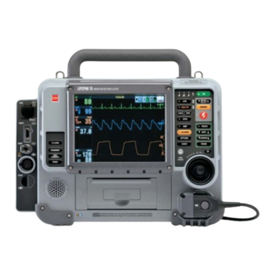
Physio Control LIFEPAK 15 Manual
Monitor defibrillator co2 upgrade
Hide thumbs
Also See for LIFEPAK 15:
- Service manual (527 pages) ,
- Operating instructions manual (285 pages) ,
- Upgrade manual (52 pages)
Advertisement
Quick Links
Title
LIFEPAK 15 Monitor Defibrillator CO2 Upgrade
Doc Type
Service Process Document
Doc State
Released
This document is electronically signed in the Physio-Control, Inc. Product Lifecycle Management (PLM) System. Approvals can be
obtained from the PLM system which displays the selected approvers, their approval roles, and approval dates.
PROPRIETARY AND CONFIDENTIAL DOCUMENT FOR PHYSIO-CONTROL, INC. USE ONLY. This document is property of Physio-
Control and may not be used, reproduced, published or disclosed to others without authorization from Physio-Control.
Attachments (Optional):
Create field service update of the LIFEPAK 15 Monitor/Defibrillator to add CO2 monitoring capability
Doc ID
3308217
State Date
Change Description
Page
1 of 33
Doc Rev
A
09/08/2011
Owner
Qty
Pages
Corporate
Page
Sequencing
Advertisement

Related Manuals for Physio Control LIFEPAK 15


Summary of Contents for Physio Control LIFEPAK 15
- Page 1 PROPRIETARY AND CONFIDENTIAL DOCUMENT FOR PHYSIO-CONTROL, INC. USE ONLY. This document is property of Physio- Control and may not be used, reproduced, published or disclosed to others without authorization from Physio-Control. Owner Corporate Attachments (Optional): Pages Page Sequencing Change Description Create field service update of the LIFEPAK 15 Monitor/Defibrillator to add CO2 monitoring capability...
- Page 2 As a prerequisite, only personnel that have completed LIFEPAK 15 monitor/defibrillator repair training are allowed to perform this upgrade on a LIFEPAK 15 device. An individual will be considered fully trained when they meet the prerequisite, and read and understand this document.
- Page 3 Title LIFEPAK 15 Monitor Defibrillator CO2 Upgrade Page 3 of 33 Doc Type Service Process Document Doc ID 3308217 Doc Rev Doc State Released State Date 09/08/2011 Materials Required: Part Number Description 3207813-XXX (V1) LABEL SET-(configured per kit) 3305642-XXX (V2) LABEL SET-(configured per kit)
- Page 4 Verify that device’s serial number label matches the serial number listed in the upgrade kit documentation. 2. Initial Power-Up Check Install a fully charged battery onto the LIFEPAK 15 Monitor/Defibrillator. Press the ON key. Verify that the device powers up with no service indicator light. If the service indicator light is illuminated, do not proceed with this upgrade, and repair per the appropriate LIFEPAK 15 Monitor/Defibrillator repair process.
- Page 5 Title Page LIFEPAK 15 Monitor Defibrillator CO2 Upgrade 5 of 33 Doc Type Service Process Document Doc ID 3308217 Doc Rev Doc State Released State Date 09/08/2011 Disassembling the Case If applicable, remove carrying case. Remove all cables and patient connections, and then remove the batteries.
- Page 6 Title Page LIFEPAK 15 Monitor Defibrillator CO2 Upgrade 6 of 33 Doc Type Service Process Document Doc ID 3308217 Doc Rev Doc State Released State Date 09/08/2011 Disassembling the Case (continued) Remove Screws Lay the defibrillator face down on a protective...
- Page 7 Title Page LIFEPAK 15 Monitor Defibrillator CO2 Upgrade 7 of 33 Doc Type Service Process Document Doc ID 3308217 Doc Rev Doc State Released State Date 09/08/2011 Disassembling the Case (continued) Disconnect the P2 system/interface flex cable connector (W04) from the system PCB in the rear case.
- Page 8 4.12 Before continuing any further, discharge the energy storage capacitor using the discharge tool (see LIFEPAK 15 service manual section ‘Capacitor Discharging Procedure’). NOTE: You may need to disconnect the P51 connector of W20 from the therapy PCB to gain access to discharge points.
- Page 9 Title Page LIFEPAK 15 Monitor Defibrillator CO2 Upgrade 9 of 33 Doc Type Service Process Document Doc ID 3308217 Doc Rev Doc State Released State Date 09/08/2011 Removing the System (A01)/Therapy (A04) PCB Disconnect J1 Assembly PWR/ SYS Cable Disconnect the connectors on the system PCB...
- Page 10 Title Page LIFEPAK 15 Monitor Defibrillator CO2 Upgrade 10 of 33 Doc Type Service Process Document Doc ID 3308217 Doc Rev Doc State Released State Date 09/08/2011 Removing the System (A01)/Therapy (A04) PCB Assembly (continued) Remove the seven screws (202253-761) and one screw with washer (3207337-312) that secured the system PCB to the rear case.
- Page 11 Title Page LIFEPAK 15 Monitor Defibrillator CO2 Upgrade 11 of 33 Doc Type Service Process Document Doc ID 3308217 Doc Rev Doc State Released State Date 09/08/2011 Removing the System (A01)/Therapy (A04) PCB Assembly (continued) Disconnect Disconnect Continue lifting the assembly. Disconnect the...
- Page 12 Title Page LIFEPAK 15 Monitor Defibrillator CO2 Upgrade 12 of 33 Doc Type Service Process Document Doc ID 3308217 Doc Rev Doc State Released State Date 09/08/2011 Removing the OEM PCB (A06) Disconnect Power Therapy Cable (W02) from J8 on the power PCB.
- Page 13 Title Page LIFEPAK 15 Monitor Defibrillator CO2 Upgrade 13 of 33 Doc Type Service Process Document Doc ID 3308217 Doc Rev Doc State Released State Date 09/08/2011 Removing the Transfer Relay Assembly (A13) Remove Screws Remove the two mounting screws from the...
- Page 14 Title Page LIFEPAK 15 Monitor Defibrillator CO2 Upgrade 14 of 33 Doc Type Service Process Document Doc ID 3308217 Doc Rev Doc State Released State Date 09/08/2011 Removing the OEM Modules bracket assembly Remove Remove the three mounting bracket screws.
- Page 15 Title Page LIFEPAK 15 Monitor Defibrillator CO2 Upgrade 15 of 33 Doc Type Service Process Document Doc ID 3308217 Doc Rev Doc State Released State Date 09/08/2011 Removing the Parameter Bezel Disconnect J12 PWR/Contact Disconnect the power/contact PCB (W05) from cable (W05) the power board J12.
- Page 16 Title Page LIFEPAK 15 Monitor Defibrillator CO2 Upgrade 16 of 33 Doc Type Service Process Document Doc ID 3308217 Doc Rev Doc State Released State Date 09/08/2011 10. Installing the CO2 Inlet Connector Cable (W28) CO2 Inlet Connector 10.1 Set the CO2 connector adapter (3012119) in Location place on the face of the bezel.
- Page 17 Title Page LIFEPAK 15 Monitor Defibrillator CO2 Upgrade 17 of 33 Doc Type Service Process Document Doc ID 3308217 Doc Rev Doc State Released State Date 09/08/2011...
- Page 18 Title Page LIFEPAK 15 Monitor Defibrillator CO2 Upgrade 18 of 33 Doc Type Service Process Document Doc ID 3308217 Doc Rev Doc State Released State Date 09/08/2011 11. Installing the Parameter Bezel Route CO2 Inlet Cable Observe the following: and Tubing around ...
- Page 19 Title Page LIFEPAK 15 Monitor Defibrillator CO2 Upgrade 19 of 33 Doc Type Service Process Document Doc ID 3308217 Doc Rev Doc State Released State Date 09/08/2011 12. Installing the CO2 (A23) Modules OEM/CO2 Screw To install the CO2 option:...
- Page 20 Title Page LIFEPAK 15 Monitor Defibrillator CO2 Upgrade 20 of 33 Doc Type Service Process Document Doc ID 3308217 Doc Rev Doc State Released State Date 09/08/2011 12. Installing the CO2 (A23) Modules (continued) 12.4 Route the CO2 tubing and CO2 adapter cable as shown.
- Page 21 Title Page LIFEPAK 15 Monitor Defibrillator CO2 Upgrade 21 of 33 Doc Type Service Process Document Doc ID 3308217 Doc Rev Doc State Released State Date 09/08/2011 12. Installing the CO2 (A23) Modules (continued) 12.7 Place the OEM bracket into rear case and secure with the three new mounting screws (3207337-312), torque to 6.8 inlb.
- Page 22 Title Page LIFEPAK 15 Monitor Defibrillator CO2 Upgrade 22 of 33 Doc Type Service Process Document Doc ID 3308217 Doc Rev Doc State Released State Date 09/08/2011 13. Installing the OEM PCB (A06) 13.1 Lift the tab at the upper left corner of the OEM...
- Page 23 Title Page LIFEPAK 15 Monitor Defibrillator CO2 Upgrade 23 of 33 Doc Type Service Process Document Doc ID 3308217 Doc Rev Doc State Released State Date 09/08/2011 13. Installing the OEM PCB (A06) (continued) Power/System Power/Contact Cable 3207692 Cable 3207692 13.8 Connect the power/contact cable (W05) to the...
- Page 24 Title Page LIFEPAK 15 Monitor Defibrillator CO2 Upgrade 24 of 33 Doc Type Service Process Document Doc ID 3308217 Doc Rev Doc State Released State Date 09/08/2011 14. Installing the Transfer Relay Assembly (A13) 6.8 In-Lb Screw 14.1 Place the transfer relay assembly into the rear...
- Page 25 Title Page LIFEPAK 15 Monitor Defibrillator CO2 Upgrade 25 of 33 Doc Type Service Process Document Doc ID 3308217 Doc Rev Doc State Released State Date 09/08/2011 15. Installing the System (A01)/Therapy (A04) PCB Connect J4 USB Assembly Flex (W14) ...
- Page 26 Title Page LIFEPAK 15 Monitor Defibrillator CO2 Upgrade 26 of 33 Doc Type Service Process Document Doc ID 3308217 Doc Rev Doc State Released State Date 09/08/2011 15. Installing the System (A01)/Therapy (A04) PCB Assembly (continued) 15.7 Connect the 5-pin connector from the A13 - transfer relay P21 to J21 of the therapy PCB.
- Page 27 Title Page LIFEPAK 15 Monitor Defibrillator CO2 Upgrade 27 of 33 Doc Type Service Process Document Doc ID 3308217 Doc Rev Doc State Released State Date 09/08/2011 15. Installing the System (A01)/Therapy (A04) PCB Assembly (continued) 15.9 Connect the W20 - flex cable from the therapy PCB J51 to the biphasic PCB at J106.
- Page 28 Title Page LIFEPAK 15 Monitor Defibrillator CO2 Upgrade 28 of 33 Doc Type Service Process Document Doc ID 3308217 Doc Rev Doc State Released State Date 09/08/2011 15. Installing the System (A01)/Therapy (A04) PCB Assembly (continued) Connect J6 ECG 15.12 Connect the W07 - ECG cable from the cable (W07) parameter bezel to J6 of the system PCB.
- Page 29 Title Page LIFEPAK 15 Monitor Defibrillator CO2 Upgrade 29 of 33 Doc Type Service Process Document Doc ID 3308217 Doc Rev Doc State Released State Date 09/08/2011 16. Reassembling the Case To reassemble the case halves: 16.1 Position the front case over the rear case.
- Page 30 Title Page LIFEPAK 15 Monitor Defibrillator CO2 Upgrade 30 of 33 Doc Type Service Process Document Doc ID 3308217 Doc Rev Doc State Released State Date 09/08/2011 16. Reassembling the Case (continued) 16.6 Install 14 new screws (201407-069), torque to 10.0 in-lb using a P2 bit.
- Page 31 Title Page LIFEPAK 15 Monitor Defibrillator CO2 Upgrade 31 of 33 Doc Type Service Process Document Doc ID 3308217 Doc Rev Doc State Released State Date 09/08/2011 17. Installing the Parameter Bezel Label Set 17.1 Use a new parameter bezel label. Apply the...
- Page 32 3306808 = Version 2 (V2) LIFEPAK 15 Note: Do not install V1 LIFEPAK 15 software on a device that already has V2 software installed. 18.2.2 Install device software that is specified on the Unit Barcode Traveler (UBT) or kit packing list. (See V2 software information in previous step).
- Page 33 For more information about monitoring channels setup, refer to LIFEPAK 15 setup options 3306226. Perform PIP/TCP Complete Performance Inspection Procedure (PIP) for a LIFEPAK 15 device for all the features that are installed into the device. Use LIFEPAK 15 V1/V2 Service Manual, Manual PIP/TCP procedure or CAPIP test Document the Upgrade (International Service –...
Need help?
Do you have a question about the LIFEPAK 15 and is the answer not in the manual?
Questions and answers