Sign In
Upload
Manuals
Brands
JVA Manuals
Power Supply
Z114
JVA Z114 Manuals
Manuals and User Guides for JVA Z114. We have
3
JVA Z114 manuals available for free PDF download: Installer Manual, Manual, Installation And User Manual
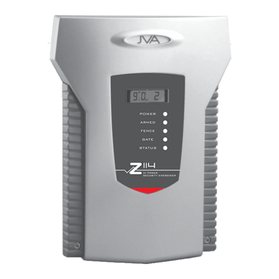
JVA Z114 Manual (48 pages)
ELECTRIC FENCE SYSTEMS
Brand:
JVA
| Category:
Power Supply
| Size: 2 MB
Table of Contents
Table of Contents
1
Introduction
4
Features and Benefits
5
More Features
5
Specifications
6
Description
7
JVA Z114 - Exterior
7
Front Panel Status Lights
7
Front Panel LCD Display
8
Inputs and Outputs
8
Status Codes
8
Keypad (Optional)
8
Z Series Models
8
Keypad (Optional)
9
Internal Beeper/Keypad Beeper
9
Programmable Options
9
Arm Input (Control Input 1) and Key Switch
9
Gate Input (Control Input 2)
9
Low Power Mode
10
Group Simultaneous Pulse Feature
10
Remote Control Unit (Optional)
10
Cabling
10
Lightning Protection
10
Earth Loop Monitoring
11
Noise and Interference
11
PC Control
11
Web Server
11
Installation
12
Installation Steps
12
JVA Z114 - Interior Configuration
13
Examples of Fence (High Voltage) Wiring Diagrams
14
Control
15
Turning to Low Power Mode
15
When an Alarm Occurs
15
Changing the PIN Number
16
Standby Battery
16
Status Light
16
Technical Information
17
Power Options
18
Status Codes
18
Configuring a Z114 to Run in Bi-Polar Mode
19
Jumpers
19
Installation Programming Options
20
Programming Mode
20
To Exit Programming Mode
20
Changing the Installer PIN
20
Changing an Option
20
Programming Options in Brief
21
Programming Options in Detail
22
Power Level (01X#)
22
Low Power Level (02X#)
22
Fence Alarm Voltage (03X#)
23
Low Power Alarm Level (05X#)
23
Missed Pulse Count (06X#)
23
Battery Alarm Voltage (07X#)
24
Siren on Time (08X#)
24
Siren off Time (09X#)
24
Siren Cycles (10X#)
25
Input Type (11X#)
25
Input 2 Function (12X#)
25
Gate Entry/Exit Delay (13X#)
25
Chime Mode (14X#)
26
Binary Options (16X#)
26
Anti-Bridging Threshold (17X#)
27
Binary Options 2 (18X#)
27
Auto Re-Arm Time (20X#)
28
Relay Functions
28
Group Mode (26X#)
29
Jva Z114 Lcd Keypad Features
30
Keypad Status Leds
30
Arming/Disarming the Fence Using the Keypad
30
Menus
31
Keypad Status Display
31
Changing the Keypad Messages and Address
31
To Exit Keypad Programming
32
Notes Regarding Keypad Configuration
33
Connecting Multiple Keypads to a System
33
Summary of LCD Keypad Functions
34
Remote Control Unit
35
Features
35
Installation
36
Operation and Configuration
36
Standard Requirements for Security Electric Fences
37
Definitions
37
General Requirements for Electric Fences
37
Particular Requirements for Electric Animal Fences in Australia
39
Installation of Electric Security Fences
39
General
39
Location of Electric Security Fence
39
Prohibited Zone for Pulsed Conductors
40
Separation between Electric Fence and Physical Barrier
41
Prohibited Mounting
42
Operation of Electric Security Fence
42
Appendix A: Group Simultaneous Pulse Feature
43
Group Simultaneous Pulse Feature
43
Group Mode Programming (26X#)
43
Group Linking Via the Keypad "Bus
44
Advertisement
JVA Z114 Installation And User Manual (48 pages)
HI POWER SECURITY ENERGIZER
Brand:
JVA
| Category:
Power Supply
| Size: 3 MB
Table of Contents
Table of Contents
3
Introduction
5
Features and Benefits
6
More Features
6
Specifications
7
Description
8
JVA Z114 - Exterior
8
Front Panel Status Lights
8
Front Panel Lcd Display
9
Inputs and Outputs
9
Status Codes
9
Keypad (Optional)
9
Z Series Models
9
Keypad (Optional)
10
Internal Beeper/Keypad Beeper
10
Programmable Options
10
Arm Input (Control Input 1) and Key Switch
10
Gate Input (Control Input 2)
10
Low Power Mode
11
Group Simultaneous Pulse Feature
11
Remote Control Unit (Optional)
11
Cabling
11
Lightning Protection
11
Earth Loop Monitoring
12
Noise and Interference
12
Pc Control
12
Web Server
12
Installation
13
Installation Steps
13
JVA Z114 - Interior Configuration
14
Examples of Fence (High Voltage) Wiring Diagrams
15
Control
16
Turning to Low Power Mode
16
When an Alarm Occurs
16
To Silence the Alarm
17
Changing the Pin Number
17
Standby Battery
17
Status Light
17
Technical Information
18
Power Options
19
Status Codes
19
Jumpers
20
Configuring a Z114 to Run in Bi-Polar Mode
20
Installation Programming Options
21
Programming Mode
21
To Exit Programming Mode
21
Changing the Installer Pin
21
Changing an Option
21
Programming Options in Brief
22
Programming Options in Detail
23
Power Level (01X#)
23
Low Power Level (02X#)
23
Fence Alarm Voltage (03X#)
24
Low Power Alarm Level (05X#)
24
Missed Pulse Count (06X#)
24
Battery Alarm Voltage (07X#)
25
Siren on Time (08X#)
25
Siren off Time (09X#)
25
Siren Cycles (10X#)
26
Input Type (11X#)
26
Input 2 Function (12X#)
26
Gate Entry/Exit Delay (13X#)
26
Chime Mode (14X#)
27
Binary Options (16X#)
27
Anti-Bridging Threshold (17X#)
28
Binary Options 2 (18X#)
28
Auto Re-Arm Time (20X#)
29
Relay Functions
29
Group Mode (26X#)
30
JVA Z114 Lcd Keypad Features
31
Keypad Status Leds
31
Arming/Disarming the Fence Using the Keypad
31
Menus
31
Keypad Status Display
32
Changing the Keypad Messages and Address
32
To Exit Keypad Programming
33
Connecting Multiple Keypads to a System
33
Notes Regarding Keypad Configuration
34
Summary of Lcd Keypad Functions
35
Remote Control Unit
36
Features
36
Installation
37
Operation and Configuration
37
Appendix A Group Simultaneous Pulse Feature
38
Group Simultaneous Pulse Feature
38
Group Mode Programming (26X#)
38
Group Linking Via the Keypad "Bus
39
Appendix B Rsa Legal and Safety Requirements for a Security Electric Fence
40
JVA Z114 Installer Manual (52 pages)
Single Zone Energizers
Brand:
JVA
| Category:
Power Supply
| Size: 3 MB
Table of Contents
Table of Contents
3
1 Introduction
5
Glossary
5
2 Features
6
Power
6
Control/Monitoring
6
Safety
8
Reliability
8
3 Specifications
9
Z11 Specifications Table
9
Z13 Specifications Table
9
Z14/Z14R Specification Table
10
Z18 Specification Table
10
Z114 Specification Table
11
Notes for All Z-Series Energizers
11
4 Description
12
Z-Series Exterior
12
High Voltage Terminals
13
LCD Voltage Display
13
Status LED Lights
14
4-Line LCD Keypad (PTE0240)
15
Internal Beeper/Keypad Beeper
27
Cabling
27
Lightning Protection
27
Monitor Earth
27
Noise and Interference
27
Programmable Options
28
Low Power Mode
28
Control Inputs
28
Groups
28
5 Installation
29
Installation Steps
29
Example Fence Wiring Diagrams
30
6 Operation
32
Arm/Disarm Control
32
When an Alarm Occurs
32
To Silence the Alarm
33
Standby Battery
33
Error (Service) Light
33
7 Technical Information
34
Low Voltage Terminals
34
Power Options
36
Battery Information
36
Leds
36
Status LED Error Codes
36
Jumpers
37
Start-Up Events
37
Multiple Keypads
38
Tamper Circuit (Z14R, Z18 and Z114)
38
8 Sector Setup Tests and Adjustment
39
Introduction
39
Basic Fence Tests
39
Fault Condition Tests
40
9 Legal and Safety Requirements for Electric Fences
41
APPENDIX A: Group Simultaneous Pulse Feature
42
APPENDIX B: Pulse Synchronization
47
Warranty
49
Advertisement
Advertisement
Related Products
JVA Z28
JVA Z Series
JVA Z18
JVA Z11
JVA Z13
JVA ZM20
JVA Z14R
JVA Z14
JVA Z25
JVA ZM1
JVA Categories
Power Supply
Measuring Instruments
Monitor
Security System
Inverter
More JVA Manuals
Login
Sign In
OR
Sign in with Facebook
Sign in with Google
Upload manual
Upload from disk
Upload from URL