Table of Contents
Advertisement
Quick Links
Advertisement
Table of Contents

Subscribe to Our Youtube Channel
Related Manuals for YASKAWA IM 208-1DPx1


Summary of Contents for YASKAWA IM 208-1DPx1
- Page 1 VIPA System 200V IM | Manual HB97E_IM | 208-1DPx1 | Rev. 14/05...
- Page 2 Copyright © VIPA GmbH. All Rights Reserved. This document contains proprietary information of VIPA and is not to be disclosed or used except in accordance with applicable agreements. This material is protected by the copyright laws. It may not be reproduced, distributed, or altered in any fashion by any entity (either internal or external to VIPA), except in accordance with applicable agreements, contracts or licensing, without the express written consent of VIPA and the business management owner of the material.
-
Page 3: Table Of Contents
Manual VIPA System 200V Contents Contents About this manual ..................1 Safety information ..................2 Chapter 1 Basics and Assembly ............. 1-1 Safety Information for Users..............1-2 System conception ................1-3 Dimensions ..................1-5 Installation .................... 1-7 Demounting and module exchange ............ 1-11 Wiring.................... - Page 4 Contents Manual VIPA System 200V HB97E - IM - RE_208-1DPx1 - Rev. 14/05...
-
Page 5: About This Manual
Manual VIPA System 200V About this manual About this manual This manual describes the System 200V PROFIBUS DP master modules IM 208-1DPx1 from VIPA. Here you may find every information for commissioning and operation. Overview Chapter 1: Basics and Assembly The focus of this chapter is on the introduction of the VIPA System 200V. - Page 6 Manual VIPA System 200V Objective and This manual describes the System 200V PROFIBUS DP master modules IM 208-1DPx1 from VIPA. It contains a description of the construction, contents project implementation and usage. This manual is part of the documentation package with order number...
-
Page 7: Safety Information
Manual VIPA System 200V Safety information Safety information The IM 208DP is constructed and produced for: Applications conforming with • all VIPA System 200V components specifications • communication and process control • general control and automation applications • industrial applications •... - Page 8 Safety information Manual VIPA System 200V HB97E - IM - RE_208-1DPx1 - Rev. 14/05...
-
Page 9: Chapter 1 Basics And Assembly
Manual VIPA System 200V Chapter 1 Basics and Assembly Chapter 1 Basics and Assembly Overview The focus of this chapter is on the introduction of the VIPA System 200V. Here you will find the information required to assemble and wire a controller system consisting of System 200V components. -
Page 10: Safety Information For Users
Chapter 1 Basics and Assembly Manual VIPA System 200V Safety Information for Users Handling of VIPA modules make use of highly integrated components in MOS- electrostatic Technology. These components are extremely sensitive to over-voltages sensitive modules that can occur during electrostatic discharges. The following symbol is attached to modules that can be destroyed by electrostatic discharges. -
Page 11: System Conception
Manual VIPA System 200V Chapter 1 Basics and Assembly System conception Overview The System 200V is a modular automation system for assembly on a 35mm profile rail. By means of the peripheral modules with 4, 8 and 16 channels this system may properly be adapted matching to your automation tasks. - Page 12 Chapter 1 Basics and Assembly Manual VIPA System 200V Power supplies With the System 200V the DC 24V power supply can take place either externally or via a particularly for this developed power PS 207/2 supply. The power supply may be mounted on the 100-240V AC profile rail together with the System 200V 550-230mA...
-
Page 13: Dimensions
Manual VIPA System 200V Chapter 1 Basics and Assembly Dimensions Dimensions 1tier width (HxWxD) in mm: 76 x 25.4 x 74 Basic enclosure 2tier width (HxWxD) in mm: 76 x 50.8 x 74 Installation dimensions Installed and wired dimensions In- / Output 85 mm 84 mm modules... - Page 14 Chapter 1 Basics and Assembly Manual VIPA System 200V Function modules/ 89 mm 88 mm Extension modules 85 mm 84,46 mm 11 mm 4,66 mm CPUs (here with 91 mm 89 mm EasyConn from 85 mm VIPA) 11 mm 5 mm 12 cm 125 mm HB97E - IM - RE_208-1DPx1 - Rev.
-
Page 15: Installation
Manual VIPA System 200V Chapter 1 Basics and Assembly Installation General The modules are each installed on a 35mm profile rail and connected via a bus connector. Before installing the module the bus connector is to be placed on the profile rail before. Profile rail For installation the following 35mm profile rails may be used: 35 mm... - Page 16 Chapter 1 Basics and Assembly Manual VIPA System 200V Installation on a The following figure shows the installation of a 4tier width bus connector in profile rail a profile rail and the slots for the modules. The different slots are defined by guide rails. Head module (double width) Head module...
- Page 17 Manual VIPA System 200V Chapter 1 Basics and Assembly Assembly possibilities hoizontal assembly vertical Please regard the allowed environmental temperatures: assembly • horizontal assembly: from 0 to 60°C • vertical assembly: from 0 to 40°C • lying assembly: from 0 to 40°C The horizontal assembly always starts at the left side with lying assembly a head module, then you install the peripheral modules...
- Page 18 Chapter 1 Basics and Assembly Manual VIPA System 200V Assembly procedure • Install the profile rail. Make sure that a clearance of at least 60mm exists above and 80mm below the middle of the profile rail. • Press the bus connector into the profile rail until it clips securely into place and the bus-connectors look out from the profile rail.
-
Page 19: Demounting And Module Exchange
Manual VIPA System 200V Chapter 1 Basics and Assembly Demounting and module exchange • Remove if exists the wiring to the module, by pressing both locking lever on the connector and pulling the connector. • The casing of the module has a spring loaded clip at the bottom by which the module can be removed. -
Page 20: Wiring
Chapter 1 Basics and Assembly Manual VIPA System 200V Wiring Overview Most peripheral modules are equipped with a 10pole or a 18pole connector. This connector provides the electrical interface for the signaling and supply lines of the modules. The modules carry spring-clip connectors for interconnections and wiring. The spring-clip connector technology simplifies the wiring requirements for signaling and power cables. - Page 21 Manual VIPA System 200V Chapter 1 Basics and Assembly Wiring procedure • Install the connector on the module until it locks with an audible click. For this purpose you press the two clips together as shown. The connector is now in a permanent position and can easily be wired. The following section shows the wiring procedure from top view.
-
Page 22: Installation Guidelines
Chapter 1 Basics and Assembly Manual VIPA System 200V Installation guidelines General The installation guidelines contain information about the interference free deployment of System 200V systems. There is the description of the ways, interference may occur in your control, how you can make sure the electromagnetic digestibility (EMC), and how you manage the isolation. - Page 23 Manual VIPA System 200V Chapter 1 Basics and Assembly Basic rules for In the most times it is enough to take care of some elementary rules to guarantee the EMC. Please regard the following basic rules when installing your PLC. •...
- Page 24 Chapter 1 Basics and Assembly Manual VIPA System 200V Isolation of Electrical, magnetically and electromagnetic interference fields are conductors weakened by means of an isolation, one talks of absorption. Via the isolation rail, that is connected conductive with the rack, interference currents are shunt via cable isolation to the ground.
-
Page 25: General Data
Manual VIPA System 200V Chapter 1 Basics and Assembly General data • Profile rail 35mm Structure/ • Peripheral modules with recessed labelling dimensions • Dimensions of the basic enclosure: 1tier width: (HxWxD) in mm: 76x25.4x74 in inches: 3x1x3 2tier width: (HxWxD) in mm: 76x50.8x74 in inches: 3x2x3 •... - Page 26 Chapter 1 Basics and Assembly Manual VIPA System 200V 1-18 HB97E - IM - RE_208-1DPx1 - Rev. 14/05...
-
Page 27: Chapter 2 Hardware Description
Manual VIPA System 200V Chapter 2 Hardware description Chapter 2 Hardware description Overview Here the hardware components of the IM 208-1DPx1 are described. The technical data are at the end of the chapter. Contents Topic Page Chapter 2 Hardware description............2-1 Properties..................... -
Page 28: Properties
Chapter 2 Hardware description Manual VIPA System 200V Properties IM 208DP The System 200V PROFIBUS DP master modules from VIPA are available 208-1DPx1 with RS485 as well as with FO connector. • Class 1 PROFIBUS DP master • 125 DP slaves (16 at DPO) connectable to one DP master •... -
Page 29: Structure
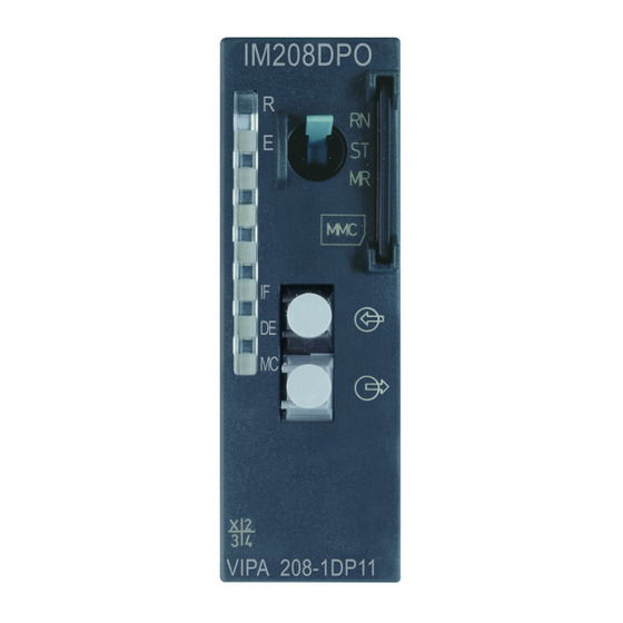
Manual VIPA System 200V Chapter 2 Hardware description Structure Operating mode switch IM 208 DP Front view RUN/STOP IM 208DP LED status indicators Slot for memory card RS485 interface VIPA 208-1DP01 Interface RS485 reserved RxD/TxD-P (line B) n. c. RxD/TxD-N (line A) n.c. - Page 30 Chapter 2 Hardware description Manual VIPA System 200V Operating mode switch IM 208 DPO Front view RUN/STOP IM 208DPO LED status indicators Slot for memory card FO interface VIPA 208-1DP11 Interface FOL interface The IM 208DPO is connected to PROFIBUS by a FOL (fiber optic link) interface.
- Page 31 Manual VIPA System 200V Chapter 2 Hardware description The module carries a number of LEDs that are available for diagnostic LEDs purposes on the bus and for displaying the local status. The following table explains the different colors of the diagnostic LEDs. Label Color Description...
-
Page 32: Technical Data
Chapter 2 Hardware description Manual VIPA System 200V Technical data 208-1DP01 Order no. 208-1DP01 Type IM 208DP, PROFIBUS-DP master Current consumption/power loss Current consumption from backplane bus 450 mA Power loss Status information, alarms, diagnostics Status display Interrupts yes, parameterizable Process alarm yes, parameterizable Diagnostic interrupt... - Page 33 Manual VIPA System 200V Chapter 2 Hardware description 208-1DP11 Order no. 208-1DP11 Type IM 208DPO, PROFIBUS- DP master FO interface Current consumption/power loss Current consumption from backplane bus 450 mA Power loss Status information, alarms, diagnostics Status display Interrupts yes, parameterizable Process alarm yes, parameterizable Diagnostic interrupt...
- Page 34 Chapter 2 Hardware description Manual VIPA System 200V Additional Technical Data IM 208DP PROFIBUS interface VIPA 208-1DP01 Connection 9pin D-type socket Network topology Linear bus, active bus terminator at both ends, tap lines are permitted. Medium Screened twisted pair cable, under certain conditions unscreened lines are permitted.
-
Page 35: Chapter 3 Deployment
Overview This chapter contains a description of the PROFIBUS DP master modules IM 208-1DPx1 under PROFIBUS. A short introduction and presentation of the system is followed by the project design and configuration of the PROFIBUS master modules that are available from VIPA. The chapter concludes with a number of communication examples and the technical data. -
Page 36: Basics Profibus
Chapter 3 Deployment Manual VIPA System 200V Basics PROFIBUS General PROFIBUS is an international standard applicable to an open fieldbus for building, manufacturing and process automation. PROFIBUS defines the technical and functional characteristics of a serial fieldbus system that can be used to create a low (sensor-/actuator level) or medium (process level) performance network of programmable logic controllers. - Page 37 Manual VIPA System 200V Chapter 3 Deployment Master and slaves PROFIBUS distinguishes between active stations (master) and passive stations (slave). Master devices Master devices control the data traffic at the bus. It is also possible to operate with multiple masters on a PROFIBUS. This is referred to as multi- master operation.
- Page 38 Chapter 3 Deployment Manual VIPA System 200V The bus transfer protocol provides two alternatives for the access to the Communication bus: Master with Master communication is also referred to as token-passing procedure. The master token-passing procedure guarantees the accessibility of the bus. The permission to access the bus is transferred between individual devices in the form of a "token".
- Page 39 Manual VIPA System 200V Chapter 3 Deployment • Max. 125 DP slaves at one DP master - max. 32 slaves/segment Restrictions • Max. 16 DPO slaves at one DPO master at 1.5MBaud • You can only install or remove peripheral modules when you have turned the power off! •...
- Page 40 Chapter 3 Deployment Manual VIPA System 200V V-bus cycle A V-bus cycle (V-Bus = VIPA backplane bus) saves all the input data from the modules in the PII and all the output data from the PIQ in the output modules. When the data has been saved the PII is transferred into the ”buffer send”...
- Page 41 Manual VIPA System 200V Chapter 3 Deployment The key feature of version DP-V1 is the extended function for acyclic data Function communication. This forms the requirement for parameterization and Acyclic data calibration of the field devices over the bus during runtime and for the communication introduction of confirmed alarm messages.
- Page 42 Chapter 3 Deployment Manual VIPA System 200V Services Additional available services are shown in following table. Acyclic data More detailed information to the services and the DP-V0/1 communication - communication principles is to find in the PROFIBUS norm IEC 61158. DPM 1 (MSAC-C1) Services for Acyclic data communication between the DPM 1 and Slaves...
- Page 43 Manual VIPA System 200V Chapter 3 Deployment PROFIBUS employs screened twisted pair cable on the basis of the RS485 Data transfer interfaces or a duplex fiber optic link (FO). The data transfer rate of both medium systems is limited to a max. of 12MBaud. For details please refer to the "Assembly and installation guidelines".
-
Page 44: Operating Modes And Start-Up Behavior
Chapter 3 Deployment Manual VIPA System 200V Operating modes and Start-up behavior Power ON The DP master is powered on. The master will change automatically to RUN mode when the operating mode lever is in position RUN and the parameters are valid. STOP In STOP mode the outputs of the allocated slaves will be set to 0 if the parameters are valid. -
Page 45: Deployment Master With A Cpu 21X
Manual VIPA System 200V Chapter 3 Deployment Deployment Master with a CPU 21x Communication Via the IM 208 master modules you may connect up to 125 PROFIBUS DP slaves (up to 16 at DPO) to one System 200V CPU. The master communicates with the slaves and transfers the data areas via the backplane bus into the address area of the CPU. -
Page 46: Project Engineering
Chapter 3 Deployment Manual VIPA System 200V Project engineering Overview There are the following possibilities for project engineering: • Project engineering of the 1. DP master in the System (CPU 21xDPM, IM 208) Project engineering in the hardware configurator from Siemens and transfer via the system data into the CPU. - Page 47 Manual VIPA System 200V Chapter 3 Deployment In the hardware configurator from Siemens your PLC system is projected Project engi- together with the DP master. This "hardware configuration" is to be neering of the 1. transferred via MPI into the CPU. At PowerON, the configuration data is DP master in the transferred to the DP master.
- Page 48 Chapter 3 Deployment Manual VIPA System 200V To be compatible to the Siemens SIMATIC Manager, the System 200V CPU has to be included explicitly. For this, you add a System "VIPA_CPU21x" to the subnet. This system is to find in the hardware catalog at: PROFIBUS DP >...
- Page 49 Manual VIPA System 200V Chapter 3 Deployment If there are further more IM 208 DP master in one system, for each a Project project is to be projected. This project may be transferred to the engineering of corresponding DP master either by MMC or by Green Cable. The Project is further DP master permanently stored in the Flash ROM of the DP master by means of an in the system...
- Page 50 Chapter 3 Deployment Manual VIPA System 200V Export dpm.wld Export your project to a MMC by creating a wld-file. The MMC is then plugged in the according DP master. The Project is permanently stored in the Flash ROM of the DP master by means of an overall reset sequence. After the transfer, you may release the MMC again.
- Page 51 Manual VIPA System 200V Chapter 3 Deployment The PROFIBUS master may be easily configured by means of the VIPA Configuration with WinNCS configuration tool. You may export your project as 2bf-file on a WinNCS MMC res. transfer it via SIP-Tool into the DP master (only at IM 208DP respectively possible).
- Page 52 Chapter 3 Deployment Manual VIPA System 200V There are the following possibilities to transfer the wld- respectively 2bf-file Transfer variants into the DP master: • Transfer via MPI into the CPU (only for the 1 DP master at system) • Transfer via MMC •...
- Page 53 Manual VIPA System 200V Chapter 3 Deployment Transfer via MMC Transfer the wld- respectively the 2bf-file to the MMC by means of a MMC reading device. Plug-in the MMC memory module into your IM 208DP master Turn on the power supply for the System 200V. IM 208 DP Hold the operating mode lever of the PROFIBUS master in position MR until the blinking MC-LED switches to permanent on.
- Page 54 Chapter 3 Deployment Manual VIPA System 200V Transfer via Green The method shown below can only be used at the IM 208DP with RS485- Cable and VIPA interface. The SIP-Tool is a transfer tool. It is supplied together with SIP-Tool WinNCS from VIPA.
- Page 55 Manual VIPA System 200V Chapter 3 Deployment Continued transfer If you like to project the IM 208 PROFIBUS DP master with the SIP-Tool, via Green Cable this is only possible with DP master firmware V4.0.0 and higher and with and VIPA SIP-Tool SIP-Tool Version V1.0.6 and higher.
-
Page 56: Slave Operating Mode
Chapter 3 Deployment Manual VIPA System 200V Slave operating mode Overview Starting with CPU firmware V3.7.2 there is the possibility to use the IM 208DP as DP slave. The Siemens GSD file for the CPU S7-315-2DP is needed for connection to a DP master system. For hardware technical reasons this functionality is not available for the IM 208DPO master with FO. - Page 57 Manual VIPA System 200V Chapter 3 Deployment • Start the Siemens SIMATIC manager. Hardware configuration • Install for CPU 21x project engineering the GSD VIPA_21x.GSD. System 200V • Install for linking the DP master the GSD VIPA04D5.GSD. • Create a new project System 300 and add a profile rail from the hardware catalog.
- Page 58 Chapter 3 Deployment Manual VIPA System 200V • Create a new project System 300 and add a profile rail from the Hardware- configuration hardware catalog. IM 208DP • Insert the CPU 315-2DP. Hardware catalog: Simatic300 > CPU-300 > CPU315-2DP (6ES7 315-2AF03-0AB0 V1.2) •...
- Page 59 Manual VIPA System 200V Chapter 3 Deployment Summary Hardware configuration System 200V (VIPA_21x.GSD required) (0)UR Operating mode CPU 315-2 DP DP master General > Properties PROFIBUS address: 2...125 (which is still unused) General > PROFIBUS PROFIBUS address: 1 CPU 21x Properties IM 208DP I/O periphery Transfer project...
-
Page 60: Overall Reset
Chapter 3 Deployment Manual VIPA System 200V Overall reset General Starting with the firmware version V3.0.6 of the DP masters, you have the possibility to request an overall reset at the DP master. An overall reset clears all data in the Flash-ROM. Execute an overall Turn on the power supply of the System 200V. -
Page 61: Firmware Update
Manual VIPA System 200V Chapter 3 Deployment Firmware update Overview Starting with CPU firmware version 3.3.3 a MMC inside your CPU can be used to update the firmware of CPU an DP master. The latest 2 firmware versions are to find in the service area at www.vipa.de and at the ftp server at ftp.vipa.de. - Page 62 Chapter 3 Deployment Manual VIPA System 200V • Get the RUN-STOP lever of your CPU in position STOP. Transfer firmware from MMC into DP • Turn off the voltage supply. master • Plug the MMC with the firmware into the CPU. Please take care of the correct plug-in direction of the MMC.
-
Page 63: Profibus Installation Guidelines
Manual VIPA System 200V Chapter 3 Deployment PROFIBUS installation guidelines • A PROFIBUS DP network may only be built up in linear structure. PROFIBUS in general • PROFIBUS DP consists of minimum one segment with at least one master and one slave. •... - Page 64 Chapter 3 Deployment Manual VIPA System 200V • The bus must be terminated at both ends. Electrical system • Masters and slaves may be installed in any combination. • Any FO master may only be installed on an electrical system by means Combined system of an Optical Link Plug, i.e.
- Page 65 Manual VIPA System 200V Chapter 3 Deployment Bus connection The following picture illustrates the terminating resistors of the respective start and end station. Master Slave Slave RxD/TxD-P(B) RxD/TxD-P(B) RxD/TxD-P(B) RxD/TxD-N(A) RxD/TxD-N(A) RxD/TxD-N(A) Shield Shield Shield Note! The PROFIBUS line has to be terminated with its ripple resistor. Please make sure to terminate the last participants on the bus at both ends by activating the terminating resistor.
- Page 66 Chapter 3 Deployment Manual VIPA System 200V Note! To connect this EasyConn plug, please use the standard PROFIBUS cable type A (EN50170). Starting with release 5 you also can use highly flexible bus cable: Lapp Kabel order no.: 2170222, 2170822, 2170322. With the order no.
- Page 67 Manual VIPA System 200V Chapter 3 Deployment PROFIBUS with The fiber optic cable/optical waveguide (FO) transfers signals by means of FO link electromagnetic waves at optical frequencies. Total reflection will occur at the point where the coating of the fiber optic cable meets the core since the refractive index of this material is lower than that of the core.
- Page 68 Chapter 3 Deployment Manual VIPA System 200V Fiber optic cabling The VIPA fiber optic PROFIBUS coupler employs dual core plastic fiber under PROFIBUS optic cable as the communication medium. Please keep the following points in mind when you connect your PROFIBUS FO coupler: predecessor and successor must always be connected by means of a dual core FO cable.
- Page 69 Manual VIPA System 200V Chapter 3 Deployment FO connector without crimp-type assembly HP order no.: HFBR-4531 Advantages: no special tool required. Connection for predecessor This shell of this type of plug is provided with an integrated strain relief. reception The fiber optic cable is clamped securely when you clip the two sections transmission of the shell together.
- Page 70 Chapter 3 Deployment Manual VIPA System 200V Example for a PROFIBUS network One CPU and The CPU should have a short cycle time to ensure that the data from slave multiple master no. 5 (on the right) is always up to date. This type of structure is only connections suitable when the data from slaves on the slow trunk (on the left) is not critical.
- Page 71 Manual VIPA System 200V Chapter 3 Deployment Multi master Multiple master connections on a single bus in conjunction with a number of system slaves: IM 208 IM 208 IM 253 IM 253 Input/output periphery Input/output periphery IM 253 IM 253 Input/output periphery Input/output periphery Expansion options...
- Page 72 Chapter 3 Deployment Manual VIPA System 200V Optical PROFIBUS IM 208 1,2, IM 253 Input/output periphery IM 253 Input/output periphery IM 253 Input/output periphery IM 253 Input/output periphery Links to other masters via optical Expansion options - slaves optical or electrical links (by means of an optical - slaves electric link plug) are NOT permitted! 3-38...
- Page 73 Manual VIPA System 200V Chapter 3 Deployment Combination of In a combined fiber optical PROFIBUS system only one converter (OLP) optical and may be installed between any two masters! electrical PROFIBUS IM 208 IM 253 Input/output periphery Bus connector RS 485 IM 253 This bus connector is provided to allow connection of an optical (via OLP) or electrical...
-
Page 74: Commissioning
Chapter 3 Deployment Manual VIPA System 200V Commissioning • Assemble your PROFIBUS system. Overview • Configure your master system. • Transfer the configuration into your master. • Connect the master and slave modules with the PROFIBUS. • Turn the power supply on. Installation Assemble your PROFIBUS system using the wanted modules. -
Page 75: Using The Diagnostic Leds
Manual VIPA System 200V Chapter 3 Deployment Using the diagnostic LEDs The following example shows the reaction of the LEDs for different types of network interruption. Master Interruption at position A The PROFIBUS has been interrupted. Interruption at position B Communication via the backplane bus has been interrupted. -
Page 76: Sample Projects For Profibus Communication
Chapter 3 Deployment Manual VIPA System 200V Sample projects for PROFIBUS communication Example 1 Problem The following example describes a communication between a master and a slave system. The master system consists of a CPU 21x (here CPU 214-1BA03) and a DP master IM 208DP. - Page 77 Manual VIPA System 200V Chapter 3 Deployment Engineering To be compatible with the Siemens SIMATIC Manager, you have to IM 208DP execute the following steps for the System 200V: • Start the Hardware configurator from Siemens • Install the GSD-file vipa_21x.gsd •...
- Page 78 Chapter 3 Deployment Manual VIPA System 200V User application For the user application in the CPU, we use the OB35. The OB35 is a time in the CPU OB, where the call cycle is defined in the CPU properties. OB 35 (Time-OB) counter from FFh to 00h remember new counter value transfer new counter value to output byte 0...
- Page 79 Manual VIPA System 200V Chapter 3 Deployment Example 2 Problem This example shows a communication between a CPU 21x (here CPU 214- 1BA03) with IM 208 DP master and a CPU 21xDP (here CPU 214-2BP03). Via this system, counter values should be exchanged via PROFIBUS and monitored at the output module of the respective partner.
- Page 80 Chapter 3 Deployment Manual VIPA System 200V Engineering To be compatible with the STEP 7 projecting tool from Siemens, you have CPU 214 of the to execute the following steps for CPU 214 and DP master: DP master • Start the Hardware configurator from Siemens •...
- Page 81 Manual VIPA System 200V Chapter 3 Deployment User application in The user application in the CPU 21x has 2 tasks to execute, shared the CPU 214 between two OBs: • Test the communication via control byte. Load the input byte from PROFIBUS and monitor the value at the output module.
- Page 82 Chapter 3 Deployment Manual VIPA System 200V Engineering To be compatible with the Siemens SIMATIC Manager, you have to CPU 214DP execute the following steps for the CPU 214DP: • Start the Hardware configurator from Siemens • Install the GSD-file vipa_21x.gsd •...
- Page 83 Manual VIPA System 200V Chapter 3 Deployment User application Like shown above, the user application has 2 tasks, shared between two in the CPU 214DP OBs: • Load the input byte from the PROFIBUS slave and monitor the value at the output module.
- Page 84 Chapter 3 Deployment Manual VIPA System 200V 3-50 HB97E - IM - RE_208-1DPx1 - Rev. 14/05...
Need help?
Do you have a question about the IM 208-1DPx1 and is the answer not in the manual?
Questions and answers