Table of Contents
Advertisement
Quick Links
ADCP-96-806
Issue 4, July 2016
48/96-Port Indoor Fiber Distribution Terminal
Content
1
GENERAL INFORMATION . . . . . . . . . . . . . . . . . . . . . . . . . . . . . . . . . . . . . . . . . . . . . . . . . . . . . . . . . . . . . . . . . . .3
1.1
1.2
2
CABINET INSTALLATION . . . . . . . . . . . . . . . . . . . . . . . . . . . . . . . . . . . . . . . . . . . . . . . . . . . . . . . . . . . . . . . . . . .4
2.1
2.2
3
GROUNDING THE CABINET . . . . . . . . . . . . . . . . . . . . . . . . . . . . . . . . . . . . . . . . . . . . . . . . . . . . . . . . . . . . . . . . .5
4
CABLE INSTALLATION. . . . . . . . . . . . . . . . . . . . . . . . . . . . . . . . . . . . . . . . . . . . . . . . . . . . . . . . . . . . . . . . . . . . .6
4.1
4.2
5
ROUTING CABLE FIBERS AND SPLICING . . . . . . . . . . . . . . . . . . . . . . . . . . . . . . . . . . . . . . . . . . . . . . . . . . . . . . . .9
6
INTERCONNECTIONS . . . . . . . . . . . . . . . . . . . . . . . . . . . . . . . . . . . . . . . . . . . . . . . . . . . . . . . . . . . . . . . . . . . . 10
7
CUSTOMER INFORMATION AND ASSISTANCE . . . . . . . . . . . . . . . . . . . . . . . . . . . . . . . . . . . . . . . . . . . . . . . . . . . 14
INTRODUCTION
This publication provides a description of the 48/96-Port Indoor Fiber Distribution Terminal
(IFDT) plus procedures for installation and operation. The 48/96-Port IFDT provides splicing,
termination, and interconnect functions for fiber optic cables used in indoor applications.
300001720956 Rev C
www.commscope.com
OmniReach® FTTX Solutions
Description . . . . . . . . . . . . . . . . . . . . . . . . . . . . . . . . . . . . . . . . . . . . . . . . . . . . . . . . . . . . . . . . . . . . . .4
Options . . . . . . . . . . . . . . . . . . . . . . . . . . . . . . . . . . . . . . . . . . . . . . . . . . . . . . . . . . . . . . . . . . . . . . . . .4
General Recommendations . . . . . . . . . . . . . . . . . . . . . . . . . . . . . . . . . . . . . . . . . . . . . . . . . . . . . . . . . . .4
Mounting Procedure . . . . . . . . . . . . . . . . . . . . . . . . . . . . . . . . . . . . . . . . . . . . . . . . . . . . . . . . . . . . . . . .4
Securing Cables to the Cabinet Using a Compression Fitting . . . . . . . . . . . . . . . . . . . . . . . . . . . . . . . . . . . .7
Securing Cables to the Cabinet by Lashing. . . . . . . . . . . . . . . . . . . . . . . . . . . . . . . . . . . . . . . . . . . . . . . . .8
Instruction Sheet
© 2016 CommScope. All Rights Reserved.
FTTX
Page
Page 1
Advertisement
Table of Contents

Related Manuals for CommScope OmniReach FTTX


Summary of Contents for CommScope OmniReach FTTX
-
Page 1: Table Of Contents
This publication provides a description of the 48/96-Port Indoor Fiber Distribution Terminal (IFDT) plus procedures for installation and operation. The 48/96-Port IFDT provides splicing, termination, and interconnect functions for fiber optic cables used in indoor applications. 300001720956 Rev C Page 1 © 2016 CommScope. All Rights Reserved. www.commscope.com... - Page 2 Section 7 Updated contact information. Trademark Information CommScope is a registered trademark of CommScope Inc. Admonishments Important safety admonishments are used throughout this manual to warn of possible hazards to persons or equipment. An admonishment identifies a possible hazard and then explains what may happen if the hazard is not avoided.
-
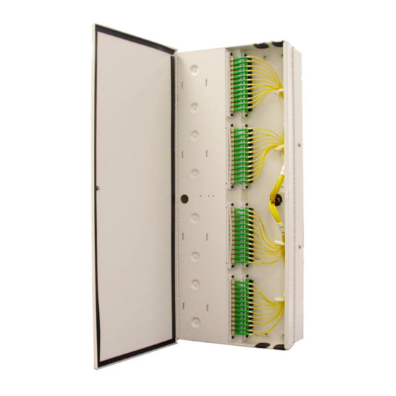
Page 3: General Information
A drawing of a 96-port IFDT equipped with pigtails on both the feeder/provider and distribution/subscriber side is shown in Figure TERMINATION AND INTERCONNECTION 23115-B SPLICE COMPARTMENT COMPARTMENT Figure 1. Typical 96-Port IFDT with Pigtails Installed Page 3 © 2016 CommScope. All Rights Reserved. -
Page 4: Description
2. Mount the plywood backer (not provided) on the wall and firmly secure it to the wall’s interior studs. 3. Attach the template provided with the unit to the plywood backer. The cabinet dimensions are shown in Figure Page 4 © 2016 CommScope. All Rights Reserved. -
Page 5: Grounding The Cabinet
40 inch-lbs (4.5 Nm) of torque. 5. Use a #6 AWG copper wire to connect the cabinet to an approved earth ground source as specified by local code or practice. Avoid sharp bends in the ground wire. Page 5 © 2016 CommScope. All Rights Reserved. -
Page 6: Cable Installation
Cables may enter the cabinet from any of the four openings. TOP CABLE ENTRY PORTS CABLE TIE PLATES CABLE TIE PLATES BOTTOM CABLE 24763-A ENTRY PORTS Figure 4. Cable Entry Ports Page 6 © 2016 CommScope. All Rights Reserved. -
Page 7: Securing Cables To The Cabinet Using A Compression Fitting
Clean if necessary. 6. Adjust cable so approximately 2 inches of the cable sheath extends into the cabinet and then tighten the compression fitting nut to secure the cable to the cabinet. Page 7 © 2016 CommScope. All Rights Reserved. -
Page 8: Securing Cables To The Cabinet By Lashing
Wrap strain relief material around the cable to prevent the cable from being excessively compressed by the cable ties. Use two cable ties to secure the cable to the bracket. Figure 6. Lashing Cables to Cable Tie Down Plate - Typical Example Page 8 © 2016 CommScope. All Rights Reserved. -
Page 9: Routing Cable Fibers And Splicing
TOP ENTRY PIGTAIL ASSEMBLIES FOR TYPICAL ROUTING DISTRIBUTION/SUBSCIRBER CABLE (YELLOW PROTECTIVE JACKET) PIGTAIL ASSEMBLIES FOR FEEDER/PROVIDER CABLE (BLACK PROTECTIVE JACKET) BOTTOM ENTRY 23119-A TYPICAL ROUTING Figure 7. Routing Cable Fibers to Splice Trays Page 9 © 2016 CommScope. All Rights Reserved. -
Page 10: Interconnections
Cable tie mounting blocks are provided separately for managing jumpers within the cabinet. Punch a hole through the soft rubber material covering the selected jumper entry port and then route the jumper into the cabinet. Page 10 © 2016 CommScope. All Rights Reserved. - Page 11 Service is initiated when a patch cord connector is moved from the parking lot to the appropriate feeder/provider port as shown in Figure Page 11 © 2016 CommScope. All Rights Reserved.
- Page 12 SPLICE JUMPER ENTRY PORT TRAYS PARKING FEEDER/PROVIDER PORT DISTRIBUTION/SUBSCRIBER PATCH CORDS DUST CAP (REMOVE) CONNECT DISTRIBUTION/ SUBSCRIBER CONNECTOR PARKING TO FEEDER/PROVIDER PORT PANEL 24411-A Figure 11. Parking IFDT Without Pre-Installed Distribution/Subscriber Pigtails Page 12 © 2016 CommScope. All Rights Reserved.
- Page 13 PORTS (TWO ROWS) 24409-A Figure 12. Non-Parking IFDT Without Pre-Installed Distribution/Subscriber Pigtails 7 TECHNICAL ASSISTANCE Contact the Technical Assistance Center (TAC) for technical question. Call 800.830.5056 or send an email to TAC.Americas@commscope.com. Page 13 © 2016 CommScope. All Rights Reserved.
Need help?
Do you have a question about the OmniReach FTTX and is the answer not in the manual?
Questions and answers