Table of Contents
Advertisement
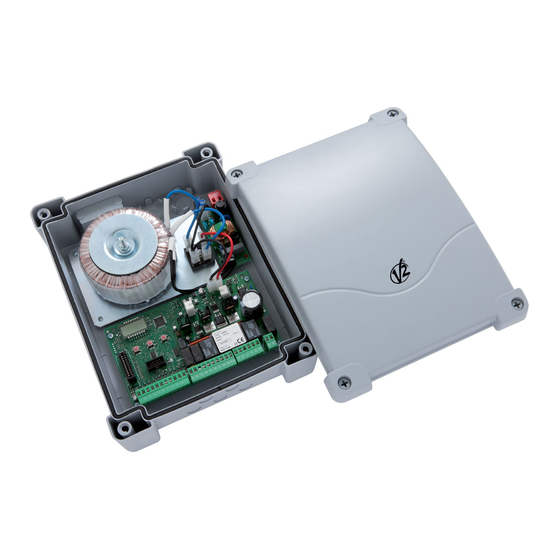
CITY2+
CITY2+L
CITY2+ BC
CENTRALE DI COMANDO (24V) DIGITALE
I
PER CANCELLI AD ANTA E SCORREVOLI
DIGITAL CONTROL UNIT (24V)
GB
FOR LEAF SWING AND SLIDING GATES
ARMOIRE DE COMMANDE NUMÉRIQUE (24V)
F
POUR PORTAILS À VANTAILS ET COULISSANTS
CUADRO DE MANIOBRAS DIGITAL (24V) PARA
E
CANCELAS BATIENTES Y PUERTAS CORREDERAS
ZIS193
IL 291-1
EDIZ. 18/03/2019
Advertisement
Table of Contents

Related Manuals for V2 CITY2+


Summary of Contents for V2 CITY2+
- Page 1 ZIS193 IL 291-1 EDIZ. 18/03/2019 CITY2+ CITY2+L CITY2+ BC CENTRALE DI COMANDO (24V) DIGITALE PER CANCELLI AD ANTA E SCORREVOLI DIGITAL CONTROL UNIT (24V) FOR LEAF SWING AND SLIDING GATES ARMOIRE DE COMMANDE NUMÉRIQUE (24V) POUR PORTAILS À VANTAILS ET COULISSANTS...
-
Page 3: Table Of Contents
INDEX 1 - IMPORTANT REMARKS ............................2 - DECLARATION OF CONFORMITY ......................... 3 - TECHNICAL SPECIFICATIONS ..........................4 - DESCRIPTION OF THE CONTROL UNIT ......................... 5 - INSTALLATION ............................... 5.1 - POWER SUPPLY ............................... 5.2 - MOTORS ................................. 5.3 - ACTIVATION INPUTS ............................5.4 - STOP ................................ -
Page 4: Important Remarks
1 - IMPORTANT REMARKS 2 - DECLARATION OF CONFORMITY For any installation problem please contact our Customer Service V2 S.p.A. hereby declare that CITY2+ products conform to the at the number +39-0172.812411 operating Monday to Friday essential requirements established in the following directives: from 8:30 to 12:30 and from 14:00 to 18:00. -
Page 5: Description Of The Control Unit
UNIT Installation of control unit and safety devices must be carried out with power disconnected. The digital control unit CITY2+ is an innovative V2 product that guarantees a safe and reliable automation of leaf swing or sliding gates. 5.1 - POWER SUPPLY... -
Page 6: Activation Inputs
5.3 - ACTIVATION INPUTS 5.4 - STOP CITY2+ control unit is equipped with two activation inputs For a better safety, you can fit a stop switch that will cause the (START and START P.), whose operation depends on the immediate gate stop when activated. This switch must have a programmed operation modes (see Strtitem of programming normally close contact that will get open in case of operation. -
Page 7: Safety Ribbons
5.6 - SAFETY RIBBONS 5.7 - LOW VOLTAGE LIGHT (24V) The control unit considers two kinds of safety ribbons, depending The CITY2+ controller has a 24 V DC output that allows on the terminal to which they are connected: connections to a load up to 15 W. This output can be used to connect a signal light that indicates Type 1 (fixed) that status of the gate, or for a low voltage flashing light. -
Page 8: Limit Switch And Encoder
5.10 - LIMIT SWITCH AND ENCODER Check that the two pairs of wires have been correctly connected and after installation proceed as follows: The CITY2+ controller can control the gate’s travel using a limit switch and/or an encoder. Enco 1. Disable encoder operation ( menu) CAUTION: The use of these devices is strongly r.AP... -
Page 9: External Aerial
The ADI (Additional Devices Interface) interface of the control unit CITY2+ allows the connection to V2 optional modules. Refer to V2 catalogue or to the technical sheets to see which optional modules with ADI interface are available for this control unit. -
Page 10: Electric Connections
5.14 - ELECTRIC CONNECTIONS Antenna Z1 - Z2 Low voltage light (24V) Antenna shield Motor 1 (OPENING) Opening control for the connection of control Motor 1 (CLOSING) devices with N.O. contact Motor 2 (OPENING) Opening controls for pedestrian access for the Motor 2 (CLOSING) connection of control devices with N.O. - Page 11 CITY2+ MAINS CITY2+L MAINS CITY2+ POW- CITY2+L POW+ BAT- CITY2+BC DOWN MENU OVERLOAD - 31 -...
-
Page 12: Control Panel
6 - CONTROL PANEL 6.1 - USE OF THE DOWN, MENU AND UP KEYS FOR PROGRAMMING When power is on, the control unit checks that display correctly 8.8.8.8 operates by switching on all segments for 1.5 sec. Programming of the functions and times of the controller is Pr 2.4 Firmware version, e.g. -
Page 13: Quick Configuration
7 - QUICK CONFIGURATION This paragraph concerns a quick procedure to set the control unit and set it at work immediately. We recommend following these instructions, in order to check quickly the correct operation of control unit, motor and accessories, and then changing the configuration in case of any non-satisfactory parameter. -
Page 14: Self-Learning Of Working Times
9 - SELF-LEARNING OF WORKING 5. The display shows the value recommended for the obstacle sensor of motor 1. If no operations are performed for 20 TIMES seconds, the controller exits the programming phase without saving the recommended value. This menu allows the automatic learning of the times necessary to 6. -
Page 15: Reading Of Cycle Counter
10 - READING OF CYCLE COUNTER Area 3 is the setup of this latter counter; on first pressing the Up or Down key the current value of the counter is rounded to the thousand, each press after this increases the setting by 1000 units CITY2+ control unit counts the completed opening cycles of the or decreases by 100. -
Page 16: Control Unit Configuration
Control unit time and function programming is made within a CITY2+ special configuration menu, to which you can access and where you can shift through DOWN, MENU and UP keys placed under CITY2+L the display. CITY2+BC -PrG Hold down the MENU key until appears on display, to activate the programming mode while display views the panel. - Page 17 PARAMETER VALUE DESCRIPTION DEFAULT MEMO t.AP1 22.5” Leaf 1 opening time 0.0”-5’00 Adjustable time from 0 seconds to 5 minutes t.AP2 22.5” Leaf 2 opening time 0.0”-5’00 Adjustable time from 0 seconds to 5 minutes. WARNING: if motor 2 is not connected, this time must be set to zero t.APP 6.0”...
- Page 18 PARAMETER VALUE DESCRIPTION DEFAULT MEMO t.ASE 1.0” Lock advance time 0.0”- 1’00 t.ASE While the electric lock is energized, the gate will stay standstill for time, to make its release easier. t.ASE t.SEr In case is lower than , the lock energizing will go on while the doors will start moving.
- Page 19 PARAMETER VALUE DESCRIPTION DEFAULT MEMO SEn1 0.0A Enable the obstacle sensor for motor 1 0.0A - 14.0A This menu allows you to regulate the sensitivity of the obstacle sensor for motor 1. When the current absorbed by the motor exceeds the set value, the controller detects an alarm.
- Page 20 PARAMETER VALUE DESCRIPTION DEFAULT MEMO SPAP PAUS Pedestrian Start during the partial opening phase This menu allows fixing the control unit conduct in case it receives a Pedestrian Start command during the partial opening phase. WARNING: a Start command in any phase of partial opening will cause the total opening;...
- Page 21 PARAMETER VALUE DESCRIPTION DEFAULT MEMO SPiA Low voltage output setup This menu allows you to set the operation of the low voltage output. Not used FLSh Flasher operation (fixed frequency) W.L. Indicator light operation: Indicates the status of the gate in real-time. The type of blinking indicates the four possible conditions: - GATE STOPPED: Light off - GATE IN PAUSE: the light is on, fixed...
- Page 22 PARAMETER VALUE DESCRIPTION DEFAULT MEMO CoS1 Safety ribbon 1 input This menu allows enabling the input for type 1 safety ribbon, that is to say, fixed ribbons Input disabled Input enabled during the opening and disabled during the closure APCh Input enabled in opening and closure CoS2 Safety ribbon 2 input...
-
Page 23: Operation Defects
3. Check whether the fuse is burnt-out, if so replace it with same This kind of defect has no remedy and the control unit must be value. sent to V2 S.p.A. for repair. OVERLOAD led is on Error 2 It means that there is an overload on accessory power supply. - Page 24 • Change the end of stroke sensor or the broken wiring. If the error persists send the control unit to V2 S.p.A. for repair. This means that the ADI module function test failed. • If limit switches have not been connected, check that the FC.En...
- Page 25 V2 S.p.A. Corso Principi di Piemonte 65/67 12035 RACCONIGI CN (ITALY) Tel. +39 0172 812411 - Fax +39 0172 84050 info@v2home.com www.v2home.com...
Need help?
Do you have a question about the CITY2+ and is the answer not in the manual?
Questions and answers