V2 CITY2+ Manual
Hide thumbs
Also See for CITY2+:
- Manual (101 pages) ,
- Instruction manual (25 pages) ,
- Manual (180 pages)
Table of Contents
Advertisement
INDEX
IMPORTANT REMARKS . . . . . . . . . . . . . . . . . . . . . . . . . . . . . . . . . . . . . . . . . . . . . . . . . . . . . . . . . . . . . . . . . . . . . . . . .28
DECLARATION OF CONFORMITY . . . . . . . . . . . . . . . . . . . . . . . . . . . . . . . . . . . . . . . . . . . . . . . . . . . . . . . . . . . . . . . . .28
TECHNICAL SPECIFICATIONS . . . . . . . . . . . . . . . . . . . . . . . . . . . . . . . . . . . . . . . . . . . . . . . . . . . . . . . . . . . . . . . . . . . .28
DESCRIPTION OF THE CONTROL UNIT . . . . . . . . . . . . . . . . . . . . . . . . . . . . . . . . . . . . . . . . . . . . . . . . . . . . . . . . . . . . .28
INSTALLATION . . . . . . . . . . . . . . . . . . . . . . . . . . . . . . . . . . . . . . . . . . . . . . . . . . . . . . . . . . . . . . . . . . . . . . . . . . . . . . .29
POWER SUPPLY . . . . . . . . . . . . . . . . . . . . . . . . . . . . . . . . . . . . . . . . . . . . . . . . . . . . . . . . . . . . . . . . . . . . . . . . . . . . . .29
LOW VOLTAGE OUTPUT . . . . . . . . . . . . . . . . . . . . . . . . . . . . . . . . . . . . . . . . . . . . . . . . . . . . . . . . . . . . . . . . . . . . . . . .29
COURTESY LIGHTS . . . . . . . . . . . . . . . . . . . . . . . . . . . . . . . . . . . . . . . . . . . . . . . . . . . . . . . . . . . . . . . . . . . . . . . . . . . .29
PHOTOCELLS . . . . . . . . . . . . . . . . . . . . . . . . . . . . . . . . . . . . . . . . . . . . . . . . . . . . . . . . . . . . . . . . . . . . . . . . . . . . . . . .29
SAFETY RIBBONS . . . . . . . . . . . . . . . . . . . . . . . . . . . . . . . . . . . . . . . . . . . . . . . . . . . . . . . . . . . . . . . . . . . . . . . . . . . . .30
LOCK . . . . . . . . . . . . . . . . . . . . . . . . . . . . . . . . . . . . . . . . . . . . . . . . . . . . . . . . . . . . . . . . . . . . . . . . . . . . . . . . . . . . . .30
LIMIT SWITCH AND ENCODER . . . . . . . . . . . . . . . . . . . . . . . . . . . . . . . . . . . . . . . . . . . . . . . . . . . . . . . . . . . . . . . . . . .30
STOP . . . . . . . . . . . . . . . . . . . . . . . . . . . . . . . . . . . . . . . . . . . . . . . . . . . . . . . . . . . . . . . . . . . . . . . . . . . . . . . . . . . . . .31
ACTIVATION INPUTS . . . . . . . . . . . . . . . . . . . . . . . . . . . . . . . . . . . . . . . . . . . . . . . . . . . . . . . . . . . . . . . . . . . . . . . . . . .31
PLUG IN RECEIVER . . . . . . . . . . . . . . . . . . . . . . . . . . . . . . . . . . . . . . . . . . . . . . . . . . . . . . . . . . . . . . . . . . . . . . . . . . . .31
EXTERNAL AERIAL . . . . . . . . . . . . . . . . . . . . . . . . . . . . . . . . . . . . . . . . . . . . . . . . . . . . . . . . . . . . . . . . . . . . . . . . . . . .32
ADI INTERFACE . . . . . . . . . . . . . . . . . . . . . . . . . . . . . . . . . . . . . . . . . . . . . . . . . . . . . . . . . . . . . . . . . . . . . . . . . . . . . .32
ELECTRIC CONNECTIONS TABLE . . . . . . . . . . . . . . . . . . . . . . . . . . . . . . . . . . . . . . . . . . . . . . . . . . . . . . . . . . . . . . . . .32
CONTROL PANEL . . . . . . . . . . . . . . . . . . . . . . . . . . . . . . . . . . . . . . . . . . . . . . . . . . . . . . . . . . . . . . . . . . . . . . . . . . . . .34
USE OF THE DOWN, MENU AND UP KEYS FOR PROGRAMMING . . . . . . . . . . . . . . . . . . . . . . . . . . . . . . . . . . . . . . . . .34
QUICK CONFIGURATION . . . . . . . . . . . . . . . . . . . . . . . . . . . . . . . . . . . . . . . . . . . . . . . . . . . . . . . . . . . . . . . . . . . . . . .34
LOADING OF DEFAULT PARAMETERS . . . . . . . . . . . . . . . . . . . . . . . . . . . . . . . . . . . . . . . . . . . . . . . . . . . . . . . . . . . . . .34
SELF-LEARNING OF WORKING TIMES . . . . . . . . . . . . . . . . . . . . . . . . . . . . . . . . . . . . . . . . . . . . . . . . . . . . . . . . . . . . . .35
Obstacle sensor operation . . . . . . . . . . . . . . . . . . . . . . . . . . . . . . . . . . . . . . . . . . . . . . . . . . . . . . . . . . . . . . . . . . . . . .36
CONTROL UNIT CONFIGURATION . . . . . . . . . . . . . . . . . . . . . . . . . . . . . . . . . . . . . . . . . . . . . . . . . . . . . . . . . . . . . . . .36
READING OF CYCLE COUNTER . . . . . . . . . . . . . . . . . . . . . . . . . . . . . . . . . . . . . . . . . . . . . . . . . . . . . . . . . . . . . . . . . .48
OPERATION DEFECTS . . . . . . . . . . . . . . . . . . . . . . . . . . . . . . . . . . . . . . . . . . . . . . . . . . . . . . . . . . . . . . . . . . . . . . . . . .49
CITY2+ FUNCTION TABLE . . . . . . . . . . . . . . . . . . . . . . . . . . . . . . . . . . . . . . . . . . . . . . . . . . . . . . . . . . . . . . . . . . . . . . .50
27
Advertisement
Table of Contents

Subscribe to Our Youtube Channel
Related Manuals for V2 CITY2+


Summary of Contents for V2 CITY2+
-
Page 1: Table Of Contents
INDEX IMPORTANT REMARKS ............... . .28 DECLARATION OF CONFORMITY . -
Page 2: Important Remarks
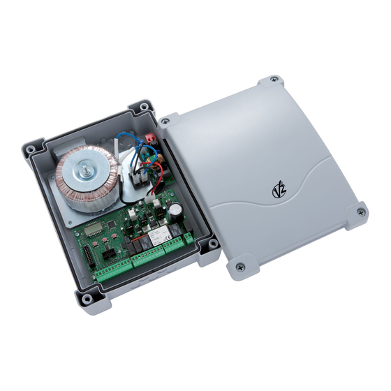
DESCRIPTION OF THE CONTROL UNIT hose clamp to fix dangerous voltage wires near the terminal The digital control unit CITY2+ is an innovative V2 product that board and another hose clamp to fix safety low voltage wires guarantees a safe and reliable automation of leaf swing or used for accessories connection;... -
Page 3: Installation
INSTALLATION PHOTOCELLS Installation of control unit and safety devices must be carried out The control unit considers two kinds of photocells, depending on with power disconnected. the terminal to which they are connected: • Photocell 1: that is to say, photocells installed on the gate POWER SUPPLY inner side, which are active both during the opening and the closing phase. -
Page 4: Safety Ribbons
SAFETY RIBBONS LIMIT SWITCH AND ENCODER The control unit considers two kinds of safety ribbons, The CITY2+ controller can control the gate's travel using a limit depending on the terminal to which they are connected: switch and/or an encoder. • Type 1 (fixed): they are mounted on walls or on other fixed CAUTION: The use of these devices is strongly obstacles that are approached by the gate doors during the recommended to ensure that the gate opens and closes... -
Page 5: Stop
GATES WITH SINGLE PANELS • Timer mode: it is similar to the standard mode but the gate Installation of limit switch stays open (completely or partially) while the contact is • Connect the open limit switch to terminals K1 and K5 closed on input;... -
Page 6: External Aerial
The ADI (Additional Devices Interface) interface of the control unit CITY2+ allows the connection to V2 optional modules. Common (-) Refer to V2 catalogue or to the technical sheets to see which Photocells type 1. N.C. contact optional modules with ADI interface are available for this control Photocells type 2. -
Page 8: Control Panel
CONTROL PANEL USE OF THE DOWN, MENU AND When power is on, the control unit checks that display correctly UP KEYS FOR PROGRAMMING operates by switching on all segments for 1.5 sec. 8.8.8.8. Programming of the functions and times of the controller is Firmware version, e.g. -
Page 9: Self-Learning Of Working Times
LOADING OF DEFAULT 4. Press the MENU key to start the self-learning cycle for the work cycle times: PARAMETERS CAUTION: This procedure varies based on the number of gate If necessary, it is possible to restore all the parameters to their panels and travel control devices installed. -
Page 10: Obstacle Sensor Operation
OBSTACLE SENSOR OPERATION Time menu setup Time menus allow setting a function duration. When you enter CITY2+ control unit is equipped with a sophisticated system that into a time menu, the current setup value will be viewed; the allows detecting if there is any obstacle stopping the gate display mode depends on the current value: motion. - Page 11 Leaf 1 opening time Motor 1 will be operated for the setup time in the opening phase; in case there is an obstacle or the end of stroke operates, the control unit can stop the opening phase before the relevant time expires. Leaf 2 opening time Motor 2 will be operated for the setup time in the opening phase;...
- Page 12 Partial closing time (pedestrian access) When the control unit receives a Start Pedestrian command, it will use this time to close the gate. Max allowed time to be setup is 1 minute. To avoid that the door does not close completely, we recommend to setup a longer time than t.APP opening time.
- Page 13 Silent Locking Mode This menu allows you to select the silent operation mode for the electric lock. Silent Mode (100 Hz) Standard Mode (50 Hz) CAUTION: In silent mode, the voltage supplied to the lock has a higher frequency in order to make the locking less noisy. In some cases, there may be problems when unlocking.
- Page 14 Motor 2 power This menu allows adjusting the motor 2 power. The displayed value is the percentage of max. motor power. Power Motor 1 during slow-down phase This menu allows you to regulate the power of motor 1 during the slow-down phase.
- Page 15 Starting ramp In order not to stress too much the motor, when the motion starts the power is gradually increased, until reached the set value or 100% if the take-off is enabled. Higher is the set value, longer the length of time of the ramp, that is the time necessary to reach the value of nominal power.
- Page 16 Start command during the opening phase This menu allows fixing the control unit conduct in case it receives a Start command during the opening phase. PAUS The gate stops and goes to pause. ChiU The gate immediately starts closing. The gate go on with the opening phase (command is ignored). Select option PAUS, to set up the “step-by-step”...
- Page 17 Automatic closing During the automatic operation, the control unit will automatically close the gate when a set-up time expires. The Start command, if enabled by St.PA menu, allows closing the gate before the set up time expires. In semi-automatic operation, that is to say, if the automatic closing function is disabled by setting the value to zero ('no' will be displayed), the gate can be closed through the start command only: in this case, St.PA menu setup will be ignored.
- Page 18 Auxiliary channel This menu allows setting the operating of the relay of the lighting of the courtesy lights by means of a remote control stored on the channel 4 of the receiver. the relay is activated receiving the transmission of the remote control;...
- Page 19 Otherwise, it will stand still and the flashing light will stay onfor 5 sec. The whole test cycle lasts less than one second WARNING: V2 suggests to keep activated the test of the photocells in order to grant a higher safety of the system.
- Page 20 Test enabled for optical safety edges rESi Test enabled for conductive rubber safety edges WARNING: V2 suggests to keep activated the test of the photocells in order to grant a higher safety of the system. End of Stroke Inputs The CITY2+ controller permits the connection of 4 normally closed (NC)
- Page 21 Encoder Input The CITY2+ controller allows connection to encoders that provide the controller with the position of the gate panels The encoder inputs are enabled The encoder inputs are disabled Anti-skid When an opening or closing operation is interrupted by a command or for the intervention of the photocell, the set-up time for the opposite movement would be excessive, so the control unit operates the motors only for the time necessary to recover the actually covered journey.
-
Page 22: Reading Of Cycle Counter
READING OF CYCLE COUNTER DOWN key, the current counter value will be rounded up or down to thousands, any following pressure will have the setup CITY2+ control unit counts the completed opening cycles of the be increased or decreased of 1000 units. The previous gate and, if requested, it shows that service is required after a displayed count will get lost. -
Page 23: Operation Defects
Change the end of stroke sensor or the broken wiring. disconnecting switch on the power line and remove the If the error persists send the control unit to V2 S.p.A. for repair. power supply terminal. 2. Be sure that there is no voltage break upstream the control Error 5 unit. -
Page 24: City2+ Function Table
CITY2+ FUNCTION TABLE MEMO DISPLAY DATA DESCRIPTION DEFAULT DATA t.AP1 0.0’’ ÷ 5’.00 Open time gate panel 1 22.5’’ t.AP2 0.0" ÷ 5’.00 Open time gate panel 2 22.5’’ t.APP 0.0" ÷ 1’.00 Open time pedestrian gate 6.0’’ t.Ch1 0.0" ÷ 2’.00 Close time gate panel 1 23.5’’... - Page 25 CITY2+ FUNCTION TABLE MEMO DISPLAY DATA DESCRIPTION DEFAULT DATA LUCi Courtesy lights CiCL t.LUC - Timed operation (from 0 to 20 min) - Function disabled CiCL - On for the entire cycle duration Auxiliary channel - Timed operation (from 0 to 20 s) biSt - Bistable operation - Monostable operation...
- Page 27 INDEX CONSEILS IMPORTANTS ............... .54 DÉCLARATION DE CONFORMITÉ...
Need help?
Do you have a question about the CITY2+ and is the answer not in the manual?
Questions and answers