Advertisement
Table of Contents
- 1 Important Remarks
- 2 Declaration of Conformity
- 3 Technical Specifications
- 4 Installation
- 5 Courtesy Light
- 6 Limit Switch Inputs
- 7 External Antenna
- 8 Electrical Connection
- 9 Cable Gland Assembly
- 10 Programming the Operational Logic
- 11 Adjustment of the Power and Operational Times
- 12 CONTROL UNIT INDICATORS (Leds)
- Download this manual
Value moves the world
FLEXY2
CENTRALE DI COMANDO ANALOGICA PER CANCELLI
I
A BATTENTE E SCORREVOLI
ANALOGUE CONTROL UNIT FOR LEAF SWING AND
GB
SLIDING GATES
ARMOIRE DE COMMANDE ANALOGIQUE POUR
F
PORTAILS BATTANTS ET COULISSANTS
CUADRO DE MANIOBRA ANALÓGICO PARA CANCELAS
E
BATIENTES Y CORREDERAS
QUADRO ANALÓGICO PARA PORTÕES DE BATENTE
P
E PORTÕES DE CORRER
ANALOGSTEUERUNG FÜR FLÜGELTORE
D
UND SCHIEBETORE
ANALOGE BESTURINGSEENHEID VOOR DRAAIHEKKEN
NL
EN SCHUIFHEKKEN
PROGRAMATOR ANALOGOWY DO BRAM SKRZYDŁOWYCH I
PL
PRZESUWNYCH
IL 384
EDIZ. 20/03/2014
Advertisement
Table of Contents

Related Manuals for V2 FLEXY2


Summary of Contents for V2 FLEXY2
- Page 1 Value moves the world IL 384 EDIZ. 20/03/2014 FLEXY2 CENTRALE DI COMANDO ANALOGICA PER CANCELLI A BATTENTE E SCORREVOLI ANALOGUE CONTROL UNIT FOR LEAF SWING AND SLIDING GATES ARMOIRE DE COMMANDE ANALOGIQUE POUR PORTAILS BATTANTS ET COULISSANTS CUADRO DE MANIOBRA ANALÓGICO PARA CANCELAS BATIENTES Y CORREDERAS QUADRO ANALÓGICO PARA PORTÕES DE BATENTE...
-
Page 2: Important Remarks
• 2004/108/CEE (EMC Directive in accordance with standards EN 61000-6-2, EN 61000-6-3 + EN 50336) V2 has the right to modify the product without previous notice; it also declines any responsibility to damage or • 2006/95/CEE (Low Voltage Directive in accordance with injury to people or things caused by improper use or wrong standards EN 60335-1 + EN 60335-2-103) installation. -
Page 3: Installation
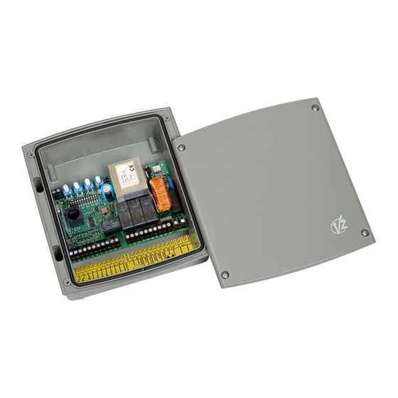
DESCRIPTION OF THE CONTROL UNIT PHOTOCELLS The FLEXY2 control unit is an innovative V2 product guaranteeing The control unit has a 24VAC power supply for photocells with safety and reliability for swing gate automation. switch normally closed, and can perform an operational test The FLEXY2 design has been aimed at creating a product which before to starting the gate opening procedure. adapts to suit all needs, thus obtaining an extremely versatile control unit satisfying all the necessary requirements for a The photocell can be used with two settings: functional and efficient installation. 1. Photocell always active: • 230V - 50Hz or 120V - 60Hz power supplies, depending on the Intervention of the photocell during opening or closing causes model, for 2 single phase motors (700W global). the gate to stop. When the photocell restores, the gate re- opens completely. • Input for keyswitch or push-button. 2. Photocell NOT active during opening: • Input for safety photocell. Intervention of the photocell during opening is ignored. Intervention of the photocell during closing causes the gate to • Input for safety edge, capable of handling standard edges re-open completely. -
Page 4: Courtesy Light
COURTESY LIGHT STOP This output has a normally-open clean contact relay which closes The STOP input is intended for devices with the switch normally for approx. 1 second at the start of an opening phase. closed. This switch may be used to activate a courtesy light timer (max. The STOP command causes the immediate stop of the gate. load: 230V - 4 A). A subsequent START command activates the gate in the opposite direction of movement. The switch is on terminals K1 and K2. If the STOP command is given during opening or pause, then there will be no subsequent automatic re-closure. Connect the stop input control device cables between terminals L3 and L8 on the control unit. BLINKER The control unit provides for the use of a 230V - 40W or 120V - 40W blinker with built-in intermittence. LIMIT SWITCH INPUTS Connect the cables to terminals K9 and K10. The control unit is configured for connecting a switch with switch normally closed, which is opened when the gate reaches the desired position. -
Page 5: Electrical Connection
ELECTRICAL CONNECTION A1 A2 POWER WORK PAUSE DELAY mains 1 2 3 4 5 6 7 8 9 10 11 12 PROG.RX RJ45 overload START START P. STOP EDGE PHOTO L9 L10 L11 K1 K2 K3 K4 K5 K6 K7 K8 K9 K10 mains PLEASE NOTE: If not used, the normally closed inputs (STOP, PHOTO, EDGE, FCA, FCC) must be jumpered with the commands common line COM (-) -
Page 6: Cable Gland Assembly
CABLE GLAND ASSEMBLY Antenna The casing can accept 4 cable glands in the special easy-break housings. Antenna shield The type of cable gland is indicated in the figure. Opening command for a standard connection device with switch normally open. PLEASE NOTE: Pedestrian opening command for a standard • Remove the electronic circuit board before drill the casing. connection device with switch normally open. • Drill the container using a suitably sized cutter, according to the STOP command. N.C. switch dimensions of the cable gland. Photocell. N.C. switch • Fix the cable glands using the special nuts. Edge. Switch N.C. or resistive rubber edge Limit switch open. N.C. switch Limit switch closed. N.C. switch Commands common (-) line L9 - L10 24 VAC power output for photocells and other accessories L10 - L11 Power supply for functional test TX photocell K1 - K2 Courtesy light timer activation switch Motor 1 open Motor 1 common... -
Page 7: Programming The Operational Logic
PROGRAMMING THE OPERATIONAL LOGIC It is possible for the control unit to use several different operational logic states, by simply moving the dip-switches located on the card. The functions associated with each individual dip-switch are listed below. FUNCTION SETTING DESCRIPTION Disabled The blinker is switched on when the motors are started Pre-flashing Enabled The blinker is switched on for 2 seconds before the motors are started Enabled The gate is closed automatically after the period of time set by the PAUSE trimmer Automatic closure Disabled On completion of the opening step, the gate remains open. It is necessary to instruct closure with another START command Not accepted Any START command issued during opening is ignored Start during opening Accepted Any START command issued during opening is accepted Inversion Start during opening causes closure. Start during closure causes opening. Operational logic Step Commands subsequent to starting cause, in order: open stop close stop... Enabled At the end of each opening and closing step, the motors slow down in order Slow down to avoid noisy closure and bouncing. -
Page 8: Adjustment Of The Power And Operational Times
ADJUSTMENT OF THE POWER AND OPERATIONAL TIMES POWER: motor power. The power and operating times may be adjusted by means of 4 trimmers located on the control unit: WORK: motor operating time J1 closed = 2 - 50 seconds PLEASE NOTE: it is recommended that operating times J1 opened = 2 - 120 seconds be set with the slow down function disabled (DIP 5 OFF). PAUSE: pause time before automatic re-closure (2 - 150 seconds). - Page 9 STORING OF THE TRANSMITTERS • Keep PROG.RX pressed until the led L1 lightens • Choose the channel you want to memorize and within 5 seconds press and hold the push-button of the transmitter. • Release the push-button, the led switches off and it sends out • The led L1 switches off and it switches on again: this means a sequence of single flashings for 5 seconds: the number of short flashings shows the selected channel that the code has been memorized. • To select the further channels press and release the PROG.RX • The device will wait for a further code to memorize for a maximum time of 5 seconds. push-button within 5 seconds, the led changes type of flashing according to the following table: SELECTED FUNCTION N° Impulses Flashing CHANNEL PROG.RX single double triple quadruple • CHANNEL 1 START • •...
Need help?
Do you have a question about the FLEXY2 and is the answer not in the manual?
Questions and answers