Table of Contents
Advertisement
Advertisement
Table of Contents

Related Manuals for FULTON Vantage VTG Series


Summary of Contents for FULTON Vantage VTG Series
-
Page 1: Operation Manual
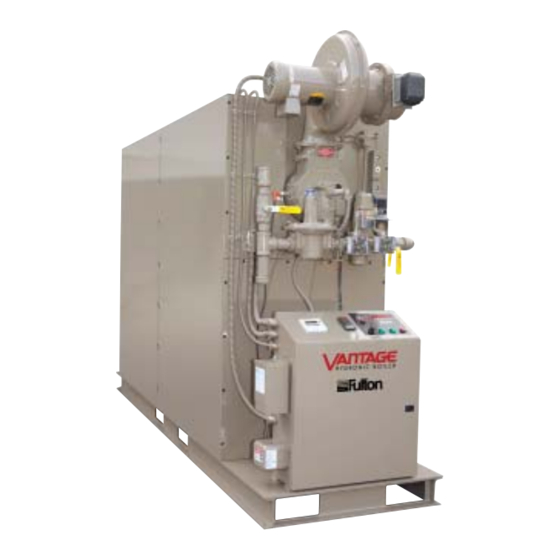
INSTALLATION AND OPERATION MANUAL Vantage (VTG) Condensing Hydronic Boilers Standard, Dual Fuel, and Low Emissions Models 2,000,000 - 6,000,000 BTU/HR 504k - 1.5 MM kCal/HR Serial/ National Board Number Model Fulton Order Sold To Job Name Date VTG-IOM-2013-0815... -
Page 3: Table Of Contents
SYSTEM DESIGN AND BOILER OPERATION .................3-3 Troubleshooting ....................4-8 Siemens LMV36 and LMV37 Control ..............3-4 OPERATING POINTS ON THE SIEMENS LMV CONTROL ...............3-4 NORMAL OPERATION ........................3-4 INITIAL PROGRAMMING ......................3-4 Questions? Call (315) 298-5121, or visit us online at www.fulton.com... - Page 4 TABLE OF CONTENTS VTG-IOM-2013-0815 Warranty & Parts Standard Warranty for Fulton Vantage Hydronic Boilers ........Parts ........................5-5 STANDARD - MAXON BURNER ....................5-6 DUAL FUEL - RIELLO BURNER .....................5-9 LOW EMISSIONS - BEKAERT BURNER ..................5-13 ANNUAL MAINTENANCE KITS ....................5-17 SPARE PARTS KITS ........................5-20...
-
Page 5: Introduction
INTRODUCTION INTRODUCTION INSTALLATION OPERATION MAINTENANCE WARRANTY & PARTS Questions? Call (315) 298-5121, or visit us online at www.fulton.com... -
Page 6: Overview
Code ANSI Z223.1/NFPA 54 latest edition, and the specifi c should it replace existing codes or standards which may be instructions in this manual. Authorities having jurisdiction applicable. Fulton reserves the right to change any part of should be consulted prior to installation. this installation, operation and maintenance manual. -
Page 7: Installation
INSTALLATION INTRODUCTION INSTALLATION OPERATION MAINTENANCE WARRANTY & PARTS Questions? Call (315) 298-5121, or visit us online at www.fulton.com... -
Page 8: Product Overview
The Fulton Vantage hot water boiler is an automatic, fuel-fi red, ultra high- jurisdictional/professional codes and effi ciency boiler. The boiler can either be of the sealed combustion/direct vent regulations. -
Page 9: Placement & Rigging
Proper placement of your Fulton product is essential. Attention paid to regulations. the following points will save a great deal of diffi culty in the future. Correct placement is the fi rst step to trouble-free installation, operation, and maintenance. -
Page 10: Clearances And Serviceability
1. All local and national codes (NFPA, ANSI, UL, CSA, be maintained (Figure 1). This will allow access around ASME) must be followed for proper clearances and the equipment to facilitate maintenance and a safe © The Fulton Companies 2013... - Page 11 HOT WATER OUTLET SIDE VIEW COMBUSTION AIR INLET COLD WATER INLET EXHAUST OUTLET CONDENSATE DRAIN FIGURE 1 - VIEWS OF VANTAGE HYDRONIC BOILER (STANDARD, LOW EMISSIONS AND DUAL FUEL MODELS) Questions? Call (315) 298-5121, or visit us online at www.fulton.com...
-
Page 12: Install Boiler Trim
Clearance from hot water pipes to combustibles must be at least 6 inches (152 mm). © The Fulton Companies 2013... - Page 13 The hydronic system is completely fl ushed prior to installing the boiler itself. Questions? Call (315) 298-5121, or visit us online at www.fulton.com...
- Page 14 Note: Sample piping layout (P&ID) is a general representation of system installation. Good practice should be used in system design, including but not limited to adequate pipe/valve sizing and natural fl ow path for system water. © The Fulton Companies 2013...
-
Page 15: Meet Water Chemistry Requirements
Prevent Oxygen Contamination There are several ways to prevent boiler water oxygen contamination: Minimize system leaks to minimize make up water requirement Questions? Call (315) 298-5121, or visit us online at www.fulton.com... -
Page 16: Eliminate System Air
Test with compressed air or inert vent) is required. gas if possible. 2. To prevent scale corrosion in boiler and associated 4. The boiler must be disconnected at the boiler manual 2-10 © The Fulton Companies 2013... - Page 17 16. Vantage models featuring the Bekaert or Riello burners have pilot assemblies. For Riello burner confi gurations, if vent limiters are not allowed per the AHJ, the pilot regulator will need to be vented accordingly. Bekaert 2-11 Questions? Call (315) 298-5121, or visit us online at www.fulton.com...
- Page 18 For multiple boiler installation, maintain and minimum pipe size of 1 inch (25.4 mm) for the header piping. The maximum number of units to attach per condensate drain kit is 12mm BTU total. Detail A 2-12 © The Fulton Companies 2013...
-
Page 19: Components Requiring Ventilation To The Outdoors
Follow the recommendations of the manufacturer of the ventilation and uncontaminated air for proper gas pressure regulator for specifi c instructions. General FIGURE 6 - FULTON PH NEUTRALIZING KIT (WITHOUT PUMP) 2-13 Questions? Call (315) 298-5121, or visit us online at www.fulton.com... -
Page 20: Install Condensate Drain
Install Condensate Drain iron pipe, PVC or CPVC are not acceptable. A condensate drain kit is intended for use with the Fulton 6. Connect 1 inch (25.4 mm) condensate drain(s) (at the Vantage boiler. The Condensate Drain is Fulton Model Part rear of the boiler), to the 1 inch (25.4 mm) inlet at the... -
Page 21: Install Ph Neutralization Kit
DO NOT USE GASOLINE, CRANKCASE OIL OR ANY OIL CONTAINING The pH Neutralization Kit is a Fulton-provided kit designed to bring the pH level GASOLINE. If in doubt, contact of the boiler’s condensate to a neutral level. It is not a replacement or alternative your Fulton representative prior to for the Condensate Drain Trap. - Page 22 Maximum Fuel Oil 140 F (60 C) Temperature Maximum Suction and Return 29 PSI (199.9 kPa) Pressure Pressure Calibration at the 198-200 PSI (1365 - 1379 kPa) Factory Filter Mesh Width 0.006 Inches (0.15 mm) 2-16 © The Fulton Companies 2013...
- Page 23 5/8” RLS-100-130E (for use with VTG-2000 to VTG-4000) L(ft) O (inch) (ft) +6.6 3/8” 1/2” 5/8” +4.8 +3.3 +1.6 +6.6 +3.3 -1.6 +1.6 -3.3 -4.8 -1.6 -6.6 -3.3 -6.6 2-17 Questions? Call (315) 298-5121, or visit us online at www.fulton.com...
-
Page 24: Hydraulic Connections
Priming operation is possible because the pump is already full of fuel when it leaves the factory. 2-18 © The Fulton Companies 2013... - Page 25 Avoid extensive direction changes (fl ue gases being required to turn around) Never direct fl ue stacks in a downward direction. 2-19 Questions? Call (315) 298-5121, or visit us online at www.fulton.com...
- Page 26 Foreign substances, such as combustible volatiles in the combustion system can create hazardous conditions. If foreign substances can enter the air stream, the boiler combustion air inlet must be piped to an outside 2-20 © The Fulton Companies 2013...
-
Page 27: Combustion Air Supply From The Boiler Room
5. Intake PVC piping must be assembled using cement. This will ensure that the intake is air tight and will not allow contaminates from the boiler room into the boiler. The cement must be free fl owing and contain no lumps, 2-21 Questions? Call (315) 298-5121, or visit us online at www.fulton.com... -
Page 28: Exhaust Venting
It is imperative to design such systems to prevent backfl ow of exhaust gases through idle boilers. 2. Vantage boilers cannot be common vented with other equipment. When designing a draft system for a quantity of two or more Vantage boilers, 2-22 © The Fulton Companies 2013... - Page 29 (refer to table 4) at all possible conditions. This includes considering all possible operating conditions of the stack, including: 2-23 Questions? Call (315) 298-5121, or visit us online at www.fulton.com...
- Page 30 AIR INTAKE AND EXHAUST TERMINATION SHOULD BE LOCATE INTAKE WALL PENETRATION SEPARATED AS FAR AS POSSIBLE TO PREVENT FLUE GAS UPWIND OF EXHAUST PIPING RECIRCULATION DURING DIFFERENT WIND CONDITIONS AIR INTAKE 48 IN. / 122 CM. WALL PENETRATION 2-24 © The Fulton Companies 2013...
-
Page 31: Venting Terminations
Use adhesive material to seal around the vent on both sides of the wall. When penetrating a combustible wall, a wall thimble must be used. See Figure 13 2-25 Questions? Call (315) 298-5121, or visit us online at www.fulton.com... -
Page 32: Wall Thimble Installation
(on the inside and outside of the wall) through which intake and vent pipes are passed. They will prevent the intake and vent pipes from being pushed or pulled. FIGURE 14 - WALL THIMBLE INSTALLATION 2-26 © The Fulton Companies 2013... -
Page 33: Horizontal Vent Termination
8. To prevent the possible re-circulation of fl ue gases, the vent designer must take into consideration such things as prevailing winds, eddy zones, building confi gurations, etc. Fulton cannot be held responsible for the eff ects such adverse conditions may have on the operation of the boilers. -
Page 34: Electrical Connections
Adhere to the following for multi-skid engineered systems: common vent system should be resized to approach the minimum size as determined using the appropriate 1. Refer to the Fulton mechanical/electrical drawings tables. during assembly. 2. Ensure that equipment orientation allows for operation Electrical Connections interface and maintenance. - Page 35 11. Pneumatically test the piping (at 15 psig [103 kPa]maximum) prior to fi lling the systems. 12. Check bolts and connections for tightness after the fi rst heat up cycle. Retorquing may be required. 2-29 Questions? Call (315) 298-5121, or visit us online at www.fulton.com...
- Page 36 INSTALLATION SECTION 2 VTG-IOM-2013-0815 2-30 © The Fulton Companies 2013...
-
Page 37: Operation
OPERATION INTRODUCTION INSTALLATION OPERATION MAINTENANCE WARRANTY & PARTS Questions? Call (315) 298-5121, or visit us online at www.fulton.com... -
Page 38: Perform Pre-Start-Up Inspection
When all air has escaped and only water is impacted part of the control system. discharged, close the zone valve. When all zones have been purged (one at a time), close the vent on the combination shutoff /purge valve. © The Fulton Companies 2013... -
Page 39: Commission The Boiler
System Design and Boiler Operation gas control(s) which have been under water. The Vantage boiler must be installed in an appropriately designed system per Questions? Call (315) 298-5121, or visit us online at www.fulton.com... -
Page 40: Siemens Lmv36 And Lmv37 Control
Every Vantage boiler comes with a Test Fire Report from the factory. This includes nine operating points that are set up in the Siemens LMV control by Fulton’s Commissioning/Start up by a non- technicians. Parameter 545 needs to be set up specifi c to job site operating... -
Page 41: Commissioning The Unit
8. To make changes: Drive the unit to the high-fi re position, P9. Check the O2 level in the stack. Questions? Call (315) 298-5121, or visit us online at www.fulton.com... -
Page 42: Siemens Lmv51 Control
Every Vantage boiler comes with a Test Fire Report from the factory. This includes from the component manufacturer. nine operating points that are set up in the Siemens LMV control by Fulton’s technicians. Point #1 needs to be set up specifi c to job site operating conditions... -
Page 43: Setting Pilot (For Boilers Equipped With A Pilot)
1. Following the Pre-Ignition phase (see previous section), the unit will purge then drive to the ignition position and ignite. The burner control will stay at this pilot hold stage so you can inspect and adjust the pilot as needed. Questions? Call (315) 298-5121, or visit us online at www.fulton.com... -
Page 44: Setting Main Burner Ignition
Setting Main Burner Ignition 1. Under Params&Display > RatioControl > ProgramStop, change the Non-Fulton product information is for ProgramStop to 52 Interv2. This is the main burner ignition position. Press reference purposes only. No Fulton Enter and confi rm that 52 Interv2 is acknowledged in the current fi eld. This... -
Page 45: Setting Modulation
3. Press Enter once. Select ChangePoint by pressing the arrow keys to highlight and then press Enter to select. This will cause the servo motors to move to this low fi re point. Questions? Call (315) 298-5121, or visit us online at www.fulton.com... -
Page 46: Setting The Complete Turndown Range
Low fi re is now set and stored. jurisdictional/professional codes and regulations. Setting the Complete Turndown Range Non-Fulton product information is for NOTE: It is only necessary to approximate the setting through the reference purposes only. -
Page 47: Operating Temperatures And Fuel Selection
32A, and the Siemens RWF40. SC-500 Temperature Controller Basic Programming CHANGE SET POINT 1. Set Point Mode is accessed through the switch selection or BMS screen selection. 3-11 Questions? Call (315) 298-5121, or visit us online at www.fulton.com... -
Page 48: Yokogawa Ut 32A Basic Programming
SET BOILER ON TEMPERATURE regulations. 1. From Main Menu screen, select System Confi g. Non-Fulton product information is for reference purposes only. No Fulton 2. Select Sensor Confi g and set. document may substitute for full review of documentation available ... -
Page 49: Siemens Rwf40 Basic Programming
I.e. SP1 – HYS.1 = Heater On Temperature. Ex. SP1 = 160, HYS.1 = 5 3-13 Questions? Call (315) 298-5121, or visit us online at www.fulton.com... -
Page 50: Access To Variable Speed Drive Blower Motor
(Models VTG-3000LE, VTG-4000LE) NOTE: Some Fulton Vantage Low Emissions Designs include a Variable Frequency Drive (VFD). The VFD is a Telemechanique Altivar 21 style. The Variable Speed Drive programs are password protected and should only be accessed by factory-trained personnel. Please contact your authorized Fulton representative for assistance. -
Page 51: Test Of Ignition Safety System
Turn the boiler on. Water temperature will rise until the boiler locks out. This condition has to be manually reset. 2. Alter the high limit cut off temperature to normal level, typically 10-20 degrees above set point. 3-15 Questions? Call (315) 298-5121, or visit us online at www.fulton.com... -
Page 52: Perform Test Of Low Gas Pressure Switch
Vantage boilers should be operated and controlled so the boiler cycles less than 12,000 times per year. Vantage boilers should be operated and controlled so that the temperature diff erential across the boiler does not exceed 100°F (38°C). 3-16 © The Fulton Companies 2013... -
Page 53: Maintenance
MAINTENANCE INTRODUCTION INSTALLATION OPERATION MAINTENANCE WARRANTY & PARTS Questions? Call (315) 298-5121, or visit us online at www.fulton.com... -
Page 54: General
Daily, Weekly and Monthly Maintenance and Inspection (Fulton considers the regulations. following to be good practice for any boiler, and is applicable to the full line of Vantage boilers). It is also good practice for any boiler installation to perform... -
Page 55: Procedure For Cleaning The Air Inlet Filter (Low Emissions Burners)
Exposure to crystalline silica may pose signifi cant health hazards, on the tubes. Consult Fulton Heating Solutions immediately if there is a including but not limited to eye and concern. -
Page 56: Annual Removal And Inspection Of Le Bekaert Burner
Appropriate training and instructions 2. Shut off gas supply. are available from the Fulton Service Department at (315) 298-5121 or 3. Disconnect the gas union and properly support the gas train. It may be your local Fulton Heating Solutions possible to remove just the gas actuator from the valve body to gain access Representative. - Page 57 1-13/16” socket and ¾ x ½” adapter (U.S. only; these were provided from the factory and should be stored in a safe place in the boiler room). If these components have been misplaced, Questions? Call (315) 298-5121, or visit us online at www.fulton.com...
- Page 58 SECTION 4 VTG-IOM-2013-0815 WARNING please contact Fulton to purchase replacement components. The VTG-2000 through VTG-5000 Fulton part numbers are All information in this manual is for 2-22-000570 (socket) and 2-22-000571 (adapter). For VTG-6000, reference and guidance purposes, the socket part number is is 2-22-000572. It is a 1 ”...
-
Page 59: Inspecting/Cleaning The Flue Passages
Also note the location of lbs (31.2 NM) on all bolts. Do not replace any bolts, nuts, the jumper on the left side of the motor. washers or other components without consulting the Questions? Call (315) 298-5121, or visit us online at www.fulton.com... -
Page 60: Ignition Pilot Adjustment - Dual Fuel Burners
The screen will then display ‘Actuator Address Assignment Successful’ . » Press Escape until the main menu is reached. Under OperationalStat > Status/Reset, reset the fault. 17. The boiler emissions may not be correct after changing © The Fulton Companies 2013... - Page 61 FIGURE 17 - RLS-100-130E BURNER ELECTRODE POSITION FOR GAS OPERATION OPERATION Electrode Ignition Pilot FIGURE 18 - RLS-160 BURNER ELECTRODE AND IGNITION PILOT FIGURE 20 - RLS-160 BURNER ELECTRODE POSITION FOR OIL LOCATIONS OPERATION Questions? Call (315) 298-5121, or visit us online at www.fulton.com...
- Page 62 Air in pilot gas line Have the boiler attempt to light up to three times. If the boiler fails to light, call Fulton. Ignitor failure 1. Check the gap between the top of the electrode and the pilot tube wall. The gap should be 1/16”...
- Page 63 4-11 Questions? Call (315) 298-5121, or visit us online at www.fulton.com...
- Page 64 If UV scanner/fl ame rod does not detect the fl ame Iden fy and correct. during the 4-second trial-for-igni on period, the gas valve and spark igni on are de-energized. At this me a safety lockout occurs. 4-12 © The Fulton Companies 2013...
-
Page 65: Warranty & Parts
WARRANTY & PARTS INTRODUCTION INSTALLATION OPERATION MAINTENANCE WARRANTY & PARTS Questions? Call (315) 298-5121, or visit us online at www.fulton.com... - Page 66 WARRANTY & PARTS SECTION 5 VTG-IOM-2013-0815 © The Fulton Companies 2013...
-
Page 67: Standard Warranty For Fulton Vantage Hydronic Boilers
Fulton will repair or replace any part of the Vantage boiler found to be defective in workmanship or material within 18 months of shipment from the factory or 12 months from start up (whichever comes fi rst). Fulton shall be notifi ed in writing as soon as any defect becomes apparent. Defective parts must be returned to Fulton for evaluation and warranty consideration. - Page 68 PAGE INTENTIONALLY LEFT BLANK...
-
Page 69: Parts
Fulton Companies. When ordering replacement parts, please have recommended for this equipment. the model number and serial number of your Fulton boiler ready. Factory-direct Use of non-factory authorized parts may jeopardize safety and system... -
Page 70: Standard - Maxon Burner
1-1/2” BALL VALVE, #80-107-01 2-30-000510 1-1/2” ECLIPSE BUTTERFLY VALVE 1-1/2” ECLIPSE BUTTERFLY VALVE ASSEMBLY W/SQM33 2-40-001080 SERVO 2-30-000516 1-1/2” REGULATOR (1 PSI MAX) RV81 2-30-000003 1-1/2” SINGLE SHUTOFF VALVE, #VGG10.404U © The Fulton Companies 2013... - Page 71 3RT1015-1AK6 MOTOR CONTACTOR 7 AMP 120V 2-40-000567 3RT1016-1AK6 MOTOR CONTACTOR 9 AMP 120V 2-40-000801 4 X 12 TYPE J THERMOCOUPLE #92-006-04-20 2-40-000082 6 KV 120V/60HZ GAS IGNITION TRANSFORMER #A06-SC2 Questions? Call (315) 298-5121, or visit us online at www.fulton.com...
- Page 72 2-45-000040 1/2” KNOCKOUT PLUGS #2643 2-12-000210 1/4” ROPE GASKET (PER FT) 2-22-000035 12-14 X 3/4” SELF-TAPPING HEX HEAD SCREWS 2-12-000416 4” 150# ELASTAGRAPH RING GASKET 1/8THK SS304 © The Fulton Companies 2013...
-
Page 73: Dual Fuel - Riello Burner
2-30-001619 AIR PRESSURE SWITCH #3012948 2-30-001640 BURNER/BLOWER ASSEMBLY RLS 100E VTG-2000DF 2-30-001612 BURNER/BLOWER ASSEMBLY RLS 130E VTG-3000DF 2-30-001612 BURNER/BLOWER ASSEMBLY RLS 130E VTG-4000DF Questions? Call (315) 298-5121, or visit us online at www.fulton.com... - Page 74 1” VENT VALVE ASSEMBLY (DBB), #8215C53 2-30-000281 1-1/2” BALL VALVE, #80-107-01 2-30-000516 1-1/2” REGULATOR (1 PSI MAX) RV81 2-30-000003 1-1/2” SINGLE SHUTOFF VALVE, #VGG10.404U 2-30-000220 1/4” UL BALL VALVE, #80-101-01 5-10 © The Fulton Companies 2013...
- Page 75 AZL DISPLAY MODULE #AZL52.40B1 2-40-000430 CABLE FOR AZL DISPLAY #AGG5.635 2-40-000447 CAN BUS WIRE (PER FT) #AGG5.643 2-40-000429 LMV CONNECTOR PLUG SET #AGG5.720 5-11 Questions? Call (315) 298-5121, or visit us online at www.fulton.com...
- Page 76 2-23-000295 6 OZ. TOUCHUP SPRAY PAINT - SMOKY ASH 2-45-000053 7/8” KNOCKOUT PLUGS #2703 4-57-000440 CONDENSATE DRAIN KIT ASSEMBLY 2-10-000168 FLOAT ASSEMBLY FOR CONDENSATE DRAIN KIT 5-12 © The Fulton Companies 2013...
-
Page 77: Low Emissions - Bekaert Burner
BEKAERT MESH BURNER VTG-4000LE #100.238.005-D 2-12-003030 BURNER GASKET SET 5-10-003076 BURNER HOUSING VTG-3000LE 5-10-003476 BURNER HOUSING VTG-4000LE 2-12-000258 BURNER REFRACTORY VTG-3000LE 18-3/4” OD X 10”ID 5-13 Questions? Call (315) 298-5121, or visit us online at www.fulton.com... - Page 78 2-40-000390 #QPH31.050M00 LOW GAS PRESSURE SWITCH W/MR 1-20”WC - 2-40-000387 #QPL31.050M00 2-40-000380 MAIN DOUBLE BODY GAS VALVE, #VGD20.503U PILOT LINE 2-30-000111 1/2” UL BALL VALVE #80-103-01 5-14 © The Fulton Companies 2013...
- Page 79 2-45-000387 7-1/2 AMP TIME DELAY FUSE #ATQR7-1/2 2-45-001000 2 AMP FUSE #ATQR2 - (REPLACES FNQ-R-2) 2-45-000381 3 AMP FUSE #ATQR3 - (REPLACES FNQ-R-3) 5-15 Questions? Call (315) 298-5121, or visit us online at www.fulton.com...
- Page 80 3” WATER LEVEL PROBE SAFETY RELIEF VALVE 2-30-000221 1-1/4” SAFETY VALVE 30 PSI #10-616-05 2-30-000922 1-1/2” SAFETY VALVE 30 PSI #10-617-05 2-30-000266 1-1/4” SAFETY VALVE 60 PSI #10-616-12 5-16 © The Fulton Companies 2013...
-
Page 81: Annual Maintenance Kits
2-30-000807 OIL NOZZLE, 5GPH 60 DEG. #C5222450 2-12-000533 PRIMARY PV MILL BOARD GASKET VTG-2000 2-12-000905 SECONDARY HEAT EXCHANGER DOOR GASKET 14”OD X 12”ID 5-17 Questions? Call (315) 298-5121, or visit us online at www.fulton.com... - Page 82 OIL NOZZLE, 7.5GPH 45 DEG. #C5222438 (2 INCLUDED) 2-20-000023 3” WATER LEVEL PROBE 4-30-003002 VTG-3000 BEKAERT NATURAL GAS PART NO DESCRIPTION 2-12-000049 1” FLAT ROPE GASKET (11FT INCLUDED) 5-18 © The Fulton Companies 2013...
- Page 83 BURNER REFRACTORY RING VTG-4000DF 22-7/8” OD X 10-1/4” ID 2-30-001621 GAS IGNITION ELECTRODE #3013052 2-30-001628 OIL IGNITION ELECTRODES #3013040 & 3013041 (SET OF 2) 5-19 Questions? Call (315) 298-5121, or visit us online at www.fulton.com...
-
Page 84: Spare Parts Kits
RED PUSH BUTTON LIGHT #3SB3001-0BA21 - (2 INCLUDED) 2-40-000472 SERVO MOTOR (FOR LMV 37) #SQM33.550A9 2-40-001083 SQM 33 GAS SERVO COUPLING #CCM10DCA-M10RXA 2-40-001084 SQM 33 AIR SERVO COUPLING W/ SET SCREW 5-20 © The Fulton Companies 2013... - Page 85 DESCRIPTION 2-30-000343 0-400 PSI GAUGE (LIQUID FILLED) #Q817 2-45-000309 BLACK 2 POSITION SWITCH #3SB3202-2KA11 - (2 INCLUDED) 2-40-000648 3RB2016-2PB0 OVERLOAD 1.5-6 AMP W/MR 5-21 Questions? Call (315) 298-5121, or visit us online at www.fulton.com...
- Page 86 3RT1016-1AK6 MOTOR CONTACTOR 9 AMP 120V 2-40-000801 4 X 12 TYPE J THERMOCOUPLE #92-006-04-20 2-40-000096 BASE FOR ICE CUBE RELAY #700HN125 - (3 INCLUDED) 2-10-000168 FLOAT ASSEMBLY FOR CONDENSATE DRAIN KIT 5-22 © The Fulton Companies 2013...
- Page 87 GENERAL PURPOSE (ICE CUBE) RELAY 120V-AB #700HA32A1 - (3 INCLUDED) 4-40-003040 IGNITION WIRE SET ASSEMBLY VTG-4000 2-40-000421 LOW WATER CUT OFF RELAY #26MB1M0-FF 2-45-000305 RED PUSH BUTTON LIGHT #3SB3001-0BA21 - (2 INCLUDED) 5-23 Questions? Call (315) 298-5121, or visit us online at www.fulton.com...
- Page 88 VTG-3000 DF MAXON BURNER, #EB4MRVC 50P EB3 REFRACTORY RING VTG-2000, 17-1/2” OD 2-12-000262 X 12-1/8” ID EB4 REFRACTORY RING VTG-3000, 18-3/4” OD 2-12-000261 X 14-5/16” ID 8” BURNER DISCHARGE SLEEVE GASKET 2-45-000533 #28476 5-24 © The Fulton Companies 2013...
- Page 89 OIL PUMP MOTOR 3/4HP TEFC C-FACE 2-40-001600 #C6T17FK5E 2-30-000780 LOVEJOY COUPLING #68514444829 2-30-000283 OIL SOLENOID VALVE 120/60 #8262G023V PRESSURE SWITCH 15-150PSI AUTO RESET 2-40-003043 KP-36 #060-213166 5-25 Questions? Call (315) 298-5121, or visit us online at www.fulton.com...
- Page 90 LMV CONNECTOR PLUG SET #AGG5.720 TRIM / MISC. 2-23-000172 6 OZ. TOUCHUP TECH TAN SPRAY PAINT CANS X 2-12-000051 3/8” ROPE GASKET (PER FT) 2-12-000003 5/8” ROPE GASKET (PER FT) 5-26 © The Fulton Companies 2013...
- Page 91 WARRANTY & PARTS SECTION 5 VTG-IOM-2013-0815 5-27 Questions? Call (315) 298-5121, or visit us online at www.fulton.com...
- Page 92 WARRANTY & PARTS SECTION 5 VTG-IOM-2013-0815 5-28 © The Fulton Companies 2013...
- Page 93 WARRANTY & PARTS SECTION 5 VTG-IOM-2013-0815 5-29 Questions? Call (315) 298-5121, or visit us online at www.fulton.com...
- Page 94 WARRANTY & PARTS SECTION 5 VTG-IOM-2013-0815 5-30 © The Fulton Companies 2013...
- Page 96 Fulton Companies. Fulton Boiler Works, Inc., Fulton Heating Solutions, Inc. & Fulton Thermal Corporation are part of the Fulton Group of Companies, a global manufacturer of steam, hot water and thermal fl uid heat transfer systems.
Need help?
Do you have a question about the Vantage VTG Series and is the answer not in the manual?
Questions and answers