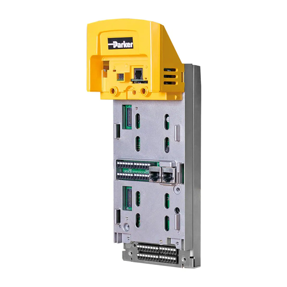
Summary of Contents for Parker LINKnet AC30 Series
Page 1
Product Manual HA474739U001 AC30P, AC30D and the AC30V LINKnet firmware Issue 5.2 version LN 1.7.1 DRV x.17.2 is compatible with DSE version 3.11 or greater.
Page 2
All rights strictly reserved. No part of this document may be stored in a retrieval system, or transmitted in any form or by any means to persons not employed by Parker Hannifin Corporation, Electromechanical and Drives Division without written permission from Parker Hannifin Corporation, Electromechanical and Drives Division.
If the firmware in the drive is Codesys compatible, the drive can be programmed with PDQ (Parker Drive Quicktool) or PDD (Parker Drive Developer). The CoDeSys drive firmware can be changed to LINKnet via DSE (version 3.10 or later) or via a SD card.
Further Reading AC30 Series Drive Product Manual HA501718U002. Product Features • Supports Phase Locking on the AC30P/D Series drive. (LINKnet firmware version LN 1.7 or greater). • Supports 690Like Phase Locking on the AC30D Series drive. (LINKnet firmware version LN 1.7 or greater). •...
Ethernet Recommendations: The PLC should be set up for Point To Point (Unicast) connection instead of Multicast connection. If Multicast is used, a managed switch is recommended / required. The LINKnet module should be in a LAN / VLAN with only other equipment associated with its operation.
LINKnet network. SSD Drives graphic configuration software package Drive System Explorer 890 (DSE890) version 3.07 and all subsequent versions support LINKnet. If you have an older version, updates may be obtained simply by doing a HELP / CHECK FOR UPDATES within DSE or by contacting Parker SSD Drives Product Support...
Getting Started – Updating the Drive Firmware In order to use the AC30 drive with the software DSE (Drive System Explorer or DSELite, the firmware in the drive must be changed from CoDeSys based to LINKnet based. There are several ways to change the drive firmware.
Page 10
For a AC30P or AC30D drive the window will appear as shown. Select the firmware to install and select INSTALL. If you are connected via switch, verify that the IP ADDRESS and the MAC are correct for the drive. 7. If a window appears requesting the ‘Last 3 Mac Octets” go to the GKP of the drive and go to PARAMETERS | BASE COMMS | ETHERNET and scroll until MAC ADDRESS appears.
Updating a LINKnet drive to LINKnet using DSE The drive already has LINKnet firmware installed If the drive already has LINKnet firmware installed and you want to upgrade the firmware to a later revision, use this procedure. Note: If a AC30V drive already has LINKnet firmware v1.6 installed this procedure can’t be used.
Page 12
For a AC30P or D drive, the window will appear as H. Click the INSTALL button. I. If an error message appears in the Scratchpad [ERROR] connect failed : Connection attempt timed out. and the GKP / MMI on the drive is blank or has the hour glass, Immediately click on the INSTALL button again.
Updating the Drive Firmware using a SD card Preparing the SD Card. Copy the AC30 LINKnet firmware to an SD card, make sure the name on the file is named: ‘firmware.30x’ for a AC30V and the file name for a AC30P/D is ‘firmware.30p’ Beware: The existing Codesys configuration in the drive will be lost when updating the drive to the LINKnet firmware.
Getting Started – GKP (Graphical Key pad) Appears when the drive has an active Ethernet connection DSE Configuration Name Drive Current and Voltage Rating LN 1.6 indicates the LINKnet Firmware DRV 1.14 indicates the version AC30 Drive Firmware version LINKnet IP Address. Only appears when the drive has an active Ethernet connection...
Page 15
Getting Started – Connecting to DSE 1. Connect an Ethernet cable to the AC30 drive. The Ethernet port is located on the top left hand side of the drive. 2. Connect this cable to the PC which has DSE installed. 3.
Chapter 3 - Initial Set-up IP addressing information Each LINKnet module must have a unique IP address. Each LINKnet module has a unique default IP shipping address of 192.168.1.xxx. The last 3 digits will be random for each Module in the range of 1 - 127. When the LINKnet module is powered up in a system and it has the default shipping configuration, it will self-assign a unique address on each LINKnet Module as described above, with a subnet Mask of 255.255.254.0 At this point DSE can be launched and all of the LINKnet modules will appear in the Module...
Setting the Node Address Up to 127 LINKnet nodes can be addressed in the LINKnet configuration. Thus, the NODE ADDRESS range is 1 – 127. To set the Node Address go to EDIT / Net Address and set the Node Address. The Node Address in the example shown below is address 10.
Setting the Computer IP Address for AC30 LINKnet Access via Ethernet When communicating to the LINKnet via Ethernet, the computer must be on the same subnet. To change the pc settings: 1. From the START menu, open the Control Panel and select “Network and Sharing Center” or “Network Connections”...
Page 19
4. As shown above the Local Area Connection Properties dialog will appear. Highlight the “Internet Protocol Version 4 (TCP/IPv4)” (“Internet Protocol TCP/IP” in XP), then click on the Properties box and that should bring up the Internet Protocol Dialog that should look something like: 5.
Chapter 4 - Using DSE and AC30 Programming Node Addressing the LINKnet Modules Each LINKnet module must have a unique Node Address assigned to it. The range allowed in DSE is 1 to 127. AC30 Macro Template The AC30 macro is selected from the File/New drop down menu as shown below. This AC30V or AC30P/D v1.6 supports an AC30 drive with firmware version 1.6.x Select the applicable configuration for your drive.
Page 21
LINKnet AC30V Basic Speed Control Template The AC30V macro has some preconfigured inputs and outputs as default. If another tag or parameter is needed, it can be added inside the macro. It is possible to use both the drives’ internal function blocks and the Link function blocks.
Page 22
Modifying Inside the Macro All the drive functions are available through the macro Deleting and/or Moving an Internal Connection The connections inside the macro can be deleted or moved in the same fashion that is used in DSE. If the connection is only being moved from one block to another block it is not necessary to delete the external macro connection.
Page 23
Certain output tags will require an entry for the connection speed. The faster connection speeds require more of the CPU heap usage. If too many fast connections are made, it may be possible to run out of CPU heap and cause an “L-Error” fault. Keep fast connections to a minimum. 3.
Watchdog Circuit It is recommended that a Watchdog Circuit be implemented in each LINKnet configuration to stop the drive if there is a loss of Ethernet communications. Presently if there is a loss of Ethernet communications on the LINKnet drive, it will continue to run and not fault. Within DSE there is a WATCHDOG INPUT function block located in the BLOCK MENU.
Saving of Favorites in the GKP In the GKP (Graphical Key Pad) there is a menu called Favorites. It is where 20 selected parameters can be added for quick access. To Add a Parameter to the Favorites Menu Using the GKP, navigate to the parameter of interest. Press and hold the OK key until the Attributes screen is shown, (hold for about 2s) and press the “Add to Favorites”...
Duplicate Node address If there is a duplicate Node address, meaning that 2 or more nodes have the same Node address, the GKP green Run button will flash and the GKP screen backlight will flash off / on, on the modules that have the duplicate addresses.
AC30 Additional Function Blocks There are additional function blocks which can be used on the AC30P/D and AC30V Series drive. In the DSE menu Block / AC30 these are additional function blocks which can be used: • App Trips. Is used to create a custom Trip for the drive, associated with a custom trip message which will be displayed on the GKP (Graphical Key pad).
AC30P/D Phase blocks There are additional function blocks which can be used on the AC30P/D Series drive for Phase Control.These drives are considere Advanced Performance, thus additional blocks can be used and the blocks are green in color. In the DSE menu Block / AC30 the additional Phase function blocks are: Virtual Master, Virtual Slave, Position Loop, Phase Move, Phase Inch, Phase Tuning, Phase Cam and the Cam Table.
Chapter 5 – Connecting to the Drive To connect to the drive an Ethernet cable is required To use the Ethernet connection the PC must be set up to be on the same subnet address as LINKnet. This setup procedure is listed on page 8 of this manual.
Command / Get Info A Command / Get Info shows the modules IP Address as shown below. It also shows the firmware build (shown 1.6), the remote boot loader firmware (shown B1.1) information and the Events/s. This is the number of vm (virtual machine) functions blocks, executing per second.
Chapter 7 – AB EtherNet /IP Server (slave) Example Allen Bradley ControlLogix 1. Start a new program and select the PLC processor and chassis type that is used in your project. Our example uses a 1756-L55A processor and 1756-A7/B rack. Remain Offline until you are ready to download the program.
Page 32
3. Right click on the Ethernet Interface Module, select New Module. This screen will allow the selection of the Generic Ethernet Module. Generic Ethernet Module Select 4. Input the desired module name and IP address. The Comms format will be DATA Int if 16- bit signed integer, or Data-REAL if 32-bit floating point.
Page 33
6. When completed with the setup of the Generic Ethernet Module it can be downloaded to the PLC. For testing purposes it is not necessary to program Ladder Logic in the PLC. The data can be accessed and monitored via Controller Tags. Controller Tags AC30 Series LINKnet Product Manual HA474739U001...
If possible, do not use a Daisy Chain topology as this type adds propagation delays each time data passes from module to module. Daisy Chain Configuration Not Recommended EDS file If required an Electronic Data Sheet (.eds) is available. It can be downloaded from www.parker.com/ssdusa/software under the Various AC/DC Drives Communication Files menu. AC30 Series LINKnet Product Manual HA474739U001...
Chapter 9 – Programming TS8000 Required Modbus Settings There are some settings / limits that are required for the TS8000 communications. The Maximum Segment (Ethernet packet) size is 232: In the Extended Settings, the Word Ordering, Register Writes and the Frame Register Limits need to be set as shown below: AC30 Series LINKnet Product Manual HA474739U001...
Page 36
For each LINKnet module the General / Ping Holding Register must be set to 511. If set to 0, this disables it. Either setting is acceptable. NOTES: 1. When powering up the TS8000, the outgoing data is only sent once to the remote devices. If the TS8000 powers up first or before the other devices, the TS8000 will send this outgoing data before the other devices have time to power up and they will not receive any of this data.
Example: Configuring a TS8000 to Communicate to a AC30V Step 1: Configuring the Modbus Slave Option using DSE Step 1.1: Inserting a Modbus Slave Function Block Display your configuration page. Click on the “Block” menu at the top of the screen. 1.
Page 38
Step 1.2: Attaching Fieldbus Connectors Seven fieldbus connector types are available: Logic Input Integer Input Value Input Logic Output Integer Output Value Output FB Val to Int Output Input connector: the data is sent from the TS8000 to LINKnet Output connector: the data is sent from LINKnet to the TS8000 The fieldbus connectors must be added before they will appear in the Ethernet function block.
Page 39
Step 1.3: Configuring the Fieldbus Connectors Double-click on the function block to display the dialog below. The fieldbus connectors (inputs and outputs) are assignable in the function block along with their data type to/from the TS8000. “32bit order” is set to “High Word First”. This refers to how 32-bit data types, i.e. SINT32, UINT32 and FLOAT are encoded on Ethernet.
Page 40
Ethernet Data Types Data Type Description Range Bytes Used SINT16 16-bit signed integer -32,768 to 32,767 SINT32 32-bit signed integer -2,147,438,648 to 2,147,483,647 UINT16 16-bit unsigned integer 0 to 65,535 USINT32 32-bit unsigned integer 0 to 4,294,967,295 FLOAT 32-bit IEEE-754 floating-point 1.19209290e-38 to value 3.4028235e+38...
Page 41
Setting up the TS8000 Operator Station using DSI8000 1. Select “Modbus TCP/IP Master” protocol for Ethernet Port. The TS8000 is the Master. Set the Primary IP Address. The Ping Holding Register MUST be set to 511 or 0 which disables it. AC30 Series LINKnet Product Manual HA474739U001...
Page 42
3. In the Extended menu check the ‘Disable Code 5 (Single Bit)”, as shown. 4. Set up the Ethernet as shown AC30 Series LINKnet Product Manual HA474739U001...
Page 43
7. Create the Data Tags for reading and writing variables. Please see the example for pre-defined Data Tags. 8. Create the address tags. They are all pre-defined in the example. Data Item: Always select Holding Registers for both 16-bit and 32-bit data types. DO NOT SELECT “Holding Registers (32-bit)”.
Page 44
read/write registers. Each register is 16bits but two registers are used to read/write 32bit data values via Modbus TCP/IP. Whether one or two registers are used to transmit the data depends on the Input/Output Type selected in the Modbus Slave function block. The Input/Output Modbus function block selected determines the VM data format (Logic, Integer or Value) to be used to convert the VM data to the data being sent/received over Modbus.
Chapter 10 - Using Remote I/O DSE contains function blocks, which allow LINKnet to communicate to SSD Recommended* Remote IO devices such as Analog IO and Digital IO as well as other types of hardware, which use the Modbus UDP protocol. There are function blocks in the Block / Remote IO menu: Read Logics, Write Logics, Read Values and Write Values.
Page 46
The above holds true for the Write Logic blocks also. It does not matter where the Digital Input or Digital Output modules are physically located in the Remote IO rack or what type of cards are installed in between these cards. All we care about is how many Digital Inputs cards there and they count from left to right.
Setting up Internal Watchdog on Wago I/O Coupler, 750-352 By default the internal watchdog on the Wago I/O coupler is set for an internal register that has to be set up using Modbus, and writing a specific value. There is an easier way to set up the watch dog so it will shut off all the outputs if communications are lost.
Page 48
User name is admin, and Password is Wago. Now the following window should appear. By default the Watchdog is disabled and set to standard. Click on the empty circle next to Alternative. The Watchdog timeout value is defaulted to 100, which means 100 x 100ms or 10000 msec or 10 sec. This is the time it will take to shut off the outputs once the communications have been lost to the Wago I/O coupler.
Page 49
If it is desired to let LinkNet know if the Wago I/O coupler has stopped communication, the following block can be programmed into the LinkNet node that is controlling it. The Timed output will go to True if the Wago I/O quits talking for the Set time. In This example, the watchdog timeout is 5000ms or 5 sec.
Chapter 11 – Troubleshooting Refer to the AC30 Series Drive Product Manual HA501718U002 for AC30 drive faults. Duplicate Node Address If there is a duplicate Node address, meaning that 2 or more nodes have the same Node address, the GKP (Graphical Key pad) green Run button will flash and the GKP screen backlight will flash off /on, on the modules that have the duplicate addresses.
Chapter 12 Technical Specifications Performance & – Refer to the AC30 Series Drive Product Manual HA501718U002 for AC30 drive for Technical Specifications. Performance • An AC30P&D LINKnet drive has about 20,380 Nodes available. A Node is a measurement of storage units. •...
Chapter 13 Recommended Auxiliary Products – Remote IO: We recommend the following: Wago Series 750 products: 750-352 Ethernet Fieldbus Coupler 750-600 End Module -Terminator 750-601 Power Supply Module 24 V DC, Fused CS475017U006 Fuse for above. 750-430 Digital Input Module 8 Channel DC 24 V 750-530 Digital Output Module 8 Channel DC 24 V 750-457...
– Appendix A AC30 Firmware Release Notes LINKnet firmware version LN 1.7.1 DRV 2.17.2 for the AC30P/D drive PTP looses lock after 36 hours, affecting Phase Locking applications to lose sync, has been fixed. Updated the motor firmware to the latest version DRV 2.17.2 LINKnet firmware version LN 1.7.1 DRV 1.17.2 for the AC30V Drive Updated the motor firmware to the latest version DRV 1.17.2 LINKnet firmware version LN 1.7.1 for the AC30P/D drive DRV 2.16.2...
Page 54
LINKnet firmware version LN 1.6.2 for the AC30V and the AC30P/D drive. Some of the parameters may not get installed when installing a configuration. This has been fixed LINKnet firmware version LN 1.6.1 for the AC30V drive. Added support so the drive firmware can be installed by using DSE v3.08 (or later), thus the SD card is no longer required to install the drive firmware.
Page 55
AC30 Series LINKnet Product Manual HA474739U001...
Need help?
Do you have a question about the LINKnet AC30 Series and is the answer not in the manual?
Questions and answers