Parker ac890 Reference Manual
Hide thumbs
Also See for ac890:
- Product manual (711 pages) ,
- Product manual (591 pages) ,
- Product manual (608 pages)
Advertisement
Quick Links
A C890 Engineering Reference
H A 4 6 8 4 4 5 U 0 0 3
Product Manual : Frames B, C & D
HA468445U003 Issue 4
Compatible with Software Version 3.1 onwards
2008 Parker SSD Drives, a division of Parker Hannifin Ltd.
All rights strictly reserved. No part of this document may be stored in a retrieval system, or
transmitted in any form or by any means to persons not employed by a Parker SSD Drives
company without written permission from Parker SSD Drives, a division of Parker Hannifin Ltd .
Although every effort has been taken to ensure the accuracy of this document it may be necessary,
without notice, to make amendments or correct omissions. Parker SSD Drives cannot accept
responsibility for damage, injury, or expenses resulting therefrom.
WARRANTY
Parker SSD Drives warrants the goods against defects in design, materials and workmanship for
the period of 24 months from the date of manufacture, or 12 months from the date of delivery
(whichever is the longer period), on the terms detailed in Parker SSD Drives Standard Conditions
of Sale IA500504.
Parker SSD Drives reserves the right to change the content and product specification without
notice.
Advertisement

Related Manuals for Parker ac890


Summary of Contents for Parker ac890
- Page 1 All rights strictly reserved. No part of this document may be stored in a retrieval system, or transmitted in any form or by any means to persons not employed by a Parker SSD Drives company without written permission from Parker SSD Drives, a division of Parker Hannifin Ltd .
- Page 2 UK Head Office: Parker SSD Drives New Courtwick Lane, Littlehampton, West Sussex BN17 7RZ Tel: +44 (0)1903 737000 Fax: +44 (0)1903 737100 CANADA CHINA FRANCE Parker Hannifin Canada Parker Hannifin Motion & Control Parker SSD Parvex Motion and Control Division (Shanghai) Co.
- Page 3 Safety Chapter 1 Safety Please read these important Safety notes before installing and operating this equipment. Caution WARNING CAUTION notes in the manual warn of danger WARNING notes in the manual warn of to equipment. danger to personnel. 890CS Common Bus Supply - Frames B & D; 890CD Common Bus Drive and 890SD Standalone Drive - Frames B, C & D Page...
-
Page 4: Chapter 1 Safety
Safety Requirements IMPORTANT Please read this information BEFORE installing the equipment. Intended Users This manual is to be made available to all persons who are required to install, configure or service equipment described herein, or any other associated operation. The information given is intended to highlight safety issues, and to enable the user to obtain maximum benefit from the equipment. - Page 5 Safety Product Warnings Earth/Ground Caution Caution Protective Conductor Risk of electric shock Refer to documentation Terminal Hazards DANGER! - Ignoring the following may result in injury 1. This equipment can endanger life by exposure to 5. For measurements use only a meter to IEC 61010 (CAT III or rotating machinery and high voltages.
- Page 6 Safety WARNING! - Ignoring the following may result in injury or damage to equipment SAFETY Where there is conflict between EMC and Safety requirements, personnel safety shall always take precedence. • Never perform high voltage resistance checks on the • All control and signal terminals are SELV, i.e. protected wiring without first disconnecting the drive from the by double insulation.
- Page 7 Safety CAUTION! APPLICATION RISK • The specifications, processes and circuitry described herein are for guidance only and may need to be adapted to the user’s specific application. We can not guarantee the suitability of the equipment described in this Manual for individual applications.
- Page 8 Safety Page 890CS Common Bus Supply - Frames B & D; 890CD Common Bus Drive and 890SD Standalone Drive - Frames B, C & D...
-
Page 9: Initial Steps
Getting Started Chapter 2 Getting Started A few things you should do when you first receive the unit. ♦ How the manual is organised ♦ Inspect the unit for transit damage ♦ Initial steps ♦ Packaging and lifting 890CS Common Bus Supply - Frames B & D; 890CD Common Bus Drive and 890SD Standalone Drive - Frames B, C & D Page... -
Page 10: Installation
Getting Started About this Manual IMPORTANT Motors used must be suitable for Inverter duty. Note Do not attempt to control motors whose rated current is less than 25% of the drive rated current. Poor motor control or Autotune problems may occur if you do. This manual is intended for use by the installer, user and programmer of the 890 drive. - Page 11 Getting Started Initial Steps Use the manual to help you plan the following: Installation Know your requirements: • certification requirements, CE/UL/CUL conformance • conformance with local installation requirements • supply and cabling requirements Operation Know your operator: • how is it to be operated, local and/or remote? •...
- Page 12 Getting Started Equipment Inspection ♦ Check for signs of transit damage ♦ Check the product code on the rating label conforms to your requirement. If the unit is not being installed immediately, store the unit in a well-ventilated place away from high temperatures, humidity, dust, or metal particles.
- Page 13 Product Overview Chapter 3 Product Overview C h a p t e r 3 : An introduction to the 890 range of products, and a quick look at the Keypads and available plug- in Options. ♦ Product range ♦ Keypads ♦...
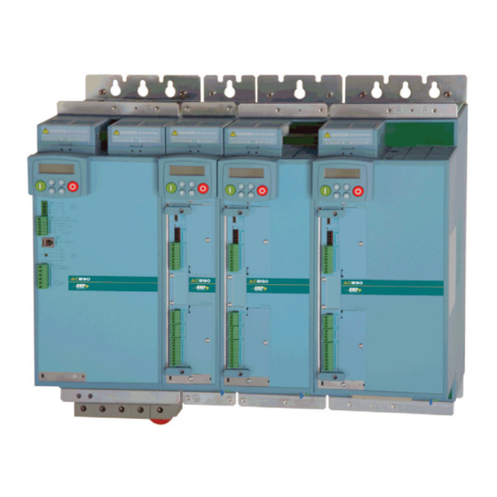
- Page 14 Product Overview Product Range The 890 range is designed to control standard 3-phase ac induction motors and brushless servo motors. There are three main types of 890: 890CS Common Bus Supply 890SD Standalone Drive The Standalone Drive is AC supplied Common Bus Supply connects to AC and provides DC to and provides control for the motor.
- Page 15 Product Overview Note All kW ratings are at 400VAC, all HP ratings are at 460VAC. The units are available in the following frame sizes: 890CS Common Bus Supply FRAME B FRAME D 32A AC (Frame B1) 108A AC (Frame D1) nominal full load input current nominal full load input current 54A AC (Frame B2)
- Page 16 Product Overview 890CS/890CD Selection The required rating for the 890CS input stage can be calculated by adding up the sum of the motor currents attached to the associated output stages. Refer to Appendix E: " Electrical Ratings: : 890CS - Calculation" 890SD Standalone Drive FRAME B FRAME C...
- Page 17 Product Overview Functional Diagrams 890CS Common Bus Supply 890CD Common Bus Drive DC Link Supply BUSBARS BUSBARS KEYPAD KEYPAD OPTION A INTERFACE INTERFACE RS232 FIELDBUS PROGRAMMING HMI REMOTE COMMS PORT INTERFACE +24V AUXILIARY +24V PROGRAMMING mini-USB SUPPLY PORT OPTION F PUMR A POS SPEED PUMR A NEG...
- Page 18 Product Overview 890SD Standalone Drive L1 L2 L3 KEYPAD OPTION A INTERFACE RS232 FIELDBUS PROGRAMMING HMI REMOTE COMMS PORT INTERFACE PROGRAMMING mini-USB PORT Diode OPTION F PUMR A POS Bridge SPEED CONNECTOR PUMR A NEG FEEDBACK (for future use) PUMR B POS INTERFACE PUMR B NEG OPTION B...
- Page 19 Product Overview Keypads The 890 is fitted with the 6511 Keypad. It provides Local control of the 890. For example, you can start and stop the motor and check on diagnostic information. The keypad can also be used to change parameters values on the 890CD and 890SD units. The 6511 keypad fits to the front of the 890.
- Page 20 Product Overview Option Cards The 890CD Common Bus Drive and 890SD Standalone Drive can be fitted with a range of Option Control Cards. They are plugged into the removable Control Board Board. • Feedback Board : Resolver type, Encoder type •...
- Page 21 890CS & 890CD Common Bus Units Chapter 4 890CS & 890CD C h a p t e r 4 : Common Bus Units This chapter describes the mechanical and electrical installation of the Common Bus Units (890CS Common Bus Supply and 890CD Common Bus Drive). It discusses configuring your system, and how to turn the motor for the first time.
- Page 22 890CS & 890CD Common Bus Units Step 1: Mechanical Installation Install the 890 units and associated equipment into the cubicle. The diagram shows a typical layout using Star Point earthing for EMC compliance. Refer to Appendix C for further information. Analog Clean Earth Back plate...
- Page 23 890CS & 890CD Common Bus Units Main Points ♦ These are modular, cubicle-mounted units. They are not suitable for wall-mounting. ♦ Mount the Modules side-by-side vertically on a solid, flat, normally cool, non-flammable, vertical surface. ♦ The 890CS Common Bus Supply is normally mounted to the left of the 890CD Common Bus Drive(s). ♦...
- Page 24 890CS & 890CD Common Bus Units Enclosure/Environmental Information The information here will help you to specify the enclosure to house the 890(s). 890 Operating Conditions Operating Temperature 0°C to 45°C (32°F to 113°F) Product Enclosure Rating IP20 - UL (c-UL) Open Type (North America/Canada) Type 1 Suitable for cubicle mount only Cubicle Installation The 890 must be installed to EN60204 Standard in the cubicle.
- Page 25 890CS & 890CD Common Bus Units 890 Operating Conditions Humidity Maximum 85% relative humidity at 40°C (104°F) non-condensing Atmosphere Non flammable, non corrosive and dust free Climatic Conditions Class 3k3, as defined by EN50178 (1998) Vibration The product has been tested to the following specification: Test Fc of EN60068-2-6 10Hz<=f<=57Hz sinusoidal 0.075mm amplitude 57Hz<=f<=150Hz sinusoidal 1g...
-
Page 26: Operation
890CS & 890CD Common Bus Units Cooling Units are designed for mounting side-by-side as shown. A minimum of 150mm (6") free-air space must be allowed at the top and bottom of each unit. The 890 gives off heat in normal operation. The mounting surface for the unit should be normally cool. Allow a free flow of air through the top and bottom ventilation slots and heatsink. - Page 27 890CS & 890CD Common Bus Units Mounting Dimensions Mount the unit using the keyholes and slots, or fix to a DIN rail (35mm DIN). 72.4 116.2 258.5 The 890CS Common 238.6 Bus Supply is normally 36.2 37.5 mounted to the left of the 890CD Common Bus Drive(s).
- Page 28 890CS & 890CD Common Bus Units Panel Mount Fixings Support the unit at the top and bottom with fixings to secure the unit to the panel. Mark and drill the fixing holes into the panel. Refer to the fixing centres given on the previous page. Insert the fixings into the top hole(s) and hang the unit.
- Page 29 890CS & 890CD Common Bus Units 890 Installation Kit The fitting instructions for the kit are reproduced below. 890CS Common Bus Supply - Frames B & D; 890CD Common Bus Drive and 890SD Standalone Drive - Frames B, C & D Page...
- Page 30 890CS & 890CD Common Bus Units Step 2: Connecting Power In this section we are going to connect the 3-phase supply to the 890CS Common Bus Supply, and connect the 890CD Common Bus Drive(s) via the DC link. We'll also connect the mandatory AC line reactor, the motor, and the (optional) brake resistor. WARNING During commissioning, remove the fuses (or trip the circuit breaker) on your 3-phase supply.
- Page 31 890CS & 890CD Common Bus Units Refer to the 890 Installation Kit for earth/ground fixing details. Fit the appropriate parts. Each unit must be permanently earthed according to EN 50178. For permanent earthing: A cross-section conductor of at least 10mm² is required. This can be achieved either by using a single conductor (PE) or by laying a second conductor though separate terminals (PE2 where provided) and electrically in parallel.
- Page 32 890CS & 890CD Common Bus Units Wiring Diagram 890CS 890CD 890CD X12/01 X14/04 4-12 Page 890CS Common Bus Supply - Frames B & D; 890CD Common Bus Drive and 890SD Standalone Drive - Frames B, C & D...
- Page 33 890CS & 890CD Common Bus Units Key to Wiring Diagram This must be insulated from the back panel. Analog reference X12/01 or digital reference Analog Clean Earth X14/04 must be connected to this busbar, avoiding earth loops. Back-plate Earth the backplate to the star point (G). The 890 must be mounted inside a cubicle complying with the European safety standards Cubicle VDE 0160 (1994)/EN50178 (1998).
- Page 34 890CS & 890CD Common Bus Units Key to Wiring Diagram A very fast external bus (IEEE 1394a) to connect up to 63 units. You will need the FireWire™ Connection FireWire Option Card for each Common Bus Drive, refer to Appendix A. Motor The motor used must be suitable for Inverter duty.
- Page 35 890CS & 890CD Common Bus Units Power Connections - 890CS Common Bus Supply The frame B and frame D 890CS units are each available in two power ratings: Frame B1 : 32A AC rms Input Current Frame D1 : 108A AC rms Input Current Frame B2 : 54A AC rms Input Current Frame D2 : 162A AC rms Input Current See the product rating label on the side of the unit to check the power rating.
- Page 36 890CS & 890CD Common Bus Units Power Connections - 890CS Common Bus Supply DC+ / DC- Bottom Terminals - 890CS Option Use these terminals to wire the DC Bus if not using the SSD_Rail busbar. Use correctly rated wire - refer to Appendix E. Uses include connection to the 890 Common Bus Adaptor unit, or for connection to a 690+ AC Drive for example.
- Page 37 890CS & 890CD Common Bus Units Power Connections - 890CS Common Bus Supply EXTERNAL BRAKE RESISTOR - Option You can connect an external brake resistor between terminals DBR+ and DBR-. DO NOT apply external voltage sources (mains supply or otherwise) to the braking terminals.
- Page 38 890CS & 890CD Common Bus Units Power Connections - 890CD Common Bus Drive Power Connections - 890CD Common Bus Drive EARTH/GROUND Fix the earth from the Motor to the base of the Fix Drive earth connections to drive. Maximum wire sizes: Maximum wire sizes: Frame B: 6mm / 10AWG...
- Page 39 890CS & 890CD Common Bus Units Power Connections - 890CD Common Bus Drive MOTOR MOTOR THERMISTOR MOTOR THERM. Detects over-temperature in motors fitted with an internal thermistor. MOTOR Link these terminals for motors not fitted with an internal thermistor (or set SETUP::TRIPS::I/O TRIPS::INVERT THERMIST to True).
- Page 40 890CS & 890CD Common Bus Units Power Connections - 890CD Common Bus Drive Mechanical Brake (24V) - Option 24V supply Refer to Chapter 6: "Associated Equipment" - Mechanical Brake. Connect the 24V DC brake supply to terminals 1 and 2, and connect the brake terminals to 3 and 4.
- Page 41 Common Bus Supply. The busbar connects DC+ to DC+ and DC- to DC- between each 890 unit in the system. The following items are available from Parker SSD Drives: Busbar : Part No. BH465850 - 1m length, 10mm x 3mm copper Busbar Insulator : Part No.
-
Page 42: Main Points 1
890CS & 890CD Common Bus Units Step 3: Control Connections WARNING During commissioning, remove the fuses (or trip the circuit breaker) on your 3-phase supply. Make sure the power is OFF, and that it cannot be switched on accidentally whilst you are working. Main Points ♦... - Page 43 890CS & 890CD Common Bus Units Control Connection Diagram 890CS COMMON BUS SUPPLY 890CD COMMON BUS DRIVE 24V DC Programming Port Terminal X02/03 ENABLE is intended as an aid to functional 24V DC sequencing only AIN1 AIN1 and must NOT be AIN2 used as the main AIN3 - REMOTE SETPOINT...
- Page 44 890CS & 890CD Common Bus Units 890CD Minimum Control Connections Minimum Connections 890CD COMMON BUS DRIVES ♦ Connect X14/04 to a clean, external earth Speed Reference ♦ Connect a 10kΩ potentiometer at terminal X12: X12/01 : Low (CCW) External X12/04 : Wiper Speed Reference X12/08 : High (CW)
- Page 45 890CS & 890CD Common Bus Units Control Connections - 890CS Common Bus Supply The table below shows the factory defaults. Name Range Description You must supply 24V DC to power the unit. +24V AUX 24V (±10%) 2A Use a source separate to your 3∅ supply. SUPPLY Use the second set of terminals to daisy- chain to the next drive.
- Page 46 890CS & 890CD Common Bus Units Name Range Description Keypad port for a remote-mounted Keypad. HMI- Refer to Chapter 8: "Remote Mounting the REMOTE Keypad". Power-down the unit and turn the (10-position) switch "arrow" to point to the correct voltage. 230V, The keypad displays the selected voltage when 3∅...
- Page 47 890CS & 890CD Common Bus Units Control Connections - 890CD Common Bus Drive The table below shows the factory defaults. Mini USB Port Name Range Description This Mini USB port provides a serial communications link to a host computer running the DSE 890 Configuration Tool.
- Page 48 890CS & 890CD Common Bus Units FUTURE USE Name Range Description PUMR A+ 0-24V 24V DC enables drive operation totally isolated PUMR A- PUMR B+ 0-24V 24V DC enables drive operation PUMR B- Terminal X11 is for future use. Note Both inputs (PUMR A: terminals 01 &...
- Page 49 890CS & 890CD Common Bus Units ANALOG I/O Name Range Description 0V reference for analog I/O 0-10V, ±10V AIN1 Analog Input 1 (default = diff I/P +) 0-10V, ±10V AIN2 Analog Input 2 (default = diff I/P -) Analog Input 3 (default = remote setpoint I/P) ±10V, 0-10V, AIN3 -10V = 100.00% reverse, +10V = 100.00% forward...
- Page 50 890CS & 890CD Common Bus Units USER 24V DC INPUTS Name Range Description 24V INPUT 24V DC User +24V (2A per unit) 24V INPUT 24V DC User +24V (2A per unit) 0V INPUT 0V (24V) input 0V INPUT 0V (24V) input Note These connections are not necessary for normal operation of the drive.
- Page 51 890CS & 890CD Common Bus Units RELAY CONTACTS Name Range Description Relay Output: normally-open, volt-free, 24V DC 1A DOUT3A 0-24V DC resistive load or use down to 1mA, 12V levels (DOUT3 closed = HEALTH) Relay Output: normally-open, volt-free, 24V DC 1A DOUT3B 0-24V DC resistive load or use down to 1mA, 12V levels...
- Page 52 890CS & 890CD Common Bus Units DIGITAL I/O Name Range Description DIN1 0-24V DC Digital Input 1 (default = JOG) DIN2 0-24V DC Digital Input 2 - (default = RUN) DIN3 0-24V DC Digital Input 3 - (default = STOP) DIN4 0-24V DC Digital Input 4 - (default = REVERSE)
- Page 53 890CS & 890CD Common Bus Units Step 4: Checking the System In this section we are going to apply the 24V DC Control Supply and check the I/O operation of the 890's by applying just a 24V DC Control Supply. If everything is okay, we'll be ready to receive DC at the 890CD Common Bus Drive via the DC link from the 890CS Common Bus Supply.
- Page 54 890CS & 890CD Common Bus Units 4.1: Power-up with 24V DC 890CS 890CD You must provide an external 0V and +24V DC Supply Drives (±10%) control supply. Each unit, including the Common Bus Supply, can draw 2A, so for example: 3 units = 6A. 24V DC Connect 24V DC to terminal X01/01 or X02/02, and 0V (24V) to terminal X01/03 or...
- Page 55 If the unit is not powering-up with 24V DC: check your supply; check your connections at X01 and X13; check the keypad is fitted correctly. If you are still experiencing problems, please contact Parker SSD Drives. 4-35 890CS Common Bus Supply - Frames B & D; 890CD Common Bus Drive and 890SD Standalone Drive - Frames B, C & D...
- Page 56 4-38. Connecting to a PC Connect the 890CD Common Bus Drive to your PC using an approved mini-USB lead. You can order this lead from Parker SSD Drives: part number CM471050 (3m long) or CM465778 (1m long). 890CS 890CD...
- Page 57 890CS & 890CD Common Bus Units Using the Keypad Fit the keypad to the front of the unit, or connect remotely. The set-up parameters are stored in the SET menu on the 6511 keypad, and the QUICK SETUP menu on the 6901 keypad. 6511 Keypad 6901 Keypad WELCOME SCREEN...
- Page 58 890CS & 890CD Common Bus Units Set-up Parameters The drive has several control modes: Control Modes V/Hz VOLTS / HZ Set-up as an Open-Loop Drive (V/F Fluxing) - low performance applications (fan, pump). Simplest method involving no speed feedback and no compensation for load changes.
- Page 59 890CS & 890CD Common Bus Units Control Modes Set-up using 4Q Regen active front end (AFG) control mode. 4-Q REGEN Refer to Chapter 7 to correctly set-up the drive for an 890CD/SD 4-Q Regen AFE Application. Autotune is not required. Set-up using PMAC (Permanent Magnet AC) servo or torque motor control PMAC PMAC...
- Page 60 890CS & 890CD Common Bus Units The following is a list of the Set-up parameters you may need to check before starting the drive. Set only the ones marked with "x" for the intended mode of operation. Note Parameters whose values are "product code dependent" will have a typical value for the size of unit. Where possible (or required), enter an application-specific value for improved performance, otherwise use the typical value.
- Page 61 890CS & 890CD Common Bus Units SET-UP PARAMETERS 6511/6901 PREF Default Brief Description V/Hz PMAC Display 101.08 product code The maximum speed dependent clamp and scale factor MAX SPEED for other speed parameters (at full process speed) 100.02 10.0 s Acceleration time from 0 rpm to MAX SPEED RAMP ACCEL...
- Page 62 890CS & 890CD Common Bus Units SET-UP PARAMETERS 6511/6901 PREF Default Brief Description V/Hz PMAC Display 21.01 0 : LINEAR LAW Sets the type of volts to 1 : FAN LAW frequency template that V/F SHAPE 2 : USER DEFINED is used to flux the motor 70.01...
- Page 63 890CS & 890CD Common Bus Units SET-UP PARAMETERS 6511/6901 PREF Default Brief Description V/Hz PMAC Display 27.04 product code Enter the motor dependent nameplate voltage at MOTOR base frequency VOLTAGE 27.07 product code Enter the motor dependent nameplate full-load NAMEPLATE rated speed.
- Page 64 890CS & 890CD Common Bus Units SET-UP PARAMETERS 6511/6901 PREF Default Brief Description V/Hz PMAC Display 71.01 product code Set between 10-20V to dependent match the encoder PULSE ENC supply voltage VOLTS 71.02 product code Set to the number of dependent lines used by the ENCODER...
- Page 65 890CS & 890CD Common Bus Units SET-UP PARAMETERS 6511/6901 PREF Default Brief Description V/Hz PMAC Display Enter the No-Load 27.06 product code Amps from the motor dependent MAG CURRENT nameplate Rotating Autotune sets actual value 27.14 product code Motor per-phase stator dependent resistance STATOR RES...
- Page 66 890CS & 890CD Common Bus Units SET-UP PARAMETERS 6511/6901 PREF Default Brief Description V/Hz PMAC Display 78.01 20.0 Sets the proportional gain of the loop SPEED PROP GAIN 78.02 100 ms The integral time constant of the speed SPEED INT TIME loop 1.03 0 : -10..+10 V...
- Page 67 890CS & 890CD Common Bus Units SET-UP PARAMETERS 6511/6901 PREF Default Brief Description V/Hz PMAC Display 97.02 0840 >> Indicates which trips have been disabled - DISABLED refer to Chapter 10 WORD 2 31.01 0 : BASIC Selects full menu for 1 : OPERATOR MMI display VIEW LEVEL...
- Page 68 890CS & 890CD Common Bus Units Step 5: Run the Motor WARNING Remove the fuses (or trip the circuit breaker) on your 3-phase supply. Make sure the power is OFF, and that it cannot be switched on accidentally whilst you are working. Main Points 1.
- Page 69 890CS & 890CD Common Bus Units 890CS Common Bus Supply - Voltage Check IMPORTANT You MUST check that the selected voltage of the unit is the same as the 3-phase supply voltage. The keypad will display the selected voltage of the unit. If the voltage is incorrect: remove the 24V, select the required voltage at S1 on the front panel and apply 24V again.
- Page 70 890CS & 890CD Common Bus Units Pre-Operation Checks Before Applying Power: ♦ Read the Safety section at the front of the Manual. ♦ Ensure that all local electric codes are met. ♦ Check for damage to equipment. ♦ Check for loose ends, clippings, drilling swarf etc. lodged in the drive and system. ♦...
- Page 71 890CS & 890CD Common Bus Units Powering-up the Units 1. Apply the 3-phase supply to the 890CS Common Bus Supply. WARNING The busbar system is LIVE when the 3-phase supply is provided to the 890CS unit, even prior to enabling the bus, and even though the the 890CD unit(s) will show no activity. 2.
- Page 72 890CS & 890CD Common Bus Units The Autotune Feature Note You MUST carry out an Autotune, unless the drive is in Volts/Hz Mode (Open-Loop Drive) or in PMAC control mode (Autotune will not perform in these modes as it is unnecessary). The Autotune feature identifies motor characteristics to allow the drive to control the motor.
- Page 73 890CS & 890CD Common Bus Units Stationary or Rotating Autotune? Will the motor spin freely, i.e. not connected to a load, during the Autotune? • If it can spin freely, use a Rotating Autotune (preferred) • If it cannot spin freely, use a Stationary Autotune Action Requirements Rotating Autotune...
- Page 74 890CS & 890CD Common Bus Units Performing a Rotating Autotune Note The drive will not perform an Autotune when in Volts/Hz Mode (Open-Loop Drive.) An Autotune is not necessary in this control mode. Check that the motor can rotate freely in the forward direction. Ensure also that the motor is unloaded. Ideally, the motor shaft should be disconnected.
- Page 75 890CS & 890CD Common Bus Units Performing a Stationary Autotune Note The drive will not perform an Autotune when in Volts/Hz Mode (Open-Loop Drive.) An Autotune is not necessary in this control mode. Before starting the stationary Autotune, you MUST enter the value of magnetising current for the motor. This may be available on the motor nameplate.
- Page 76 890CS & 890CD Common Bus Units Setting the Encoder Sign (Closed-Loop Vector Mode) If you have performed a Stationary Autotune in Closed-loop Vector mode, you should check the encoder direction as follows: Look and listen to the motion of the motor when the drive is running at a speed demand of between 5 - 10%.
- Page 77 890CS & 890CD Common Bus Units Initial Start-Up Routines WARNING Unpredictable motion, especially if motor parameters are incorrect. Ensure no personnel are in the vicinity of the motor or any connected machinery. Ensure that no machinery connected to the motor will be damaged by unpredictable motion. Ensure that the emergency stop circuits function correctly before running the motor for the first time.
- Page 78 890CS & 890CD Common Bus Units 3. Press the Start key . The 6901 keypad's RUN LED will light and the motor will rotate slowly (the RUN LED will flash if the setpoint is at zero). The 6511 keypad will display a rotating symbol. Reverse the motor’s direction of rotation either by pressing the FORWARD/REVERSE key on the 6901 keypad, or by swapping two of the motor phases (WARNING: Disconnect the mains supply first).
- Page 79 890CS & 890CD Common Bus Units Routine 2: Remote Mode This routine assumes that the drive’s control terminals are wired as shown in "Control Connection Diagram" on page 4-23. IMPORTANT Ensure that the speed potentiometer is set to zero. On the 890CD Common Bus Drive: 1.
- Page 80 890CS & 890CD Common Bus Units 4-60 Page 890CS Common Bus Supply - Frames B & D; 890CD Common Bus Drive and 890SD Standalone Drive - Frames B, C & D...
- Page 81 890SD Standalone Drive Chapter 5 890SD Standalone Drive C h a p t e r 5 : This chapter describes the mechanical and electrical installation of the 890SD Standalone Drive. It discusses configuring your system, and how to turn the motor for the first time. Follow the steps for a successful installation.
- Page 82 890SD Standalone Drive Step 1: Mechanical Installation Install the 890 units and associated equipment into the cubicle. The diagram shows a typical layout using Star Point earthing for EMC compliance. Refer to Appendix C for further information. Analog Clean Earth Back plate Cubicle 890SD...
-
Page 83: Fit The 890 Installation Kit To The Bottom Of The Drive. 6
890SD Standalone Drive Main Points ♦ This is a cubicle-mounted unit. It is not suitable for wall-mounting. ♦ Mount 890's side-by-side vertically on a solid, flat, normally cool, non-flammable, vertical surface. ♦ The unit(s) can be DIN rail or panel mounted. ♦... -
Page 84: En61800
890SD Standalone Drive Enclosure/Environmental Information The information here will help you to specify the enclosure to house the 890(s). 890 Operating Conditions Operating Temperature 0°C to 45°C (32°F to 113°F) Product Enclosure Rating IP20 - UL (c-UL) Open Type (North America/Canada) Type 1 Suitable for cubicle mount only Cubicle Installation The 890 must be installed to EN60204 Standard in the cubicle. - Page 85 890SD Standalone Drive 890 Operating Conditions Humidity Maximum 85% relative humidity at 40°C (104°F) non-condensing Atmosphere Non flammable, non corrosive and dust free Climatic Conditions Class 3k3, as defined by EN50178 (1998) Vibration The product has been tested to the following specification: Test Fc of EN60068-2-6 10Hz<=f<=57Hz sinusoidal 0.075mm amplitude 57Hz<=f<=150Hz sinusoidal 1g...
- Page 86 890SD Standalone Drive Cooling Units are designed for mounting side-by-side as shown. A minimum of 150mm (6") free-air space must be allowed at the top and bottom of each unit. The 890 gives off heat in normal operation. The mounting surface for the unit should be normally cool. Allow a free flow of air through the top and bottom ventilation slots and heatsink.
- Page 87 890SD Standalone Drive Mounting Dimensions Mount the unit using the keyholes and slots, or fix to a DIN rail (35mm DIN). 72.4 258.5 116.2 238.6 36.2 37.5 open slot 15mm keyhole keyslot 12.5 35mm Side view Front view Dimensions are in millimetres. : Power Bracket - 890 Installation Kit 890SD Weight Frame B 5kg/11.0lbs...
- Page 88 890SD Standalone Drive Panel Mount Fixings Support the unit at the top and bottom with fixings to secure the unit to the panel. Mark and drill the fixing holes into the panel. Refer to the fixing centres given on the previous page. Insert the fixings into the top hole(s) and hang the unit.
- Page 89 890SD Standalone Drive 890 Installation Kit The fitting instructions for the kit are reproduced below. 890CS Common Bus Supply - Frames B & D; 890CD Common Bus Drive and 890SD Standalone Drive - Frames B, C & D Page...
- Page 90 890SD Standalone Drive Step 2: Connecting Power In this section we are going to connect the 3-phase supply to the 890SD Standalone Drive(s). We'll also connect the motor and the (optional) brake resistor. WARNING During commissioning, remove the fuses (or trip the circuit breaker) on your 3-phase supply. Make sure the power is OFF, and that it cannot be switched on accidentally whilst you are working.
- Page 91 890SD Standalone Drive Wiring Diagram 890SD 890SD 5-11 890CS Common Bus Supply - Frames B & D; 890CD Common Bus Drive and 890SD Standalone Drive - Frames B, C & D Page...
- Page 92 890SD Standalone Drive Key to Wiring Diagram This must be insulated from the back panel. Analog reference X12/01 or digital reference Analog Clean Earth X14/04 must be connected to this busbar, avoiding earth loops. Back-plate Earth the backplate to the star point (G). The 890 must be mounted inside a cubicle complying with the European safety standards Cubicle VDE 0160 (1994)/EN50178 (1998).
- Page 93 890SD Standalone Drive Key to Wiring Diagram A very fast external bus (IEEE 1394a) to connect up to 63 units. You will need the FireWire™ Connection FireWire Option Card for each Common Bus Drive, refer to Appendix A. Motor The motor used must be suitable for Inverter duty. Ensure wiring is rated for highest (M1, M2, M3) system voltage.
- Page 94 890SD Standalone Drive Power Connections - 890SD Standalone Drive Power Connections - 890SD Standalone Drive EARTH/GROUND Fix the earth from the Motor to the base of the drive. Fix Drive earth connections to Maximum wire sizes: Maximum wire sizes: Frame B: 4mm / 12AWG Frame B: 6mm / 10AWG...
- Page 95 890SD Standalone Drive Power Connections - 890SD Standalone Drive SUPPLY MOTOR SUPPLY MOTOR L1, L2, L3 M1 (U), M2 (V), M3 (W). Connect 3-phase supply in any order. Connect to the motor in any order. Maximum wire sizes: Maximum wire sizes: Frame B: 6mm / 10AWG, 0.5-0.9Nm / 0.4-0.7lbf Frame B: 6mm...
- Page 96 890SD Standalone Drive Power Connections - 890SD Standalone Drive BRAKE RESISTOR - Frame B Option You can connect an external brake resistor between terminals DC+ BRAKE You can connect an external brake resistor between terminals DC+ RESISTOR and EXT. The INT terminal is for future use only. Do not connect and EXT, OR select the internal brake resistor by linking terminals anything to this terminal.
- Page 97 890SD Standalone Drive Power Connections - 890SD Standalone Drive BRAKE RESISTOR - information During deceleration, or with an overhauling load, the motor acts as a generator. Energy flows back from the motor into the dc link capacitors within the drive. This causes the dc link voltage to rise. If the dc link voltage exceeds 810V for the 400V build (or 890V for the 500V build) then the drive will trip to protect the capacitors and the drive power devices.
- Page 98 890SD Standalone Drive Power Connections - 890SD Standalone Drive MOTOR THERMISTOR Detects over-temperature in motors fitted with an internal thermistor Link these terminals for motors not fitted with an internal thermistor (or set SETUP::TRIPS::I/O TRIPS::INVERT THERMIST to True). MOTOR Maximum wire size: THERM.
- Page 99 890SD Standalone Drive Step 3: Control Connections WARNING During commissioning, remove the fuses (or trip the circuit breaker) on your 3-phase supply. Make sure the power is OFF, and that it cannot be switched on accidentally whilst you are working. Main Points ♦...
- Page 100 890SD Standalone Drive Control Connection Diagram Programming Port AIN1 AIN1 AIN2 AIN3 - REMOTE SETPOINT Speed AIN4 - SPEED TRIM Potentiometer AOUT1 - SPEED FEEDBACK AOUT 2 - TORQUE FEEDBACK +10V -10V SHIELD To control bracket Encoder 24V DC 24V DC Auxiliary Supply (optional) DOUT3A...
- Page 101 890SD Standalone Drive 890SD Minimum Control Connections Minimum Connections Speed Reference Programming Port Programming Port ♦ Connect a 10kΩ potentiometer at terminal X12: X12/01 : Low (CCW) X12/04 : Wiper AIN3 - REMOTE SETPOINT AIN3 - REMOTE SETPOINT X12/08 : High (CW) Speed Speed ♦...
- Page 102 890SD Standalone Drive Control Connections - 890SD Standalone Drive The table below shows the factory defaults. For further information refer to the DSE 890 Configuration Tool. Mini USB Port Name Range Description This Mini USB port provides a serial communications link to a host computer running the DSE 890 Configuration Tool.
- Page 103 890SD Standalone Drive FUTURE USE Name Range Description PUMR A+ 0-24V 24V DC enables drive operation totally isolated PUMR A- PUMR B+ 0-24V 24V DC enables drive operation PUMR B- Terminal X11 is for future use. Note Both inputs (PUMR A: terminals 01 & 02 and PUMR B: 03 & 04) must be at 24V to enable the drive. totally PUMR is designed to prevent a motor from starting, for example: during machine maintenance.
- Page 104 890SD Standalone Drive ANALOG I/O Name Range Description 0V reference for analog I/O AIN1 Analog Input 1 (default = diff I/P +) 0-10V, ±10V AIN2 0-10V, ±10V Analog Input 2 (default = diff I/P -) Analog Input 3 (default = remote setpoint I/P) ±10V, 0-10V, AIN3 -10V = 100.00% reverse, +10V = 100.00% forward...
- Page 105 890SD Standalone Drive USER 24V DC INPUTS Name Range Description 24V INPUT 24V DC User +24V (2A per unit) 24V INPUT 24V DC User +24V (2A per unit) 0V INPUT 0V (24V) input 0V INPUT 0V (24V) input Note These connections are not necessary for normal operation of the drive. Connection can be made from a suitable, external 24V source.
- Page 106 890SD Standalone Drive RELAY CONTACTS Name Range Description Relay Output: normally-open, volt-free, 24V DC 1A DOUT3A 0-24V DC resistive load or use down to 1mA, 12V levels (DOUT3 closed = HEALTH) Relay Output: normally-open, volt-free, 24V DC 1A DOUT3B 0-24V DC resistive load or use down to 1mA, 12V levels (DOUT3 closed = HEALTH) USER 24V 0-24V DC...
- Page 107 890SD Standalone Drive DIGITAL I/O Name Range Description DIN1 0-24V DC Digital Input 1 (default = JOG) DIN2 0-24V DC Digital Input 2 - (default = RUN) DIN3 0-24V DC Digital Input 3 - (default = STOP) DIN4 0-24V DC Digital Input 4 - (default = REVERSE) Digital Input 5 - (default = unassigned).
- Page 108 890SD Standalone Drive Step 4: Checking the System In this section we are going to apply the 24V DC Control Supply and check the I/O operation of the 890's by applying just a 24V DC Control Supply. If everything is okay, we'll be ready to apply the 3-phase supply to the drive(s).
- Page 109 890SD Standalone Drive 4.1: Power-up with 24V DC 890SD You must provide an external 0V and +24V DC (±10%) Drives control supply. Each unit can draw 2A, so for example: 3 units = 6A. Connect 24V DC to terminal X13/01 or X13/02, and 0V (24V) to terminal X13/03 or X13/04.
- Page 110 UNDERVOLTAGE If the unit is not powering-up with 24V DC: check your supply; check your connections at X01 and X13; check the keypad is fitted correctly. If you are still experiencing problems, please contact Parker SSD Drives. 5-30 Page 890CS Common Bus Supply - Frames B & D; 890CD Common Bus Drive and 890SD Standalone Drive - Frames B, C & D...
- Page 111 5-33. Connecting to a PC Connect the 890CD Common Bus Drive to your PC using an approved mini-USB lead. You can order this lead from Parker SSD Drives: part number CM471050 (3m long) or CM465778 (1m long). 890SD Drives...
- Page 112 890SD Standalone Drive Using the Keypad Fit the keypad to the front of the unit, or connect remotely. The set-up parameters are stored in the SET menu on the 6511 keypad, and the QUICK SETUP menu on the 6901 keypad. 6511 Keypad 6901 Keypad WELCOME SCREEN...
- Page 113 890SD Standalone Drive Set-up Parameters The drive has several control modes: Control Modes VOLTS / HZ Set-up as an Open-Loop Drive (V/F Fluxing) - low performance applications V/Hz (fan, pump). Simplest method involving no speed feedback and no compensation for load changes. Autotune is not required.
- Page 114 890SD Standalone Drive Control Modes Set-up using 4Q Regen active front end (AFG) control mode. 4-Q REGEN Refer to ????? 4Q REGEN NOTE ???, page ???? to correctly set-up the drive for an AFG application. Autotune is not required. Set-up using PMAC (Permanent Magnet AC) servo or torque motor control PMAC PMAC mode - a high performance application where the drive uses Resolver or...
- Page 115 890SD Standalone Drive The following is a list of the Set-up parameters you may need to check before starting the drive. Set only the ones marked with "x" for the intended mode of operation. Note Parameters whose values are "product code dependent" will have a typical value for the size of unit. Where possible (or required), enter an application-specific value for improved performance, otherwise use the typical value.
- Page 116 890SD Standalone Drive SET-UP PARAMETERS 6511/6901 PREF Default Brief Description V/Hz PMAC Display 101.08 product code The maximum speed dependent clamp and scale factor MAX SPEED for other speed parameters (at full process speed) 100.02 10.0 s Acceleration time from 0 rpm to MAX SPEED RAMP ACCEL TIME...
- Page 117 890SD Standalone Drive SET-UP PARAMETERS 6511/6901 PREF Default Brief Description V/Hz PMAC Display 21.01 0 : LINEAR LAW Sets the type of volts to 1 : FAN LAW frequency template that V/F SHAPE 2 : USER DEFINED is used to flux the motor 70.01 0 : FALSE...
- Page 118 890SD Standalone Drive SET-UP PARAMETERS 6511/6901 PREF Default Brief Description V/Hz PMAC Display 27.04 product code Enter the motor dependent nameplate voltage at MOTOR base frequency VOLTAGE 27.07 product code Enter the motor dependent nameplate full-load NAMEPLATE rated speed. This is the motor speed in rpm at base frequency minus full load slip.
- Page 119 890SD Standalone Drive SET-UP PARAMETERS 6511/6901 PREF Default Brief Description V/Hz PMAC Display 71.01 product code Set between 10-20V to dependent match the encoder PULSE ENC supply voltage VOLTS 71.02 product code Set to the number of dependent lines used by the ENCODER encoder LINES...
- Page 120 890SD Standalone Drive SET-UP PARAMETERS 6511/6901 PREF Default Brief Description V/Hz PMAC Display Enter the No-Load 27.06 product code Amps from the motor dependent MAG CURRENT nameplate Rotating Autotune sets actual value 27.14 product code Motor per-phase stator dependent resistance STATOR RES Autotune sets actual value...
- Page 121 890SD Standalone Drive SET-UP PARAMETERS 6511/6901 PREF Default Brief Description V/Hz PMAC Display 78.01 20.0 Sets the proportional gain of the loop SPEED PROP GAIN 78.02 100 ms The integral time constant of the speed SPEED INT TIME loop 1.03 0 : -10..+10 V Select the input range 1 : 0..+10 V...
- Page 122 890SD Standalone Drive SET-UP PARAMETERS 6511/6901 PREF Default Brief Description V/Hz PMAC Display 97.02 0840 >> Indicates which trips have been disabled - DISABLED refer to Chapter 10 WORD 2 31.01 0 : BASIC Selects full menu for 1 : OPERATOR MMI display VIEW LEVEL 2 : ADVANCED...
- Page 123 890SD Standalone Drive Step 5: Run the Motor WARNING Remove the fuses (or trip the circuit breaker) on your 3-phase supply. Make sure the power is OFF, and that it cannot be switched on accidentally whilst you are working. Main Points 1.
- Page 124 890SD Standalone Drive Pre-Operation Checks Before Applying Power: ♦ Read the Safety section at the front of the Manual. ♦ Ensure that all local electric codes are met. ♦ Check for damage to equipment. ♦ Check for loose ends, clippings, drilling swarf etc. lodged in the drive and system. ♦...
- Page 125 890SD Standalone Drive Powering-up the Unit 1. Apply the 3-phase supply to the 890SD Standalone Drive. 2. Select LOCAL mode operation: REMOTE Hold the Stop key down until the display spells Release the key to display LOCAL the previous menu for example,Local Setpoint ♦...
- Page 126 890SD Standalone Drive The Autotune Feature Note The drive will not perform an Autotune when in Volts/Hz Mode (Open-Loop Drive.) An Autotune is not necessary in this control mode. The Autotune feature identifies motor characteristics to allow the drive to control the motor. It loads the values into the parameters below, which are in the SET/QUICK SETUP menu.
- Page 127 890SD Standalone Drive Stationary or Rotating Autotune? Will the motor spin freely, i.e. not connected to a load, during the Autotune? • If it can spin freely, use a Rotating Autotune (preferred) • If it cannot spin freely, use a Stationary Autotune Action Requirements Spins the motor up to the maximum...
- Page 128 890SD Standalone Drive Performing a Rotating Autotune Note The drive will not perform an Autotune when in Volts/Hz Mode (Open-Loop Drive.) An Autotune is not necessary in this control mode. Check that the motor can rotate freely in the forward direction. Ensure also that the motor is unloaded. Ideally, the motor shaft should be disconnected.
- Page 129 890SD Standalone Drive Performing a Stationary Autotune Note The drive will not perform an Autotune when in Volts/Hz Mode (Open-Loop Drive.) An Autotune is not necessary in this control mode. Before starting the stationary Autotune, you MUST enter the value of magnetising current for the motor. This may be available on the motor nameplate.
- Page 130 890SD Standalone Drive Setting the Encoder Sign (Closed-Loop Vector Mode) If you have performed a Stationary Autotune in Closed-loop Vector mode, you should check the encoder direction as follows: Look and listen to the motion of the motor when the drive is running at a speed demand of between 5 - 10%.
- Page 131 890SD Standalone Drive Initial Start-Up Routines WARNING Unpredictable motion, especially if motor parameters are incorrect. Ensure no personnel are in the vicinity of the motor or any connected machinery. Ensure that no machinery connected to the motor will be damaged by unpredictable motion. Ensure that the emergency stop circuits function correctly before running the motor for the first time.
- Page 132 890SD Standalone Drive 3. Press the Start key . The 6901 keypad's RUN LED will light and the motor will rotate slowly (the RUN LED will flash if the setpoint is at zero). The 6511 keypad will display a rotating symbol. Reverse the motor’s direction of rotation either by pressing the FORWARD/REVERSE key on the 6901 keypad, or by swapping two of the motor phases (WARNING: Disconnect the mains supply first).
- Page 133 890SD Standalone Drive Routine 2: Remote Mode This routine assumes that the drive’s control terminals are wired as shown in "Control Connection Diagram" on page 5-20. IMPORTANT Ensure that the speed potentiometer is set to zero. On the 890SD Standalone Drive: 1.
- Page 134 890SD Standalone Drive 5-54 Page 890CS Common Bus Supply - Frames B & D; 890CD Common Bus Drive and 890SD Standalone Drive - Frames B, C & D...
- Page 135 Associated Equipment Chapter 6 Associated Equipment C h a p t e r 6 : Details for all the ancilliary parts of a system that can be used with the 890. IMPORTANT An AC Line Reactor MUST be used with the 890CS Common Bus Supply unit. ♦...
- Page 136 Associated Equipment Main Points Connect the associated equipment in the following order: Fuses Circuit Circuit Fuses AC Line Filter (optional) Breaker Breaker Reactor (optional) 890CS Overload DB Resistor Overload (optional) Overload Overload DB Resistor 890SD (optional) Fuses Circuit Circuit Fuses AC Line Filter Breaker...
- Page 137 Associated Equipment 890CS : AC Line Reactors IMPORTANT An AC Line Reactor MUST be used with the 890CS Common Bus Supply unit to achieve the design output rating, and to reduce the harmonic content of the supply current. The recommended external line reactor for each unit is listed below: SSD Part Number 890CS Input Current Supply Voltage...
- Page 138 Associated Equipment Typical View SSD Part Number Length Height Width Fixing Centres Weight kg/lbs CO353014 183/7.2 147/5.8 102/4.0 66/2.60 76/3.00 RL03501 6.4/14 CO352901 183/7.2 147/5.8 102/4.0 70/2.75 76/3.00 RL03502 7.3/16 CO353016 229/9.0 185/7.3 135/5.3 80/3.16 76/3.00 RL05501 11/24 CO352903 229/9.0 178/7.0 135/5.3 80/3.16...
- Page 139 Associated Equipment External Braking Resistors We can supply suitable braking resistors, found on the following pages. Alternatively, you can use the calculation on page 6-8 to help you select alternative resistors. IMPORTANT We recommend using a thermal overload switch to protect the braking circuit. Refer to page 6-10. Main Points ♦...
- Page 140 Associated Equipment Wiring Details WARNING Do not apply external voltage sources (mains supply or otherwise) to any of the braking terminals: DBR+, DBR- (890CS) or DC+, INT or EXT (890SD). This can lead to overheating of the drive internal resistors, with extensive damage to the drive and installation, and risk to personnel. DB Resistor 890SD DB Resistor...
- Page 141 Associated Equipment IMPORTANT 890SD : The INT terminal is for future use. Do not use this terminal. External Braking Resistor INT EXT Internal DC Bus Internal Brake Switch External Braking Resistors Figure 6.2 External Braking Resistor Wiring Details for the 890SD Standalone Drive 890CS Common Bus Supply - Frames B &...
- Page 142 Associated Equipment 890CS Resistor Selection Choose from the following tables listing recommended resistor kits. 890CS Dynamic Braking Resistor Kits - USA/Canada These kits (complete with cover) are designed for stopping a motor at full load current from base speed with two times motor inertia, three times in rapid succession in accordance with NEMA ICS 3-302.62 Dynamic Braking Stop option.
- Page 143 Associated Equipment 890CS Dynamic Braking Resistors - Europe These resistor sets (complete with cover) are designed for stopping the system at rated power. They are rated for 10 seconds in a 100 seconds duty cycle. IMPORTANT The continuous rating of the quoted resistor is not to be exceeded under repetitive loading conditions.
- Page 144 Associated Equipment 890SD Resistor Selection These small, metal-clad resistors should be mounted on a heatsink (back panel) and covered to prevent injury from burning. There are four resistor values available. flying leads Each one can support "10 x Power Rating" for 5 seconds. Refer to the following "Calculation".
- Page 145 Associated Equipment Calculation Brake resistor assemblies must be rated to absorb both peak braking power during deceleration and the average power over the complete cycle. × J × − 0 0055 Peak braking power P - total inertia (kgm - initial speed (rpm) Average braking power P - final speed (rpm) - braking time (s)
- Page 146 Associated Equipment chassis mounted free air % of Rated Power Ambient Temp (C) Figure 6.3 Braking Resistor Derating Graph (Metal Clad Resistors) 6-12 Page 890CS Common Bus Supply - Frames B & D; 890CD Common Bus Drive and 890SD Standalone Drive - Frames B, C & D...
- Page 147 Associated Equipment Dynamic Brake Resistor Overload Protection We recommend that the braking resistor and wire are protected by a motor circuit protector rated at 110% of the continuous current rating of the resistor(s). Route the braking wire through all three poles of the motor overload. An auxiliary contact can be used to annunciate an alarm if a trip should occur.
- Page 148 Associated Equipment European Resistors Resistor Overload Part Number Value Rating Rating Telemechanique / Part Number SquareD 208-230Vac HP1-24R 4 to 6.3A GV2-ME08 DB388420 HP1-12R 6 to 10A GV2-ME14 DB388421 HP1-5R6 5.6R 13 to 18A GV2-ME20 DB388423 HP-4R7 4.7R 20 to 25A GV2-ME22 DB388425 400-500Vac...
- Page 149 Associated Equipment 890CS Semiconductor Protection Fuses Bolted Fuses for USA DIN Mounted Fuses for Europe 890CS Input Current Model Number Fuse Reference SSD Part Fuse Reference SSD Part Rating Rating Number Number Rating Number Number 890CS/…/032B A50QS50-4R CS470408U050 170M1563 CH570044 890CS/…/054B A50QS80-4R CS470408U080...
- Page 150 EMC filter’s internal capacitors which are connected between phase and earth. This has been minimised in Parker SSD Drives’ filters, but may still trip out any circuit breaker in the earth system. In addition, high frequency and dc components of earth leakage currents will flow under normal operating conditions.
- Page 151 Associated Equipment Filters The following recommended filters are available from Parker SSD Drives. Product Frame Size SSD Part Number 890CS Frame B CO469330 Frame D CO469331 890SD Frame B, C & D CO469334 6-17 890CS Common Bus Supply - Frames B & D; 890CD Common Bus Drive and 890SD Standalone Drive - Frames B, C & D...
- Page 152 Associated Equipment Mechanical Brake Available on 890 Frames B, C & D. IMPORTANT The MECH BRAKE requires configuring for +24V dc in - user supplied Internal use with the brake. The DSE 890 Configuration Brake Tool contains the MECH BRAKE block. - 0V dc Relay Brake motors provide a parking brake.
- Page 153 Operating the Drive Chapter 7 Operating the Drive Having turned the motor for the first time, now learn about the various ways you can start and stop the drive. This chapter also offers some application advice. ♦ Control Philosophy ♦ Application Advice ♦...
- Page 154 Operating the Drive Control Philosophy There are four ways to control the drive using Remote and Local control: 890 drive using 890 drive using 890 drive using 890 drive using analog Option Card A and digital and Option Card B inputs and to fieldbus Keypad...
- Page 155 Operating the Drive Start/Stop and Speed Control There are two forms of control in operation at any time: Start/Stop and Speed Control. Each can be individually selected to be under either Local or Remote Control. • Local or Remote Start/Stop decides how you will start and stop the drive. •...
- Page 156 Operating the Drive Thus the drive can operate in one of four combinations of local and remote modes: REMOTE LOCAL SPEED CONTROL SPEED CONTROL LOCAL START/STOP REMOTE START/STOP REMOTE LOCAL SPEED CONTROL SPEED CONTROL REMOTE START/STOP LOCAL START/STOP 890CD Frame B illustrated Figure 7.2 The Four Combinations of Local and Remote Control Note Start/Stop is also known as “Sequencing”.
- Page 157 Operating the Drive The Start/Stop Mode Explained The default configuration below shows the drive in Remote control, (using the analog and digital inputs and outputs). This example will be referred to in the following explanations. Start/Stop Controlled Remotely In the configuration shown, the reference value is obtained by summing ANALOG INPUT 1 and ANALOG INPUT 2.
- Page 158 Operating the Drive REVERSE Digital Input 4 SPEED SETPOINT Terminal X15/04 ACCEL TIME MAX SPEED CLAMP REMOTE SETPOINT Reference Selection Analog Input 3 Reference Clamps Terminal X12/04 SETPOINT(REMOTE) Local/ Ramp Remote JOG SETPOINT SPEED DEMAND COMMS SETPOINT 0% (stopped) DECEL TIME MIN SPEED CLAMP Keypad SPEED FBK %...
- Page 159 Operating the Drive Start/Stop Controlled Locally The reference value is set by the SETPOINT (LOCAL) parameter. (The direction of rotation is controlled by the DIR key (forward/reverse) on the 6901 Keypad). When the RUN key is pressed the SPEED DEMAND ramps up to the reference value at a rate controlled by ACCEL TIME. The drive will continue to run at the reference value even when the RUN key is released.
- Page 160 Operating the Drive Starting and Stopping Methods Note Refer to Appendix D: “Programming” - REFERENCE, SEQUENCING LOGIC, REFERENCE STOP and REFERENCE RAMP, for explanations of parameters. Normal Stopping Methods The Shipping Configuration is set to “Ramp to Stop” (at STOP TIME, set to 10.0s). •...
- Page 161 Operating the Drive RUN input SPEED DEMAND REMOTE SETPOINT POWER CIRCUIT SPEED TRIM DISABLED Speed 0% Ramp to zero speed at STOP DELAY DECEL TIME Ramp SPEED TRIM to zero at STOP TIME Figure 7.4 Ramp to Stop with a Remote Reference RUN input REMOTE SETPOINT SPEED DEMAND...
- Page 162 Operating the Drive Coast to Stop Set the SETUP::SEQ & REF::REFERENCE STOP::RUN STOP MODE parameter to COAST. In this mode the DECEL TIME ramp and the STOP TIME ramp are both ignored. Thus the SPEED DEMAND changes immediately to 0% as soon as the Stop command is given. The power stack is also immediately disabled at this time, causing the load to coast.
- Page 163 Operating the Drive Advanced Stopping Methods The drive can be selected to NOT FAST STOP or to NOT COAST STOP. The stopping procedure is unaffected by Local or Remote Sequencing options. Forced Fast Stop The Not Fast Stop mode overrides the RUN FORWARD, RUN REVERSE and JOG inputs in Remote mode, and the RUN and JOG Keypad keys in Local mode.
- Page 164 Operating the Drive Forced Coast Stop Using the Not Coast Stop mode immediately disables the power stack, causing the load to coast to a stop. The drive gives priority to the NOT COAST STOP signal. The NOT FAST STOP signal is therefore ignored while NOT COAST STOP is active.
- Page 165 Operating the Drive The Trip Condition When a trip condition is detected, a similar stopping method to NOT COAST STOP is used. The power stack cannot be re-enabled until the trip condition has been cleared and successfully reset. Refer to Chapter 10: “Trips and Fault Finding” for further details. Logic Stopping The drive can be stopped by setting the NOT STOP to FALSE for a short time, (>100 ms).
- Page 166 Operating the Drive JOG not ignored as now stopping. Waits for stop to JOG ignored as complete before acting on JOG immediately effective already running as now stopping from Jog RUN FORWARD NOT STOP REMOTE SETPOINT JOG SETPOINT Speed 0% SPEED DEMAND Figure 7.10 Example of the Interaction between RUN FORWARD and JOG Parameters 7-14...
- Page 167 Operating the Drive Starting Methods The methods below can be used when the drive has the following default configurations from DSE 890 installed: Closed Loop Vector, Sensorless Vector, Shaftless Printing, Shipping, Volts/Hertz. IMPORTANT DRIVE ENABLE must be True in all cases. Single Wire Logic Starting Use just DIGITAL INPUT 2 when the motor direction will always be the same.
- Page 168 Operating the Drive Two Wire Logic Starting Re-configure the DSE 890 default configuration(s) by connecting SETUP::SEQ & REF::SEQUENCING LOGIC::REMOTE REV OUT to SETUP::SEQ & REF::REFERENCE::REMOTE REVERSE. This uses two inputs; RUN and REVERSE. The drive can operate in forward and reverse depending upon which switch is closed.
- Page 169 Operating the Drive Three Wire Logic Starting Re-configure the DSE 890 default configuration(s) by connecting SETUP::SEQ & REF::SEQUENCING LOGIC::REMOTE REV OUT to SETUP::SEQ & REF::REFERENCE::REMOTE REVERSE. Sequencing Logic RUN FORWARD Digital Input 2 STOP NOT STOP Digital Input 3 REVERSE RUN REVERSE Digital Input 4 Figure 7.13 Wiring for Three Wire Logic Starting (Re-configured Default Configurations)
- Page 170 Application Advice Application advice is available through our Technical Support Department, who can also arrange for on-site assistance if required. Refer to the back cover of this manual for the address of your local Parker SSD Drives company. ♦ Always use gold flash relays, or others designed for low current operation (5mA), on all control wiring.
- Page 171 Operating the Drive Using Line Reactors IMPORTANT A line reactor MUST be used with the 890CS Common Bus Supply unit to reduce the harmonic content of the supply current. Line reactors are not required to limit input current to 890SD drives. However, line reactors may be used to reduce the harmonic content of the supply current where this a particular requirement of the application or where greater protection from mains borne transients is required.
- Page 172 Operating the Drive Using Motor Chokes Installations with motor cable runs in excess of 50m may suffer from nuisance overcurrent trips. This is due to the capacitance of the cable causing current spikes to be drawn from the drive output. A choke may be fitted in the drive output which limits the capacitive current.
- Page 173 Operating the Drive Using Multiple Induction Motors on a Single Drive A single large drive can be used to supply several smaller induction motors provided that each individual motor has overload protection. Note Conventional V/F control strategy must be enabled for use with parallel motors.
- Page 174 Operating the Drive High Starting Torque Applications requiring high motor starting torque (greater than 100% of rated torque) need careful setup of the drive voltage boost feature. For most motors, a FIXED BOOST parameter (FLUXING function block) setting of 6.0% is usually adequate. Setting the FIXED BOOST parameter level too high can cause the drive current limit feature to operate.
- Page 175 Operating the Drive 890CD/SD 4-Q Regen AFE Applications Introduction A 4-Q REGEN (4 Quadrant Regenerative) control mode is available on all 890CD Common Bus Drives and 890 Standalone Drives, provided that : ♦ the drive uses Software Version 1.x (1.8 or greater), or Software Version 3.x (Software Version 2.x does not support 4Q mode) ♦...
- Page 176 Operating the Drive Advantages Using the 890 as a 4-Q power supply in common DC Bus schemes provides the following advantages: • Simplified approach to Common DC Link systems • Allows standard 890 drive to act as 4-Q DC Link power supply unit •...
- Page 177 Operating the Drive 4-Q Active Front End The 4-Q Regen drive requires the following 4-Q Active Front End: Notes: Contactor CON1 is rated to match the 4-Q power supply drive current (AC1 rating) The 3% and 5% line chokes are custom designed for this application. Refer to page 7-43. 7-25 890CS Common Bus Supply - Frames B &...
- Page 178 Operating the Drive Power Filter Panel Part Number Part Number Frame Volts 110V fans + control 230V fans + control LA482467U004 LA482470U004 LA482467U011 LA482470U011 18.5 LA482467U018 LA482470U018 LA482467U030 LA482470U030 LA482467U055 LA482470U055 LA482468U006 LA482471U006 LA482468U018 LA482471U018 LA482468U037 LA482471U037 LA482468U055 LA482471U055 LA482468U110 LA482471U110 LA482468U220 LA482471U220...
- Page 179 Operating the Drive EMC Filtering We recommend all 890 Regen systems meet the EMC product Regen Control specific standard EN61800-3:1997. To achieve this, an EMC – SYNCHRONIZING [1641] – FALSE – SYNCHRONIZED [1642] – FALSE filter is required. Refer to Chapter 6: "associated Equipment" for –...
- Page 180 Operating the Drive Settings All 890CD and 890SD Drives ALL 890 drives in the system MUST have their internal EMC "Y" caps to earth disconnected. Set the demanded boosted DC link voltage (DC VOLTS DEMAND) appropriately for the drive voltage rating. This is given in the separate table below. Refer to Appendix D for a full description of the REGEN CONTROL function block parameters.
- Page 181 Operating the Drive Other 890 Drives on the Bus Set the ENABLE parameter in the SLEW RATE LIMIT function block to FALSE. This disables ramp-hold during deceleration on high link volts feature. If in Volts/Hz motor control mode, the VOLTAGE MODE parameter in the VOLTAGE CONTROL function block MUST be set to FIXED.
- Page 182 Operating the Drive Create DSE 890 Application Use the DSE 890 Configuration Tool to configure the drive for the 4Q Regen application. A suggested wiring diagram for the 890 control board is shown below. Programming Port AIN1 AIN1 AIN2 AIN3 AIN4 AOUT1 AOUT 2...
- Page 183 Operating the Drive PREF Connection Table DIN1 to SETUP::MOTOR CONTROL::REGEN CNTRL::PRECHARGE CLOSED 114.01 DIN2 to SETUP::SEQ & REF::SEQUENCING LOGIC::NOT COAST STOP 92.08 DIN3 to SETUP::SEQ & REF::SEQUENCING LOGIC::RUN FORWARD 92.01 DIN7 to SETUP::SEQ & REF::SEQUENCING LOGIC::REM TRIP RESET 92.10 DOUT2 to SETUP::MOTOR CONTROL::REGEN CNTRL::CLOSE PRECHARGE 114.12 REGEN CONTROL Function Block, for example:...
- Page 184 Operating the Drive A Single Motor System Boosted Common DC Link Supply 890 Drive 890 Drive 4-Q Active Front End 720V Link Fuses (4-Q Power Supply) DC - DC - External Pre-Charge Control Motor Load AC Motor The simplest configuration for 4-Q Regen control is a single 890 Regen drive acting as the unity power factor supply, connected via the DC link to another 890 driving the application.
- Page 185 Operating the Drive Additional external equipment required by the 4-Q Regen drive includes : • EMC Filter • AC Line Fuses • DC Link Fuses No extra hardware is required to detect the rotation, frequency and phase of the mains supply. Also, no dynamic braking resistor is required.
- Page 186 Operating the Drive A Multi-Motor System Boosted Common DC Link Supply 890 Drive 4-Q Active Front End 720V (4-Q Power Supply) DC - DC Link Fuses External Pre-Charge Control Drive Drive AC Motor AC Motor Motor Acting as Brake Motor Acting as Load (Regenerating) (Motoring) 7-34...
- Page 187 Operating the Drive In many applications, the total power consumed by the system is less than the installed power of the drives. This is because some drives are motoring (eg. winders) and some are regenerating (eg. unwinders). In these situations it is convenient to connect the drives on a common DC link. In this system, the 4-Q Regen drive supplies the motoring and regenerating requirement of the load.
- Page 188 Operating the Drive A Smart Brake System DC Link Healthy Common DC Link 890 Drive 4-Q Active Front End (Smart Brake) DC - DC Link Isolating Contactor Transformer External Pre-Charge Control Link Fuses 3-Phase 3-Phase Line Choke Line Choke DC Link Healthy 3-Phase Drive...
- Page 189 Operating the Drive The 4-Q Regen drive can act as a Smart Brake: 4-Q Regen Drive: MMI Menu Map 1 SETUP ♦ In addition to the settings given in "Drive Set-up", page 7-27, set the BRAKE MODE 2 MOTOR CONTROL parameter in the REGEN CONTROL function block to TRUE.
- Page 190 Operating the Drive DC Link Fuses Below is a list of parts for the DC Link Fuses. Refer to the Electrical Ratings tables for Quadratic Duty motor powers. Select the correct part for the drive's Motor Power. Motor Power Frame DC Fuse DC Fuse Fuse...
- Page 191 Operating the Drive Motor Power Frame DC Fuse DC Fuse Fuse Fuse Switch Fuse Holder (Constant Duty Size Rating Type @ 400V) (kW/Hp) 75/100 IXL70F300 CS481083 CS481088 90/125 IXL70F300 CS481083 CS481088 90/150 IXL70F300 CS481083 CS481088 110/150 IXL70F350 CS481084 CS481088 132/200 IXL70F600 CS481085 CS481088...
- Page 192 Operating the Drive Pre-Charge Sizing The external pre-charge contactor is required to carry the full load current rating (including overload) of the 4-Q Regen drive. Thus, it must have an AC1 rating of the Constant Duty current rating of the drive. Refer to the Electrical Ratings tables for Constant Duty motor powers.
- Page 193 Operating the Drive The internal DC Link Capacitance for each drive in the 890 range is given in the table below: Drive Power 230V Units 400V Units 500V Units (kW/Hp) Nominal Nominal Nominal Size μF Size μF Size μF 0.55/0.75 1.1/1.5 1.5/2 2.2/3...
- Page 194 Operating the Drive Drive Power 230V Units 400V Units 500V Units (kW/Hp) Nominal Nominal Nominal Size μF Size μF Size μF 90/125 5600 5600 -/150 US/Canada only 5600 110/150 6600 132/200 9900 160/250 13500 180/300 13500 200/300 14850 220/350 14850 250/400 20250 280/450...
- Page 195 The PWM switching produces high levels of harmonic current in the 3% chokes. It is essential to have these properly rated to avoid significant overheating. Suitable chokes have been developed for Parker SSD Drives and their Part Numbers are provided below.
- Page 196 Operating the Drive 5% Choke Motor Input Drive Choke Inductance Currents Power Voltage Frame Size (kW/Hp) 50Hz 1kHz 2.5kHz (μH) CO468342U004 1424 14.85 0.30 2.72 7.5/10 CO468342U011 25.20 0.50 4.61 18.5/25 CO468342U018 61.20 1.22 11.20 22/30 CO468342U030 72.00 1.44 13.18 45/60 CO468342U055 138.60...
- Page 197 Operating the Drive 3% Choke Motor Input Drive Choke Inductance Currents Power Voltage Frame Size (kW/Hp) 50Hz 1kHz 2.5kHz (μH) CO468341U004 14.95 0.39 0.00 7.5/10 CO468341U011 25.38 0.66 0.00 18.5/25 CO468341U018 61.63 1.59 0.00 22/30 CO468341U030 72.50 1.87 0.00 45/60 CO468341U055 139.57 3.60...
- Page 198 Operating the Drive 7-46 Page 890CS Common Bus Supply - Frames B & D; 890CD Common Bus Drive and 890SD Standalone Drive - Frames B, C & D...
- Page 199 The Keypad Chapter 8 The Keypad C h a p t e r 7 : In this chapter, learn about the control keys and keypad indications. The main menu maps are shown here, but for details of sub-menus refer to Chapter 9. ♦...
- Page 200 The Keypad Introduction The 890 units are factory fitted with the 6511 Keypad. It can be plugged into the front of the unit. To remove it, simply pull it away from the drive. To refit it, push it back into place. You can also use a remote mounted 6901 Keypad.
- Page 201 The Keypad 6511 Keypad 890CS Common Bus Supply The 6511 Keypad (Man-Machine Interface, MMI) provides for local control (power-up/power-down), and also monitoring of the five diagnostics provided on the display. To display the Software Version: Press and hold to display software version.
- Page 202 The Keypad Control Key Definitions Operation Description Navigation – Hold to display the Welcome screen Escape Trip Message – Clear Trip or Error message from display Bypasses the time-out from the Welcome screen to display the Diagnostics Menu menu. Increment Move up through the Diagnostics menu Decrement Move down through the Diagnostics menu Local Mode –...
- Page 203 The Keypad Display Indications when displaying an Alarm code Displays the units for the value: a negative parameter value for current in Amps for voltage in Volts, for percentage for frequency in Hertz Rrotating = DC link charged Indicates the drive is in Local control. Drive is in remote control when not visible.
- Page 204 The Keypad The Menu System The unit will initialise in Remote Mode from factory conditions. The Keypad will display the Output Power (%). This is the first of five diagnostics. Displays the software version of the unit Welcome Screen From the Welcome Screen, the display times-out (alternatively you can press the key) to show the first of 5 diagnostics: time -out...
- Page 205 The Keypad Drive Status Indications The keypad can display the following status information: Display Status Indication and Meaning Possible Cause READY/HEALTHY No alarms present. Remote mode selected Added or removed from the display letter- LOCAL Local Mode selected, healthy, by-letter to indicate entering or leaving no alarms present Local Mode RUN Not possible to change between...
- Page 206 The Keypad Selecting Local or Remote Mode The unit can operate in one of two ways: Remote control using digital inputs Remote Mode: Local control using the Keypad Local Mode: Local control keys are inactive when Remote mode is selected. You can change between local and remote mode from any point on the MMI.
- Page 207 The Keypad 6901 Keypad 890CS Common Bus Supply The 6901 Keypad (Man-Machine Interface, MMI) provides for local control (power-up/power-down), and also monitoring of the five diagnostics I I T D C D O T O R provided on the display. DC 4Q 15A 15kW 400V...
- Page 208 The Keypad Control Key Definitions Operation Description Navigation – Hold to display the Welcome screen Escape Trip Message – Clear Trip or Error message from display Bypasses the time-out from the Welcome screen to display the Diagnostics Menu menu Increment Move up through the Diagnostics menu Decrement Move down through the Diagnostics menu...
- Page 209 The Keypad Example: To view the INPUT CURRENT diagnostic 1. The display will default to show the OUTPUT POWER (%) diagnostic. OUTPUT POWER 2. Press the key repeatedly to scroll to the INPUT CURRENT (A) diagnostic. INPUT CURRENT 0.0 A Alternatively, press the key just once to cycle through the list.
- Page 210 The Keypad LED Indications There are seven LEDs that indicate the status of the drive. Each LED is considered to operate in three different ways: The LEDs are labelled HEALTH, LOCAL (as SEQ and REF), RUN, STOP, FLASH FWD and REV. (FWD and REV are unused). Combinations of these LEDs have the following meanings: HEALTH STOP...
- Page 211 The Keypad The Menu System The unit will initialise in Remote Mode from factory conditions. The Keypad will display the Output Power (%). This is the first of five diagnostics. Displays the software version of the unit Welcome Screen WELCOME SCREEN From the Welcome Screen, the display times-out to show the first of 5 diagnostics: time -out...
- Page 212 The Keypad Alert Message Displays A message will be displayed on the Keypad when either: The top line • A requested operation is not allowed: * KEY INACTIVE * details the illegal operation, while the bottom line REMOTE SEQ gives the reason or cause. See example opposite.
- Page 213 The Keypad Selecting Local or Remote Mode The unit can operate in one of two ways: Remote control using digital and analog inputs and outputs Remote Mode: Providing local control and monitoring of the drive using the Keypad Local Mode: Local control keys are inactive when Remote Mode is selected.
- Page 214 The Keypad 6511 Keypad 890CD Common Bus Drive/890SD Standalone Drive The 6511 Keypad (Man-Machine Interface, MMI) provides for local control of the drive, monitoring, and complete access for application programming. To display the Software Version: Press and hold to display software version.
- Page 215 The Keypad Control Key Definitions Operation Description Navigation - Moves upwards through the list of parameters. Escape Parameter - Increments the value of the displayed parameter. Command Acknowledge - Confirms action when in a command menu. Navigation - Moves downwards through the list of parameters. Menu Parameter - Decrements the value of the displayed parameter.
- Page 216 The Keypad Display Indications when displaying an Alarm code Displays the units for the value: a negative parameter value for current in Amps for voltage in Volts, for percentage for frequency in Hertz for seconds Indicates the Control Mode Indicates the drive is in Remote Comms...
- Page 217 The Keypad The Menu System The unit will initialise in Remote Mode from factory conditions. The Keypad will display the Operator Menu. Each menu contains parameters. The Menu System Displays the software version of the unit Welcome Screen From the Welcome Screen, the display times-out (alternatively you can press the key) to show the first of 4 menus: time -out...
- Page 218 The Keypad The Menu System Map The Menu System Press to view parameter value time-out Change value with keys Press to exit parameter Note: this does not save the link configuration. It saves information for MMI parameters. 8-20 Page 890CS Common Bus Supply - Frames B & D; 890CD Common Bus Drive and 890SD Standalone Drive - Frames B, C & D...
- Page 219 The Keypad Drive Status Indications The keypad can display the following status information: Display Status Indication and Meaning Possible Cause READY/HEALTHY No alarms present. Remote mode selected PASSWORD Current password must be Enter password to change the parameter. entered before this parameter may be Refer to page 8-49.
- Page 220 The Keypad Alert Message Displays A message will be displayed on the Keypad when either: ♦ A requested operation is not allowed ♦ The drive has tripped Most messages are displayed for only a short period, or for as long as an illegal operation is tried, however, trip messages must be acknowledged by pressing the E key.
- Page 221 The Keypad Selecting Local or Remote Mode The unit can operate in one of two ways: Remote control using digital and analog inputs and outputs Remote Mode: Local control using the Keypad Local Mode: Local control keys are inactive when Remote Mode is selected. You must be at the top of the MMI, showing the software version, before you can change between local and remote modes.
- Page 222 The Keypad How To Change a Parameter Value You can change the values of parameters stored in the menus. Refer to Chapter 9 for further information. • View the parameter to be edited and press to display the parameter’s value. •...
- Page 223 The Keypad How to Save the Application The SAVE menu, available in all menu levels, is used to save any changes you make to the Keypad settings. Press the UP key as instructed to save all parameters. Values are stored during power-down. 8-25 890CS Common Bus Supply - Frames B &...
- Page 224 The Keypad Special Menu Features Resetting to Factory Defaults (2-button reset) Power-up the drive whilst holding the keys as shown to Hold down the keys opposite: HOLD return to factory default settings. Power-up the drive, continue This loads default values for all pre-defined parameters. to hold for at least 1 second Then press the key.
- Page 225 The Keypad Power-up Key Combinations Resetting to Factory Defaults (2-button reset) A special key combination restores to the drive the current product code default parameter values. This feature is only available at power-up as a security measure. Note If the unit is operating on 24V dc only for configuration purposes, the unit will trip on UNDERVOLTAGE (DCLO) as to be expected.
- Page 226 IMPORTANT We recommend Hold down the keys opposite: the menus marked * above are only Power-up the drive, continue to hold for at least 2 seconds used by Parker SSD Drives or for example suitably qualified personnel. Note The LANGUAGE...
- Page 227 The Keypad POWER BOARD (6511 keypad) HOLD CD/SD 230Vac Units: Hold down the keys opposite: PROG Size Model No. Rating Code Power-up the drive, continue Block 3 to hold for at least 2 seconds Frame B 0003B 0.75 HP/0.55kW 131 0005B 1.5 HP/1.1kW 0007B...
- Page 228 The Keypad DEFAULT TO 60HZ The setting of this parameter selects the drive operating frequency. It affects those parameters whose values are dependent upon the default base frequency of the drive. Settings will only be updated following a “restore macro” operation. The default is 50Hz (6511 keypad = 0 , 6901 keypad = FALSE).
- Page 229 The Keypad 6901 Keypad 890CD Common Bus Drive/890SD Standalone Drive The 6901 Keypad (Man-Machine Interface, MMI) provides for local control of the drive, monitoring, and complete access for application programming. I I T D C D O T O R DC 4Q 15A 15kW 400V...
- Page 230 The Keypad Control Key Definitions Keys for Programming the Drive Navigation - Moves upwards through the list of parameters or menus Parameter - Increments the value of the displayed parameter. Command Acknowledge - Confirms action when in a command menu. DOWN Navigation - Moves downwards through the list of parameters or menus Parameter - Decrements the value of the displayed parameter.
- Page 231 The Keypad Keys for Operating the Drive Locally FORWARD/ Control - Changes the direction of motor rotation. Only operates when the drive REVERSE is in Local Speed Control mode. Control - Runs the motor at a speed determined by the JOG SETPOINT parameter.
- Page 232 The Keypad The L/R Key The L/R key (LOCAL/REMOTE) toggles between Remote and Local Mode. In doing so, the view of the SETPOINT parameter in the OPERATOR menu toggles between SETPOINT (LOCAL) and SETPOINT (REMOTE). The default is for the SETPOINT (REMOTE) parameter to be displayed. Note A different naming convention is applied in the OPERATOR menu for these parameters when displayed as the first parameter entry:...
- Page 233 The Keypad The PROG Key The PROG key toggles between the OPERATOR menu and any other menu, remembering and returning to previous positions in each menu. As you press the PROG key, the title of the menu you are about to enter is displayed, i.e.
- Page 234 The Keypad LED Indications There are seven LEDs that indicate the status of the drive. Each LED is considered to operate in three different ways: The LEDs are labelled HEALTH, LOCAL (as SEQ and REF), RUN, STOP, FLASH FWD and REV. Combinations of these LEDs have the following meanings: HEALTH STOP Drive State...
- Page 235 The Keypad Forward / Reverse State Requested direction and actual direction are forward Requested direction and actual direction are reverse Requested direction is forward but actual direction is reverse Requested direction is reverse but actual direction is forward LOCAL LOCAL Local / Remote Mode Start/Stop (Seq) and Speed Control (Ref) are controlled from the terminals Start/Stop (Seq) is controlled using the RUN, STOP, JOG and FWD/REV...
- Page 236 The Keypad The Menu System The unit will initialise in Remote Mode from factory conditions. The Keypad will display the Operator Menu. Each menu contains parameters. Welcome Screen Displays the software version of the unit WELCOME SCREEN From the Welcome Screen, the display times-out (alternatively you can press the key) to show the first of 4 menus: A customised view of selected parameters...
- Page 237 The Keypad The Menu System Map WELCOME SCREEN MOTOR CONTROL AUTOTUNE OPERATOR CURRENT LIMIT menu at level 1 DYNAMIC BRAKING DIAGNOSTICS ENCODER menu at level 1 ENERGY METER FEEDBACKS QUICK SETUP menu at level 1 FLUXING FLYCATCHING SETUP CANOPEN INERTIA COMP menu at level 1 COMMUNICATIONS COMMS PORT...
- Page 238 The Keypad The Menu System Map continued PHASE CONTROL FIREWIRE REF MOVE TO MASTER PHASE MOVE PHASE MOVE ABS PHASE OFFSET V MASTER SIMLATR SEQ & REF AUTO RESTART COMMS CONTROL REFERENCE JOG REFERENCE RAMP REFERENCE STOP SEQUENCING LOGIC TRIPS I/O TRIPS OVER SPEED TRIP SAFE TORQUE OFF...
- Page 239 The Keypad Navigating the Menu System On power-up, the Keypad defaults into the OPERATOR menu, scroll timing out from the Welcome screen. You can skip the timeout by pressing the key immediately after power-up which will take you directly to the OPERATOR menu. exit to previous next menu...
- Page 240 The Keypad Alert Message Displays A message will be displayed on the Keypad when either: • A requested operation is not allowed: * KEY INACTIVE * The top line details the illegal operation, while the bottom line gives the reason REMOTE SEQ or cause.
- Page 241 The Keypad Selecting Local or Remote Mode The unit can operate in one of two ways: Remote control using digital and analog inputs and outputs Remote Mode: Providing local control and monitoring of the drive using the Keypad Local Mode: Local control keys are inactive when Remote Mode is selected.
- Page 242 The Keypad How To Change a Parameter Value You can change the values of parameters stored in the OPERATOR, QUICK SETUP and SETUP menus. Refer to Chapter 9 for further information. • View the parameter to be edited and press to display the parameter’s value.
- Page 243 The Keypad How to Save the Application The SAVE menu, available in all menu levels, is used to save any changes you make to the Keypad settings. Press the UP key as instructed to save all parameters. Values are stored during power-down. SAVE CONFIG SAVE CONFIG `UP` TO CONFIRM...
- Page 244 The Keypad Special Menu Features Selecting the Menu Level MMI Menu Map For ease of operation there are three `viewing levels’ for the Keypad. The setting for the VIEW LEVEL parameter decides how much of the QUICK SETUP menu system will be displayed. The choice of menu for each has been VIEW LEVEL designed around a type of user, hence we have the Operator, Basic and Advanced viewing levels.
- Page 245 The Keypad Quick Save Feature From anywhere in the menu system, hold down the PROG key for approximately 3 seconds to move quickly to the SAVE CONFIG menu. You can save your application and return conveniently to your original display. DIAGNOSTICS for example menu at level 1...
- Page 246 The Keypad Quick Tag Information With a parameter displayed, hold down the M key for approximately 3 seconds to display the parameter’s tag number (a message may be displayed during this time). RAMP TIME 100.00 % HOLD FOR 3 SECONDS RAMP TIME PREF RAMP TIME...
- Page 247 The Keypad Password Protection (6901 keypad) When activated, the password prevents unauthorised parameter MMI Menu Map modification by making all parameters “read-only”. If you attempt to SETUP modify a password protected parameter, you will be prompted for the password. MENUS The password protection is activated/deactivated using the PASSWORD parameter.
- Page 248 The Keypad To De-activate Password Protection If you try to change the value of a parameter with password protection activated, the PASSWORD screen is displayed for you to enter the current password. If you enter the password correctly password protection is temporarily de-activated.
- Page 249 The Keypad Power-up Key Combinations Resetting to Factory Defaults (2-button reset) A special key combination restores to the drive the current product code default parameter values. This feature is only available at power-up as a security measure. Note If the unit is operating on 24V dc only for configuration purposes, the unit will trip on UNDERVOLTAGE (DCLO) as to be expected.
- Page 250 EXIT TO BOOT below Select from the expanded SYSTEM menu IMPORTANT We recommend the menus marked * above are only used by Parker SSD Drives or suitably qualified personnel. Note The LANGUAGE menu currently contains selection for ENGLISH only. 8-52 Page 890CS Common Bus Supply - Frames B &...
- Page 251 The Keypad POWER BOARD (6901 keypad) HOLD Hold down the keys opposite: PROG Power-up the drive, continue to hold for at least 2 seconds POWER DATA CORRUPT Config mode is selected, indicated by all LEDs flashing POWER BOARD ????kW POWER BOARD ????kW POWER BOARD 7.5kW 400V...
- Page 252 The Keypad DEFAULT TO 60HZ The setting of this parameter selects the drive operating frequency. It affects those parameters whose values are dependent upon the default base frequency of the drive. Settings will only be updated following a “restore macro” operation. The default is 50Hz (6511 keypad = 0 , 6901 keypad = FALSE).
- Page 253 The Keypad Remote Mounting the Keypad Fitting the Remote 6901 Keypad The 6052 Mounting Kit is required to remote-mount a 6901 Keypad. An enclosure rating of IP54 is achieved for the remote Keypad when correctly mounted using the 6052 Mounting Kit. 6052 Mounting Kit Parts for the Remote Keypad Tools Required No.
- Page 254 The Keypad Assembly Procedure Template To Keypad Port Figure 8.1 Mounting Dimensions for the Remote-Mounted 6901 Keypad 8-56 Page 890CS Common Bus Supply - Frames B & D; 890CD Common Bus Drive and 890SD Standalone Drive - Frames B, C & D...
- Page 255 The Keypad Fitting the Remote 6511 Keypad You can remote-mount the keypad using a standard P3 lead, SSD Part Number CM057375U300, to connect the keypad to the drive. Two self-tapping screws are provided with the keypad. Remove the protective film from the gasket. An enclosure rating of IP54 is achieved for the remote keypad when correctly mounted.
- Page 256 The Keypad Assembly Procedure 72mm ± Template ± ± 54mm ± ± 15.5 Cut-out 26mm ± Figure 8.2 Mounting Dimensions for the Remote-Mounted 6511 Keypad 8-58 Page 890CS Common Bus Supply - Frames B & D; 890CD Common Bus Drive and 890SD Standalone Drive - Frames B, C & D...
- Page 257 Keypad Menus Chapter 9 Keypad Menus C h a p t e r 8 : This chapter details the Keypad menus available on the 6511 and 6901 Keypads when used on the 890CS Common Bus Supply and the 890CD Common Bus Drive & 890SD Standalone Drive. The 6511 keypad displays a numbered menu, whilst the 6901 keypad displays information using concise text and allows access to more parameters.
- Page 258 Keypad Menus 890CS Common Bus Supply The table below shows the parameters available using the 6511 Keypad. The full names as displayed by the 6901 Keypad and the DSE Configuration Tool are also provided. The list is shown in MMI order. The DIAGNOSTIC Menu DIAGNOSTIC MENU 890CS Common Bus Supply...
- Page 259 Keypad Menus 890 Common Bus/Standalone Drive The table below shows the parameters available using the 6511 Keypad. The full names as displayed by the 6901 Keypad and the DSE Configuration Tool are also provided. The list is shown in MMI order. Note Additional parameters are available using the 6901 Keypad and the DSE Configuration Tool.
- Page 260 Keypad Menus Keypad Menus 6511 Keypad 6901 Keypad/DSE D 14 |__TORQ DMD ISOLATE D 15 |__ACTUAL POS LIM D 16 |__ACTUAL NEG LIM D 17 |__AUX TORQUE DMD D 18 |__TORQUE DEMAND D 19 |__TORQUE FEEDBACK D 20 |__FIELD FEEDBACK D 23 |__MOTOR CURRENT % D 24...
- Page 261 Keypad Menus Keypad Menus 6511 Keypad 6901 Keypad/DSE D 48 |__ANALOG INPUT 3 D 49 |__ANALOG INPUT 4 D 50 |__ANALOG INPUT 5 D 51 |__DIGITAL INPUT 1 D 52 |__DIGITAL INPUT 2 D 53 |__DIGITAL INPUT 3 D 54 |__DIGITAL INPUT 4 D 55 |__DIGITAL INPUT 5...
- Page 262 Keypad Menus Keypad Menus 6511 Keypad 6901 Keypad/DSE S 11 |__CURRENT LIMIT S 12 |__MOTOR BASE FREQ S 13 |__MOTOR VOLTAGE S 14 |__NAMEPLATE RPM S 15 |__MOTOR POLES S 16 |__MOTOR CONNECTION S 17 |__PULSE ENC VOLTS S 18 |__ENCODER LINES S 19 |__ENCODER INVERT...
- Page 263 Keypad Menus The OPERATOR Menu OPERATOR MENU 890CD Common Bus Drive & 890SD Standalone Drive 6511 Display 6901 Display Range: —.xx % SETPOINT (xxxxxx) (Fixed as PREF 101.10) Indicates target speed. This will be equal to either: LOCAL SETPOINT, REMOTE SETPOINT, JOG SETPOINT, (Refer to the REFERENCE or REFERENCE JOG COMMS SETPOINT or FIREWIRE SETPOINT.
- Page 264 Keypad Menus The DIAGNOSTIC Menu DIAGNOSTIC MENU 890CD Common Bus Drive & 890SD Standalone Drive PREF 6511 Display 6901 Display Range: —.xx % 101.09 SPEED DEMAND Indicates actual speed demand. This is the input to the frequency controller. (Refer to the REFERENCE function block) Range: —.xx % 101.01 REMOTE SETPOINT...
- Page 265 Keypad Menus DIAGNOSTIC MENU 890CD Common Bus Drive & 890SD Standalone Drive PREF 6511 Display 6901 Display Range: —.xx rpm 78.17 TOTL SPD DMD RPM The final value of speed demand obtained after summing all sources in rpm. (Refer to the SPEED LOOP function block) Range: —.xx % 78.18 TOTAL SPD DMD %...
- Page 266 Keypad Menus DIAGNOSTIC MENU 890CD Common Bus Drive & 890SD Standalone Drive PREF 6511 Display 6901 Display Range: —.xx % 78.21 DIRECT INPUT The value of the direct input, after scaling and clamping. (Refer to the SPEED LOOP function block) Range: FALSE / TRUE 78.16 TORQ DMD ISOLATE...
- Page 267 Keypad Menus DIAGNOSTIC MENU 890CD Common Bus Drive & 890SD Standalone Drive PREF 6511 Display 6901 Display Range: —.xx % 70.10 TORQUE FEEDBACK The estimated motor torque, as a percentage of rated motor torque. (Refer to the FEEDBACKS function block) Range: —.xx % 70.11 FIELD FEEDBACK...
- Page 268 Keypad Menus DIAGNOSTIC MENU 890CD Common Bus Drive & 890SD Standalone Drive PREF 6511 Display 6901 Display Range: FALSE / TRUE 99.06 BRAKING A read-only parameter indicating the state of the dynamic brake switch. (Refer to the DYNAMIC BRAKING function block) Range: —.xx Hz 73.04...
- Page 269 Keypad Menus DIAGNOSTIC MENU 890CD Common Bus Drive & 890SD Standalone Drive PREF 6511 Display 6901 Display Range: Enumerated - refer to 96.01 TRIP 1 (NEWEST) block Records the most recent trip that caused the drive to stop. (Refer to the TRIPS STATUS function block) Range: Enumerated - refer to 96.02 TRIP 2...
- Page 270 Keypad Menus DIAGNOSTIC MENU 890CD Common Bus Drive & 890SD Standalone Drive PREF 6511 Display 6901 Display Range: Enumerated - refer to 96.06 TRIP 6 block Records the sixth most recent trip that caused the drive to stop. (Refer to the TRIPS STATUS function block) Range: Enumerated - refer to 96.07 TRIP 7...
- Page 271 Keypad Menus DIAGNOSTIC MENU 890CD Common Bus Drive & 890SD Standalone Drive PREF 6511 Display 6901 Display Range: —.xx % 1.06 ANALOG INPUT 1 (VALUE) The input reading. (Refer to the ANALOG INPUT function block) Range: —.xx % 2.06 ANALOG INPUT 2 (VALUE) The input reading.
- Page 272 Keypad Menus DIAGNOSTIC MENU 890CD Common Bus Drive & 890SD Standalone Drive PREF 6511 Display 6901 Display Range: FALSE / TRUE 9.02 DIGITAL INPUT 2 (VALUE) The TRUE or FALSE input. (Refer to the DIGITAL INPUT function block) Range: FALSE / TRUE 10.02 DIGITAL INPUT 3 (VALUE) The TRUE or FALSE input.
- Page 273 Keypad Menus DIAGNOSTIC MENU 890CD Common Bus Drive & 890SD Standalone Drive PREF 6511 Display 6901 Display Range: FALSE / TRUE 15.02 DIGITAL INPUT 8 (VALUE) The TRUE or FALSE input. (Refer to the DIGITAL INPUT function block) Range: FALSE / TRUE 16.02 DIGITAL INPUT 9 (VALUE) The TRUE or FALSE input.
- Page 274 Keypad Menus DIAGNOSTIC MENU 890CD Common Bus Drive & 890SD Standalone Drive PREF 6511 Display 6901 Display Range: FALSE / TRUE 19.01 DIGITAL OUTPUT 3 (VALUE) The TRUE or FALSE output demand. (Refer to the DIGITAL OUTPUT function block) 9-18 Page 890CS Common Bus Supply - Frames B &...
- Page 275 Keypad Menus The QUICK SETUP Menu Note For more information about these and additional parameters accessible using the DSE Configuration Tool. Refer to Appendix D or the DSE Configuration Tool on the CD supplied with your drive. The 890 menu system has been designed for use with the DSE Configuration Tool. Hence, the tool is the preferred method of programming, however it is possible to edit some parameters using the keypad.
- Page 276 Keypad Menus QUICK SETUP MENU 890CD Common Bus Drive & 890SD Standalone Drive PREF 6511/6901 Description Range Default Display 136.02 This parameter contains the main method of 0 : VOLTS / Hz motor control used by the drive 1 : SENSORLESS VEC CONTROL MODE 2 : CLOSED-LOOP VEC 3 : 4-Q REGEN...
- Page 277 Keypad Menus QUICK SETUP MENU 890CD Common Bus Drive & 890SD Standalone Drive PREF 6511/6901 Description Range Default Display 102.01 RUN RAMP : The motor speed is reduced to 0 : RUN RAMP zero at a rate set by RAMP DECEL TIME ( 1 : COAST RUN STOP MODE A 2 second DC pulse is applied at end of...
- Page 278 Keypad Menus QUICK SETUP MENU 890CD Common Bus Drive & 890SD Standalone Drive PREF 6511/6901 Description Range Default Display 21.01 LINEAR LAW: This gives a constant flux 0 : LINEAR LAW characteristic up to the BASE FREQUENCY 1 : FAN LAW V/F SHAPE FAN LAW: This gives a quadratic flux 2 : USER DEFINED...
- Page 279 Keypad Menus QUICK SETUP MENU 890CD Common Bus Drive & 890SD Standalone Drive PREF 6511/6901 Description Range Default Display 70.01 0=FALSE % OF RATED MOTOR CURRENT 1=TRUE QUADRATIC 100% overload for 30s (Heavy Duty) TORQUE 150% 127.5% 105% TIME (s) 100% FALSE - CONSTANT: Inverse time allows 150% overload for 60s, then ramps back the...
- Page 280 Keypad Menus QUICK SETUP MENU 890CD Common Bus Drive & 890SD Standalone Drive PREF 6511/6901 Description Range Default Display 21.03 Used to correctly flux the motor at low speeds. 0.00 to 25.00% product This allows the drive to produce greater code FIXED BOOST starting torque for high friction loads.
- Page 281 Keypad Menus QUICK SETUP MENU 890CD Common Bus Drive & 890SD Standalone Drive PREF 6511/6901 Description Range Default Display 27.03 The output frequency at which maximum 7.5 to 1000.0 Hz 50.0 Hz voltage is reached. The default is Product MOTOR BASE (induction Code dependent FREQ...
- Page 282 Keypad Menus QUICK SETUP MENU 890CD Common Bus Drive & 890SD Standalone Drive PREF 6511/6901 Description Range Default Display 71.01 The voltage output from the encoder feedback 10 to 20V card. PULSE ENC VOLTS 71.02 The number of lines must be set to match the 250 to 32767 2048 ENCODER LINES...
- Page 283 Keypad Menus QUICK SETUP MENU 890CD Common Bus Drive & 890SD Standalone Drive PREF 6511/6901 Description Range Default Display 27.06 This parameter contains the motor model no- 0.00 to 3276.70 A product load line current as determined by the code MAG CURRENT (induction Autotune, or taken from the motor nameplate...
- Page 284 Keypad Menus QUICK SETUP MENU 890CD Common Bus Drive & 890SD Standalone Drive PREF 6511/6901 Description Range Default Display 78.01 Sets the proportional gain of the loop. 0.0 to 3000.0 product Speed error (mechanical rev/s) x proportional code SPEED PROP GAIN gain = torque percent.
- Page 285 Keypad Menus QUICK SETUP MENU 890CD Common Bus Drive & 890SD Standalone Drive PREF 6511/6901 Description Range Default Display 97.01 Indicates which trips have been disabled. Not 0000 to FFFF 0700 all trips may be disabled, the DISABLED TRIPS DISABLED WORD 1 mask is ignored for trips that cannot be disabled.
- Page 286 Keypad Menus The SETUP Menu This menu contains all the parameters available to you when using the DSE 890 Configuration Tool. ADVANCED view level must be selected to view this menu. It is only available on the 6901 keypad when using the 890CD Common Bus Drive and 890SD Standalone Drive.
- Page 287 Trips and Fault Finding Chapter 10 Trips and Fault Finding C h a p t e r 9 : The drive may trip in order to protect itself. To restart the drive, you will need to clear the trip(s). This chapter provides a list of trips, as displayed by the 6511 keypad and 6901 keypad. ♦...
- Page 288 Trips and Fault Finding Trips What Happens when a Trip Occurs When a trip occurs, the drive’s power stage is immediately disabled causing the motor and load to coast to a stop. The trip is latched until action is taken to reset it. This ensures that trips due to transient conditions are captured and the drive is disabled, even when the original cause of the trip is no longer present Drive Indications If a trip condition is detected the unit displays and performs the following actions.
- Page 289 Trips and Fault Finding Resetting a Trip Condition Before a trip can be reset, the trip condition must be removed. Note A Heatsink Over-temperature trip may not reset immediately. The unit needs to cool sufficiently. Local Mode To reset a trip in Local Mode: Press the Stop key to clear the trip.
- Page 290 Trips and Fault Finding Trips Table The following trips may occur to protect the drive. 6511 6901 Keypad Keypad Description Possible Reason for Trip Display Display ♦ The supply voltage is too high DCHI OVERVOLTAGE The drive internal dc link voltage is too high ♦...
- Page 291 Trips and Fault Finding 6511 6901 Keypad Keypad Description Possible Reason for Trip Display Display ♦ Trying to accelerate a large inertia load too quickly OVERCURRENT The motor current being drawn from the drive is too ♦ Trying to decelerate a large inertia load too quickly high ♦...
- Page 292 Trips and Fault Finding 6511 6901 Keypad Keypad Description Possible Reason for Trip Display Display ♦ Motor loading too great STLL MOTOR STALLED The motor has stalled (not rotating) ♦ Current limit level is set too low ♦ Stall trip duration is set too low ♦...
- Page 293 Trips and Fault Finding 6511 6901 Keypad Keypad Description Possible Reason for Trip Display Display ♦ The CONTACTOR CLOSED input in the CNTC CONTACTOR FBK SEQUENCING LOGIC function block remained FALSE after a run command was issued ♦ SPEED ERROR > 50.00% for 10 seconds SPEED FEEDBACK ♦...
- Page 294 Trips and Fault Finding 6511 6901 Keypad Keypad Description Possible Reason for Trip Display Display ♦ Remove the cause of the shock load I HI CURRENT LIMIT V/Hz mode only: If the current exceeds 180% of induction stack rated current for a period of 1 second, the drive will trip.
- Page 295 DBCT INT DB RESISTOR Set to EXTERNAL and connect an External Braking Resisitor if braking is required. ♦ An unknown trip - refer to Parker SSD Drives TRIP UNKNOWN ♦ Refer to OTHER in Appendix D : TRIPS STATUS. TR32...
- Page 296 Trips and Fault Finding 6511 6901 Keypad Keypad Description Possible Reason for Trip Display Display ♦ During Autotune the motor is required to run at the ATN1 MAX SPEED LOW nameplate speed o f the motor. If MAX SPEED RPM limits the speed to less than this value, an error will be reported.
- Page 297 Trips and Fault Finding 6511 6901 Keypad Keypad Description Possible Reason for Trip Display Display ♦ Autotune has calculated a negative slip frequency, ATN5 NEGATIVE SLIP F which is not valid. Nameplate rpm may have been set to a value higher than the base speed of the motor. Check nameplate rpm, base frequency, and pole pairs are correct.
- Page 298 Trips and Fault Finding 6511 6901 Keypad Keypad Description Possible Reason for Trip Display Display ♦ The leakage inductance measurement requires a test ATNA LEAKGE L TIMEOUT current to be inserted into the motor. It has not been possible to achieve the required level of current. Check that the motor is wired correctly.
- Page 299 Trips and Fault Finding 6511 6901 Keypad Keypad Description Possible Reason for Trip Display Display ♦ The firmware in the drive has stopped executing FERR FIRMWARE ERROR See function block ♦ Motor current is too high RSLV RESOLVER ERROR description See function block ♦...
- Page 300 Trips and Fault Finding 6511 6901 Keypad Keypad Description Possible Reason for Trip Display Display See function block CUST TRIP 3 description See function block CUST TRIP 4 description See function block CUST TRIP 5 description See function block CUST TRIP 6 description See function block CUST TRIP 7...
- Page 301 Trips and Fault Finding Trip Groups The DISABLE WORD, ACTIVE WORD, WARNINGS WORD and TRIGGERS WORD parameters use a four digit hexadecimal number to identify individual trips. Each trip has a unique corresponding number. • Refer to Appendix D : TRIPS STATUS for a complete trip listing for DISABLE WORD, ACTIVE WORD, WARNINGS WORD.
- Page 302 Trips and Fault Finding Viewing Trip Conditions (6901 keypad) The following function blocks (MMI menus) can be viewed to investigate trip conditions: Seq & Ref::Sequencing Logic Trips::Trips History Trips::Trips Status Trips Status::Active Trips Trips Status::Active Trips+ Trips Status::First Trip Trips History::Trip 1 (NEWEST) to Trip 10 (OLDEST) Viewing Trip Conditions (6511 keypad) The following function blocks (MMI menus) can be viewed to investigate trip conditions: Trips Status::Active Trips...
- Page 303 Trips and Fault Finding Alert Messages A message will be displayed on the Keypad when either: ♦ A requested operation is not allowed ♦ The drive has tripped The table below lists the messages and the reason for each message. Alert Message IDs Message Reason...
- Page 304 Trips and Fault Finding Alert Message IDs Message Reason 6901 Keypad 6511 Keypad KEY INACTIVE Run, Jog and direction keys inactive. REMOTE SEQ KEY INACTIVE Direction key inactive. REMOTE REF KEY INACTIVE Local/Remote and Jog keys inactive. DRIVE RUNNING KEY INACTIVE STOP Run and Jog keys over ridden.
- Page 305 Trips and Fault Finding Alert Message IDs Message Reason 6901 Keypad 6511 Keypad Incorrect password entered PASSWORD PASS Password activated, (by pressing E key at the LOCKED top of the MMI tree) CHECKSUM FAIL ERR2 Error reading data on power-up. DEFAULTS LOADED SUCCESS GOOD...
- Page 306 Trips and Fault Finding Alert Message IDs Message Reason 6901 Keypad 6511 Keypad Failed to load most recently save application, using previous copy. This applies to: Fixed parameter file, (APP.CFG) Fixed motor data file, (MOTOR1.MOT) USING BACKUP ERR5 APPLICATION Fixed persistent data file, (APP.PST) Default frequency and language file, (COUNTRY.SYS) Drive ID file, (DRIVE_ID.SYS), now obsolete.
- Page 307 Trips and Fault Finding Alert Message IDs Message Reason 6901 Keypad 6511 Keypad NEW POWER DATA Power board data on the control board does not CODE DEFAULTS LOADED match that on the stack eeprom. LANGUAGE LANG Default language and frequency settings lost. DEFAULTS LOADED USING BACKUP LANG...
- Page 308 Trips and Fault Finding Alert Message IDs Message Reason 6901 Keypad 6511 Keypad SUPER USER SUPR Reserved for Parker SSD Drives. TRUE INCOMPATIBLE Power board 500v and/or underlap signals ERR6 POWER BOARD incompatible with selected product code. CALIBRATION The control board calibration data is invalid.
- Page 309 Drive fuse keeps blowing Faulty cabling or Check for problem and rectify before connections wrong replacing with correct fuse Faulty drive Contact Parker SSD Drives Cannot obtain HEALTH state Incorrect or no supply Check supply details available Motor will not run at switch-on...
- Page 310 Trips and Fault Finding Control Board STATUS LED Indications Colour LED Indication Description FLASH Initialization, checking for network Off 95 : Green 5 OFF/GREEN FLASH OK – application running, no network Green 50 : Off 50 GREEN/OFF FLASH OK – application running, network OK Green 95 : Off 5 GREEN/OFF ALTERNATING...
- Page 311 Routine Maintenance and Repair Chapter 11 Routine Maintenance C h a p t e r 1 0 : and Repair ♦ Routine Maintenance ♦ Repair 11-1 890CS Common Bus Supply - Frames B & D; 890CD Common Bus Drive and 890SD Standalone Drive - Frames B, C & D Page...
- Page 312 Routine Maintenance and Repair Routine Maintenance Periodically inspect the drive for build-up of dust or obstructions that may affect ventilation of the unit. Remove this using dry air. Repair There are no user-serviceable components. IMPORTANT MAKE NO ATTEMPT TO REPAIR THE UNIT - RETURN IT TO SSD DRIVES. Saving Your Application Data In the event of a repair, application data will be saved whenever possible.
- Page 313 Routine Maintenance and Repair Disposal This product contains materials which are consignable waste under the Special Waste Regulations 1996 which complies with the EC Hazardous Waste Directive - Directive 91/689/EEC. We recommend you dispose of the appropriate materials in accordance with the valid environmental control laws.
- Page 314 Routine Maintenance and Repair 11-4 Page 890CS Common Bus Supply - Frames B & D; 890CD Common Bus Drive and 890SD Standalone Drive - Frames B, C & D...
- Page 315 Options Appendix A Options A p p e n d i x A : This Chapter contains information about various options that can be fitted to the 890 range. ♦ Option Cards 890CS Common Bus Supply - Frames B & D; 890CD Common Bus Drive and 890SD Standalone Drive - Frames B, C & D Page...
- Page 316 Options Option Cards There are a range of Option Cards that may come factory-fitted to the 890CD and 890SD drives, or are available for customer fitting. The options provide for fieldbus communications and speed feedback and are mounted on to the Control Board. Control Board Refer to the Technical Manual suppled with each Option Card for detailed instructions.
- Page 317 Options Removing the Control Board WARNING! Disconnect all sources of power before attempting installation. Injury or death could result from unintended actuation of controlled equipment. Caution This option contains ESD (Electrostatic Discharge) sensitive parts. Observe static control precautions when handling, installing and servicing this option.
- Page 318 Options Page 890CS Common Bus Supply - Frames B & D; 890CD Common Bus Drive and 890SD Standalone Drive - Frames B, C & D...
- Page 319 Sequencing Logic Appendix B Sequencing Logic A p p e n d i x B : The 890CD Common Bus Drive and 890SD Standalone Drive's reaction to commands is defined by a state machine. This determines which commands provide the demanded action, and in which sequence. ♦...
- Page 320 Sequencing Logic Principle State Machine Main Sequencing States The main sequencing state of the unit is indicated by an enumerated value given by the parameter SEQUENCER STATE under SEQUENCING LOGIC menu. Enumerated Main Seq State Standard Name Description Value The Drive will not accept a switch on START DISABLED Switch On Disabled command...
- Page 321 Sequencing Logic State Outputs of the SEQUENCING LOGIC Function Block The following table shows the states of individual parameters for the SEQUENCING LOGIC function block required to produce the condition of the MAIN SEQ STATE parameter. START START SWITCHED F-STOP TRIP READY ENABLED TRIPPED...
- Page 322 Sequencing Logic Note 1. JOGGING is set TRUE once the jog cycle has started, and remains TRUE until the jog cycle has finished which is when either the stop delay has finished or another mode is demanded. 2. STOPPING is set TRUE during the stopping cycles commanded by either RUNNING going low, JOGGING going low or if Fast Stop is active, i.e.
- Page 323 Sequencing Logic Current State Next State Cause (FALSE to TRUE) Trip (includes CONTACTOR CLOSED = FALSE after Switched On Trip Active 10 seconds) Switch On NOT COAST STOP = FALSE or NOT FAST STOP = Switched On Disabled FALSE Ready To Switched On RUN = FALSE and JOG = FALSE Switch On...
- Page 324 Sequencing Logic Current State Next State Cause (FALSE to TRUE) Fast Stop Active Trip Active Trip (includes CONTACTOR CLOSED = FALSE) Switch On Fast Stop timer expired or FAST STOP MODE = Fast Stop Active Disabled Coast Stop OR Drive at zero setpoint Trip Active Tripped Stack quenched...
- Page 325 Sequencing Logic S tate Diagram 890CS Common Bus Supply - Frames B & D; 890CD Common Bus Drive and 890SD Standalone Drive - Frames B, C & D Page...
- Page 326 Sequencing Logic External Control of the Drive Communications Command When sequencing is in the Remote Comms mode, the sequencing of the Drive is controlled by writing to the COMMS COMMAND (PREF 95.05). The COMMS COMMAND parameter is a 16-bit word based on standard fieldbus drive profiles. Some bits are not implemented in this release (see “Supported”...
- Page 327 Sequencing Logic Switch On Replaces the RUN FWD, RUN REV and NOT STOP parameters of the SEQUENCING LOGIC function block. When Set (=1) is the same as : RUN FWD = TRUE RUN REV = FALSE NOT STOP = FALSE When Cleared (= 0) is the same as : RUN FWD = FALSE...
- Page 328 Sequencing Logic (Not) Disable Voltage ANDed with the NOT COAST STOP parameter of the SEQUENCING LOGIC function block. When both Set (=1) is the same as: NOT COAST = TRUE STOP When either or both Cleared (= 0) is the same as : NOT COAST = FALSE STOP...
- Page 329 Sequencing Logic Enable Ramp Output, Enable Ramp, Enable Ramp Input Not implemented. The state of these bits must be set (=1) to allow this feature to be added in the future. Reset Fault Replaces the REM TRIP RESET parameter on the SEQUENCING LOCIC function block. When Set (=1) is the same as: REM TRIP = TRUE...
- Page 330 Sequencing Logic Communications Status The COMMS STATUS parameter (PREF 95.08) in the COMMS CONTROL function block monitors the sequencing of the Drive. It is a 16-bit word based on standard fieldbus drive profiles. Some bits are not implemented in the initial release and are set to 0 (see “Supported” column of the table below). Bit Name Description Supported...
- Page 331 Sequencing Logic Ready To Switch On Same as the SWITCH ON ENABLE output parameter of the SEQUENCING LOGIC function block. Switched On Same as the SWITCHED ON output parameter of the SEQUENCING LOGIC function block. Operation Enabled Same as the RUNNING output parameter of the SEQUENCING LOGIC function block. Fault Same as the TRIPPED output parameter of the SEQUENCING LOGIC function block.
- Page 332 Sequencing Logic Setpoint Reached This bit is set (=1) if the Reference Ramp is not ramping. Internal Limit Active This bit is set (=1) if, while in vector control mode, the speed limit has reached the torque limit; or, while in Volts/Hz mode, the open loop current limit is active.
- Page 333 Certification Appendix C Certification A p p e n d i x C : This Chapter outlines the additional steps that may be required to achieve EMC conformance. ♦ ♦ What is the EMC Directive? EMC Considerations Who is Responsible? ♦...
- Page 334 Certification What is the EMC Directive? (89/336/EEC) The EMC Directive is one of a series of directives created to allow manufacturers to trade freely within the EEC territory. This is done by creating the CE mark , a "trade symbol" showing that requirements for safety and health are met.
- Page 335 CE mark is included at the end of this chapter. Component - Customer Responsibility The majority of Parker SSD Drives’ products are classed as components and therefore we cannot apply the CE mark or produce an EC Declaration of Conformity in respect of EMC. It is therefore the manufacturer/supplier/installer of the higher system/apparatus or machine who must conform to the EMC directive and CE mark.
- Page 336 Certification Current Standards The following table sets out the current harmonised standards (Generic and Drive Specific) and shows how they have evolved from the earlier versions. Implementation Superseded Standard Number Title Issue /Amendment Date & date of withdrawal Adjustable speed electrical power drive BSEN61800-3:1996 systems 1997 incorporating...
- Page 337 Certification Definition of Working Environments There are subtle differences in the environments defined in the standards. However, where there is any doubt as to the appropriate classification, we will be glad to advise on a case-by-case basis. Standard Environment “Domestic” “Industrial”...
- Page 338 Certification General Installation EMC Considerations Earthing Requirements IMPORTANT Protective earthing always takes precedence over EMC screening. Protective Earth (PE) Connections Note In accordance with installations to EN60204, only one protective earth conductor is permitted at each protective earth terminal contacting point. Local wiring regulations tale precedence and may require the protective earth connection of the motor to be connected locally, i.e.
- Page 339 Certification Cabling Requirements Note Refer to Appendix E: “Technical Specifications” for additional Wire Sizes. Planning Cable Runs ♦ Use the shortest possible motor cable lengths. ♦ Use a single length of cable to a star junction point to feed multiple motors. ♦...
- Page 340 Certification Long cable lengths may have the following undesirable effects: ♦ Tripping on `overcurrent’ as the cable capacitance is charged and discharged at the switching frequency. ♦ Producing increased conducted emissions that degrade the performance of the EMC filter due to saturation.
-
Page 341: En61000-6
Certification Radiated The standards have common roots (CISPR 11 & CISPR14) so there is some commonality in the test levels applied in different environments. Relationship Between Standards Standards Limits (interpreted for 10m measurement) Product Specific Generic EN 61800-3 EN61000-6-3 EN61000-6-4 Environment 30 –... - Page 342 Certification Reducing Radiated Emissions To show compliance with the Adjustable Speed Electrical Power Drive Systems Standard BSEN61800-3, and the Generic Standards BSEN61000-6-3 & BSEN61000-6-4; radiated emission measurements are made between 30MHz and 1GHz in the far field at a distance of 10 to 30 metres. Limits lower than 30MHz or in close proximity are not specified.
- Page 343 Certification ♦ Earth screen at both ends connecting to the motor frame and cubicle. Note Some hazardous area installations may preclude direct earthing at both ends of the screen, in this case μ earth one end via a 1 F 50Vac capacitor, and the other as normal. ♦...
- Page 344 Certification Conducted Emission The various standards have common roots (CISPR 11 & CISPR14) so there is some commonality in the test levels applied in different standards and environments. Relationship Between Standards Limits Standards Frequency (MHz) DB (μV) Product Specific Generic Quasi Average EN 61800-3...
-
Page 345: Safety 8
Certification Screening & Earthing Note The installation requirements of local safety standards must be achieved regarding the safety of electrical equipment for machines.. Refer to Chapter 4/5 “Connecting Power”. The VSD, external filter and associated equipment are mounted onto a conducting, metal mounting panel. Do not use cubicle constructions that use insulating mounting panels or undefined mounting structures. - Page 346 Certification 4. Signal/Control Screen Earth Busbar (insulated from the mounting panel) Used for signal/control screened cables which do not go directly to the VSD. Place this busbar as close as possible to the point of cable entry. ‘U’ clamp the screened cables to the busbar to ensure an optimum HF connection.
- Page 347 CE Marking for Low Voltage Directive When installed in accordance with this manual, the 890 product is CE marked by Parker SSD Drives in accordance with the low voltage directive (S.I. No. 3260 implements this LVD directive into UK law).
- Page 348 Misappropriation of the CE mark is a criminal offence. It is important that you have now defined who is responsible for conforming to the EMC directive, either: Parker SSD Drives Responsibility You intend to use the unit as relevant apparatus.
- Page 349 In accordance with the EEC Directive 2004/108/EC 2006/95/EC We Parker SSD Drives, address as below, declare under our sole responsibility We Parker SSD Drives, address as below, declare under our sole responsibility that the above Electronic Products when installed and operated with reference to...
- Page 350 Certification C-18 Page 890CS Common Bus Supply - Frames B & D; 890CD Common Bus Drive and 890SD Standalone Drive - Frames B, C & D...
- Page 351 Programming Appendix D Programming A p p e n d i x D : This Appendix provides an introduction to programming the 890. It describes the 890 Function Blocks and the parameters they contain. We recommend that you program the 890 using the DSE Configuration Tool.
- Page 352 Programming Programming with Block Diagrams You can program the drive to your specific application. This programming simply involves changing parameter values. For instance, parameter 1 selects the main method of motor control used by the drive: Volts/Hz or Sensorless Vector. Block diagram programming provides a visual method of planning the software to suit your application.
- Page 353 Programming Modifying a Block Diagram ♦ Using the keypad you can modify the parameter values within a function block. ♦ Using the DSE Configuration Tool, you can modify the parameter values within a function block, and also make and break links within the shipping configuration. The Help in the DSE Configuration Tool explains this process.
- Page 354 Programming Function Block Descriptions Note To view the SETUP Menu, ADVANCED view level must be selected - SETUP::VIEW LEVEL. Understanding the Function Block Description The following function blocks show the parameter information necessary for programming the Drive. The Default values in the pages below are correct for when the UK country code is selected and a 230V 2.2kW Frame B power board is fitted.
- Page 355 Programming Function Blocks Alphabetically The function block descriptions in this chapter are arranged alphabetically, however, they are also listed below by Category. ADVANCED view level must be selected to see all the function blocks listed Page Block Page Block Page Block I/O Hardware Configuration ANALOG INPUT...
- Page 356 Programming Page Block Page Block Page Block Communications COMMS CONTROL FIREWIRE COMMS PORT FIREWIRE REF Trips CUSTOM TRIPS SPEED FBK TRIP TRIPS STATUS I/O TRIPS STALL TRIP OVER SPEED TRIP TRIPS HISTORY Menus ACCESS CONTROL OP STATION SETPOINT DISPLAY DISPLAY SCALE OPERATOR MENU Miscellaneous DRIVE CONFIG...
- Page 357 Programming ACCESS CONTROL SETUP::MENUS::ACCESS CONTROL This function block contains options associated with keypad password protection, view levels, setpoint display and initial Operator Menu selection. Parameter Descriptions VIEW LEVEL PREF: 31.01 Default: 1 Range: See below Sets the level of menu to be displayed by the keypad. Enumerated Value : View Level 0 : OPERATOR 1 : BASIC...
- Page 358 Programming ANALOG INPUT SETUP::INPUTS & OUTPUTS::ANALOG INPUT The analog input block converts the input voltage or current into a value expressed as a percentage of a configurable range. Parameter Descriptions TYPE PREF: 1.03, 2.03, 3.03, 4.03 Default: -10..+10V Range: See below The input range and type.
- Page 359 Programming Functional Description The Drive has four analog inputs. There is an analog input function block for each: AIN1 is associated with the signal on terminal X12/02 AIN2 is associated with the signal on terminal X12/03 AIN3 is associated with the signal on terminal X12/04 AIN4 is associated with the signal on terminal X12/05 Analog input 5 is a special case: terminals AIN1 and AIN2 can be used as a differential ±10V input (which we call AIN5).
- Page 360 Programming ANALOG OUTPUT SETUP::INPUTS & OUTPUTS::ANALOG OUTPUT The analog output blocks converts the demand percentage into a form suitable for driving the analog output electronics of the Drive. Parameter Descriptions VALUE PREF: 6.01, 7.01, Default: —.xx % Range: -300.00 to 300.00 % The demanded value to output.
- Page 361 Programming AUTO RESTART SETUP::SEQ & REF::AUTO RESTART Auto Restart provides the facility to automatically reset a choice of trip events and restart the Drive with a programmed number of attempts, after which, a manual or remote trip reset is required if the Drive is not successfully restarted. The number of attempted restarts are recorded.
- Page 362 Programming Parameter Descriptions INITIAL DELAY 2 PREF: 93.07 Default: —.x s Range: 0.0 to 600.0 s Determines the delay for the first restart attempt when the trip is included in TRIGGERS 2. The delay is measured from all error conditions clearing. ATTEMPT DELAY 2 PREF: 93.08 Default: —.x s...
- Page 363 Programming AUTOTUNE SETUP::MOTOR CONTROL::AUTOTUNE Designed for SENSORLESS VEC and CLOSED-LOOP VEC Motor Control Modes. The autotune is an automatic test sequence performed by the Drive to identify motor model parameters. The motor model is used by the Sensorless Vector and Closed-Loop Vector control modes. You MUST perform an autotune before operating the Drive in either of the Vector control modes.
- Page 364 Programming Parameter Descriptions TEST DISABLE PREF: 80.03 Default: Range: 0 to 4 This parameter expands on the MMI to show five tests. Each test can be individually disabled by setting to TRUE. Enumerated Value : Test 0 : STATOR RES 1 : LEAKAGE IND 2 : ENCODER DIR 3 : MAG CURRENT...
- Page 365 Programming Functional Description IMPORTANT You MUST carry out an Autotune if you intend to use the drive in either of the two vector control modes. If you are using it in Volts/Hz control an Autotune is not necessary. Autotune can only be initiated from the “stopped” condition. When the test is complete, the stack is disabled and ENABLE is set to FALSE.
- Page 366 Programming ♦ The Stationary autotune sequence does not rotate the motor and requires the correct value of MAG CURRENT to be entered. ♦ The Rotating autotune sequence rotates the motor up to the user-programmed MAX SPEED (SETPOINT SCALE function block) in order to identify these parameters. Speed Loop Autotune (MODE = 2 or 3) For these additional tests, the motor is connected to the load.
- Page 367 Programming COMMS CONTROL SETUP::SEQ & REF::COMMS CONTROL This block switches between Remote Terminal and Remote Comms operating modes. The Drive must be in Remote mode for selection to be made - REMOTE mode is enabled in the LOCAL CONTROL function block (REF MODES) and selected by the keypad.
- Page 368 Programming Parameter Descriptions COMMS COMMAND PREF: 95.09 Default: 0000 Range: 0x0000 to 0xFFFF 16-bit Command. Refer to Appendix B: “Sequencing Logic”. COMMS SEQ PREF: 95.06 Default: FALSE Range: FALSE / TRUE Diagnostic indicating if operating in Remote Sequencing Comms Mode. If FALSE (0), the Drive may be in Local Sequencing mode or Remote Sequencing Terminal mode.
- Page 369 Programming CURRENT LIMIT SETUP::MOTOR CONTROL::CURRENT LIMIT Designed for all Motor Control Modes, except PMAC control mode. This function block allows you to set the maximum level of motor rated current (as a % of the user-set MOTOR CURRENT) which is allowed to flow before current limit action occurs. If the measured motor current exceeds the current limit value with a motoring load, the motor speed is reduced to shed the excess load.
- Page 370 Programming CUSTOM TRIPS SETUP::TRIPS::CUSTOM TRIPS This function block may be used to generate a trip or an alarm. The text for the trip message on the MMI may be customised. Parameter Descriptions CUSTOM ALARM 1 - 7 PREF: 165.01 to 165.07 Default: FALSE Range: FALSE / TRUE When TRUE, this causes an alarm message to appear on the display/keypad.
- Page 371 Programming COMMS PORT SETUP:: SEQ & REF::COMMS PORT Designed for all Motor Control Modes. This function block allows you to set the mode for the P3 Comms Port (keypad port). Parameter Descriptions MODE PREF: 129.01 Default: AUTOMATIC Range: Enumerated - see below This parameter Enumerated Value : Mode 0 : AUTOMATIC (senses if either 6511 or 6901 operator station is present)
- Page 372 Programming DIGITAL INPUT SETUP::INPUTS & OUTPUTS::DIGITAL INPUT The digital input block converts the physical input voltage to TRUE or FALSE control signals. Parameter Descriptions VALUE PREF: 8.02, 9.02, 10.02, 11.02, Default: FALSE Range: FALSE / TRUE 12.02, 13.02, 14.02, 15.02, 16.02 The TRUE or FALSE input.
- Page 373 Programming DIGITAL OUTPUT SETUP::INPUTS & OUTPUTS::DIGITAL OUTPUT The digital output block converts a logic TRUE or FALSE demand to a physical output signal. Parameter Descriptions VALUE PREF: 17.01, 18.01, 19.01 Default: FALSE Range: FALSE / TRUE The TRUE or FALSE output demand. Functional Description There is a DIGITAL OUTPUT function block associated with each of the following terminals: The Control Board has 2 configurable digital inputs/outputs.
- Page 374 Programming DRIVE CONFIG SETUP::DRIVE SETUP::DRIVE CONFIG This block contains general drive set-up parameters and also determines what hardware can be plugged in the A, B and F slots. These parameters must be set correctly in order for the drive to run correctly. Parameter Descriptions DRIVE NAME PREF: 136.01...
- Page 375 Programming Parameter Descriptions FBK OPT. TYPE PREF: 136.03 Default: 0 Range: See below Set this parameter to define the kind of feedback board fitted in Slot F on the drive. Enumerated Value : FBK OPT. TYPE 0 : NONE There is no board fitted in Slot F 1 : ENCODER An encoder (ENDAT SinCos, RS485 or HTTL) board is fitted in slot F 2 : RESOLVER...
- Page 376 Programming Parameter Descriptions SLOT1 OPT. TYPE PREF: 136.04 Default: 0 Range: See below Set this parameter to define the kind of option board fitted in Slot A on the drive. Enumerated Value : SLOT1 OPT. TYPE 0 : NONE There is no board fitted in Slot A 1 : RS485 Reserved for future use 2 : PROFIBUS...
- Page 377 Programming Parameter Descriptions SLOT2 OPT. TYPE PREF: 136.05 Default: 0 Range: See below This parameter defines what kind of option board should be plugged in slot B. Enumerated Value : SLOT2 OPT. TYPE 0 : NONE There is no board fitted in Slot A 1 : RS485 Reserved for future use 2 : PROFIBUS...
- Page 378 Programming Parameter Descriptions FBK FITTED PREF: 136.06 Default: 0 Range: See below This diagnostic defines what kind of feedback board is currently fitted in slot F. Enumerated Value : FBK FITTED 0 : NONE No board is present in slot F 1 : RESOLVER A resolver board is fitted 2 : HTTL INC.
- Page 379 Programming Parameter Descriptions SLOT1 FITTED PREF: 136.09 Default: 0 Range: See below This diagnosticdefines what kind of option board is currently fitted in slot A. Enumerated Value : SLOT1 FITTED 0 : NONE No board is present in slot A 1 : FIREWIRE A Firewire communication board is fitted 2 : PROFIBUS...
- Page 380 Programming Parameter Descriptions SLOT2 FITTED PREF: 136.12 Default: 0 Range: See below This diagnostic defines what kind of option board is currently fitted in slot B. Enumerated Value : SLOT1 FITTED 0 : NONE No board is present in slot B 1 : FIREWIRE A Firewire communication board is fitted 2 : PROFIBUS...
- Page 381 Programming DISPLAY SCALE SETUP::MENUS::DISPLAY SCALE These function blocks, 1 to 4, can be used to display any floating point parameter with an applied scaling factor, formulae and your preferred units. PREF 65.xx is DISPLAY SCALE 1, PREF 66.xx is DISPLAY SCALE 2, etc. Parameter Descriptions DECIMAL PLACE PREF: 65.01, 66.01, 67.01,...
- Page 382 Programming Parameter Descriptions COEFFICIENT A PREF: 65.03, 66.03, 67.03, Default: 1.00 Range: -300.00 to 300.00 68.03 Coefficient used as defined by the formula. COEFFICIENT B PREF: 65.04, 66.04, 67.04, Default: 1.00 Range: -300.00 to 300.00 68.04 Coefficient used as defined by the formula. COEFFICIENT C PREF: 65.05, 66.05, 67.05, Default: 0.00...
- Page 383 Programming Functional Description The DISPLAY SCALE blocks are selected in the ACCESS CONTROL and OPERATOR MENU function blocks for use with the Speed Setpoint and Operator Menu respectively. For display purposes, the parameter is modified according to the formula chosen: DISPLAY SCALE 1 settings: Display Scale 1 value in function block...
- Page 384 Programming Character Sets The table below lists the characters supported by the software in decimal and hexadecimal. ’ “ & ‘ < > D-34 Page 890CS Common Bus Supply - Frames B & D; 890CD Common Bus Drive and 890SD Standalone Drive - Frames B, C & D...
- Page 385 Programming DYNAMIC BRAKING SETUP::MOTOR CONTROL::DYNAMIC BRAKING Designed for all Motor Control Modes. The dynamic braking function block controls the rate at which energy from a regenerating motor is dumped into a resistive load. This dumping prevents the dc link voltage reaching levels which would cause an Overvoltage trip. Parameter Descriptions ENABLE PREF: 99.01...
- Page 386 Programming Functional Description When enabled, the DYNAMIC BRAKING block monitors the internal dc link voltage every milli-second and sets the state of the brake switch accordingly. The dynamic braking block provides a control signal that is used by the SLEW RATE LIMIT block. This causes the setpoint to be temporarily frozen whenever the dynamic brake is operating because the dc link voltage exceeds the internal comparison level.
- Page 387 Programming EMC CAPACITORS SETUP::MISCELLANEOUS::EMC CAPACITORS This block allows the user to disconnect the internal EMC "Y" capacitor (DC+ to earth and DC- to earth) from the drive earth on 890 Frames B, C & D. Parameter Descriptions EMC CAPACITORS PREF: 125.01 Default: 0 Range: See below Electrically connects the internal EMC capacitors inside the product.
- Page 388 Programming ENCODER SETUP::MOTOR CONTROL::ENCODER This block is used to set up the way that speed feedback is obtained via the feedback option card. Different encoder types may be selected including pulse encoder, sincos encoder and absolute single turn or multi turn. Different encoder types require different hardware options.
- Page 389 Programming Parameter Descriptions ENCODER TYPE PREF: 71.04 Default: 3 Range: See below This parameter defines the type of encoder being used. Enumerated Value : Type 0 : QUADRATURE single-ended pulse encoder 1 : CLOCK/DIR single-ended pulse encoder 2 : CLOCK single-ended pulse encoder 3 : QUADRATURE DIFF differential pulse encoder...
- Page 390 Programming Parameter Descriptions SHAFT POSITION PREF: 71.09 Default: —.xx deg Range: —.xx deg This diagnostic provides the motor shaft position (before the gear box). LOAD POSITION PREF: 71.10 Default: —.xx deg Range: —.xx deg This diagnostic provides the motor load position (after the gear box). OUTPUT G'BOX IN PREF: 71.05 Default: 1...
- Page 391 Programming Parameter Descriptions CALIBRATN STATUS PREF: 71.13 Default: 0 Range: see below If a sincos absolute Endat encoder is fitted (single-turn or multi-turn), the software will attempt to match the slow absolute position (Endat) information to the fast analog feedback information, to obtain a fast absolute position feedback. This will normally be done on power-up.
- Page 392 Programming Parameter Descriptions CAL FAIL RETRY PREF: 71.24 Default: FALSE Range: FALSE / TRUE The software will make a number of attempts to calibrate the absolute position (see CALIBRATN STATUS above) and then go into the CALIBRATN FAILED state. If the problem has been corrected, it is necessary to get it to try again. This can be done either by switching the drive on and off, changing a related parameter, or by setting CAL FAIL RETRY = TRUE.
- Page 393 Programming Functional Description A quadrature encoder uses 2 input signals (A and B), phase shifted by a quarter of a cycle (90°). Direction is obtained by looking at the combined state of A and B. Speed is calculated using the following function: Counts Per Second SPEED HZ = Lines x 4...
- Page 394 Programming ENERGY METER SETUP::MOTOR CONTROL::ENERGY METER Designed for all Motor Control Modes. This block measures the electrical energy used by the motor. Parameter Descriptions RESET PREF: 113.01 Default: FALSE Range: FALSE / TRUE When RESET is set to TRUE, the ENERGY USED parameter is reset to zero automatically when the maximum value is reached.
- Page 395 Programming FEEDBACKS SETUP::MOTOR CONTROL::FEEDBACKS Designed for all Motor Control Modes. The FEEDBACKS block allows you to view speed feedback and motor current related diagnostics. Parameter Descriptions QUADRATIC TORQUE PREF: 70.01 Default: FALSE Range: FALSE/TRUE Designed for all Motor Control Modes. When TRUE, selects QUADRATIC allowing higher continuous ratings with less overload capability.
- Page 396 Programming Parameter Descriptions SPEED FBK RPM PREF: 70.04 Default: —.xx rpm Range: —.xx rpm This parameter changes according to the CONTROL MODE (DRIVE CONFIG function block): • In CLOSED-LOOP VEC mode the parameter shows the mechanical speed of the motor shaft in revolutions per minute as calculated from the speed feedback device.
- Page 397 Programming Parameter Descriptions SPEED FBK % PREF: 70.06 Default: —.xx % Range: —.xx % This parameter changes according to the CONTROL MODE (DRIVE CONFIG function block): • In CLOSED-LOOP VEC mode the parameter shows the mechanical speed of the motor shaft as a percentage of the user maximum speed setting (MAX SPEED in the REFERENCE function block) as calculated from the motor speed feedback.
- Page 398 Programming Parameter Descriptions HEATSINK TEMP PREF: 70.17 Default: —. C Range: —. C This diagnostic displays the power stack heatsink temperature in °Centigrade. HEATSINK TEMP PREF: 70.18 Default: —. % Range: —. % This diagnostic displays the power stack heatsink temperature as a percentage of the overtemperature trip level. D-48 Page 890CS Common Bus Supply - Frames B &...
- Page 399 Programming FIREWIRE SETUP:: COMMS::FIREWIRE The Firewire block parameterises Firewire communications, providing a series of diagnostics. There are no user settable parameters in this block. Parameter Descriptions OWN ID PREF: 117.01 Default: 99 Range: —. FireWire network ID of the drive. This is the physical address, not the net address, as declared as part of the DSE Configuration.
- Page 400 Programming Parameter Descriptions MAX HOPS PREF: 117.07 Default: 0 Range: —. Maximum number of cable hops from this node to all other nodes. OFFSET (40.69ns) PREF: 117.08 Default: 0 Range: —. Time delay between this node and the node hosting the Cycle Time Master. D-50 Page 890CS Common Bus Supply - Frames B &...
- Page 401 Programming FIREWIRE REF SETUP:: PHASE CONTROL::FIREWIRE REF Performance Level = ADVANCED : CLOSED-LOOP VEC Motor Control Mode only. The FireWire option card (Option B) must be fitted to the drive. This block processes Virtual Master commands received over Firewire communications, producing position, speed and acceleration references to be used by the control loops, when Firewire is selected as the reference source (Firewire Comms Sel is TRUE in Comms Control block).
- Page 402 Programming Parameter Descriptions POSITION OUTPUT PREF: 119.06 Default: —.xxxx deg Range: —.xxxx deg This diagnostic shows the position demand in load mechanical degrees. SPEED OUTPUT PREF: 119.07 Default: —.xx Hz Range: —.xx Hz This diagnostic shows the speed demand in load mechanical Hz (rev/s). ACCEL OUTPUT PREF: 119.08 Default: —.xx...
- Page 403 Programming Parameter Descriptions STATUS PREF: 119.13 Default: 7 Range: See below This diagnostic shows operating and error states Enumerated Value : Status 0 : READY the Firewire Ref is operating normally 1 : REF RESET the FireWire Ref RESET is set TRUE 2 : MASTER RESET the Virtual Master is in Reset 3 : LOST SYNC...
- Page 404 Programming FLUXING SETUP::MOTOR CONTROL::FLUXING Designed for VOLTS/Hz motor Control Mode. This function block allows user parameterisation of the conventional (volts/hertz) fluxing strategy of the Drive. This is achieved though three flexible Volts-to-frequency templates. Starting torque performance can also be tailored through the FIXED BOOST, ACCELRTN BOOST and AUTO BOOST parameters.
- Page 405 Programming Parameter Descriptions FIXED BOOST PREF: 21.03 Default: 0.00 % Range: 0.00 to 25.00 % This parameter allows for no-load stator resistance voltage drop compensation. This correctly fluxes the motor (under no-load conditions) at low output frequencies, thereby increasing available motor torque. Fixed boost can be set in addition to auto boost and acceleration boost.
- Page 406 Programming Parameter Descriptions ENERGY SAVING PREF: 21.09 Default: FALSE Range: FALSE / TRUE When set TRUE, the demanded volts are reduced to minimise energy consumption if the drive is operating in a steady state at light load. USER FREQ 1 to 10 PREF: 21.10, 21.12, 21.14, Default: Refer to Parameter Range: 0.0 to 100.0 %...
- Page 407 Programming Functional Description AUTO BOOST BASE FREQUENCY MEASURED LOAD V/F SHAPE ENERGY SAVING DRIVE LINEAR LAW DEMANDED VOLTS FAN LAW BASE VOLTS ACCELERTN BOOST (x,y) FIXED BOOST D-57 890CS Common Bus Supply - Frames B & D; 890CD Common Bus Drive and 890SD Standalone Drive - Frames B, C & D Page...
- Page 408 Programming V/F Shape The function block allows the user to parameterise the Drive’s conventional V/F motor fluxing scheme. Three V/F shapes are available, LINEAR LAW, FAN LAW and USER DEFINED: ♦ Linear Law V/F shape should be used in applications requiring constant motor torque though out the speed range (e.g. machine tools or hoists).
- Page 409 Programming FLYCATCHING SETUP::MOTOR CONTROL::FLYCATCHING Designed for all Motor Control Modes. This block performs a directional speed search. It allows the Drive to seamlessly catch a spinning motor before controlling the motor to the desired setpoint. This is especially useful for large inertia fan loads, where drafts in building air ducts can cause a fan to `windmill’.
- Page 410 Programming Parameter Descriptions SEARCH VOLTS PREF: 69.04 Default: 9.00 % Range: 0.00 to 100.00 % The percentage level of the search volts applied to the motor during the speed search phase of the flycatching sequence. Increasing this parameter improves the accuracy of the discovered motor speed but increases the braking influence of the speed search on the rotating motor.
- Page 411 Programming Functional Description The flycatching function enables the drive to be restarted smoothly into a spinning motor. It applies small search voltages to the motor whilst ramping the Drive frequency from maximum speed to zero. When the motor load goes from motoring to regenerating, the speed search has succeeded and is terminated.
- Page 412 Programming I/O TRIPS SETUP::TRIPS::I/O TRIPS This function block is designed to operate in conjunction with the Analog and Digital Input function blocks to trip the Drive on a loss of setpoint input or safety control input. Parameter Descriptions INVERT THERMIST PREF: 98.01 Default: FALSE Range: FALSE / TRUE...
- Page 413 Programming Parameter Descriptions INPUT 2 BREAK PREF: 98.04 Default: FALSE Range: FALSE / TRUE A general purpose signal designed to be internally wired to the function block ANALOG INPUT 4, BREAK parameter. When this signal goes TRUE this causes an INPUT 2 BREAK trip to occur, (unless this trip is disabled within the TRIPS STATUS function block, see the DISABLED WORD parameter).
- Page 414 Programming INERTIA COMP SETUP::MOTOR CONTROL::INERTIA COMP This block is used to provide a torque feed forward to compensate for friction and inertia effects whilst the drive is running. Parameter Descriptions FRICTION @ 0 RPM PREF: 122.01 Default: 0.00 % Range: 0.00 to 100.00 % Static friction compensation gain.
- Page 415 Programming Functional Description To Set-up Friction at 0 RPM Run the drive at a very low speed. Observe the SPEED PI OUTPUT diagnostic and set the FRICTION @ 0 RPM parameter to this value. Return to the SPEED PI OUTPUT diagnostic and verify that it is now zero, or that the noise on the diagnostic is equally positive and negative.
- Page 416 Programming INJ BRAKING SETUP::MOTOR CONTROL::INJ BRAKING Designed for VOLTS/Hz Motor Control Mode. The injection braking block provides a method of stopping spinning induction motors without returning the kinetic energy of the motor and load back in to the dc link of the Drive. This is achieved by running the motor highly inefficiently so that all the energy stored in the load is dissipated in the motor.
- Page 417 Programming Parameter Descriptions TIMEOUT PREF: 29.07 Default: 600.0 s Range: 0.0 to 600.0 s Determines the maximum amount of time the sequence is allowed to remain in the low frequency injection braking state. BASE VOLTS PREF: 29.08 Default: 100.00 % Range: 0.00 to 115.47 % Determines the maximum volts at base speed applied to the motor during injection braking.
- Page 418 Programming INVERSE TIME PMAC SETUP::MOTOR CONTROL::INVERSE TIME PMAC Designed for PMAC control mode. The purpose of the inverse time is to automatically reduce the drive current limit in response to prolonged overload conditions (drive protection). For Frames B, C & D: Under normal conditions, the drive current limit is set to the minimum value between: - 200% of the permanent Drive current (STACK CURRENT parameter of the FEEDBACKS Function Block) - MAX CURRENT parameter of the MOTOR PMAC 1 Function Block...
- Page 419 Programming Parameter Descriptions AIMING POINT PREF: 162.01 Default: 105.00 % Range: 50.00 to 105.00% Determines the final level of the inverse time current limit after a period of prolonged motor overload DELAY PREF: 162.02 Default: 4.0 s Range: 0.5 to 4.0s Determines the maximum allowed overload duration before inverse time current limit action is taken.
- Page 420 Programming INVERSE TIME SETUP::MOTOR CONTROL::INVERSE TIME Designed for all Motor Control Modes, except PMAC control mode. The purpose of the inverse time is to automatically reduce the drive current limit in response to prolonged overload conditions. As the motor current exceeds the AIMING POINT level, the excess current is integrated. Motor current is allowed to flow at the CURRENT LIMIT (refer to the CURRENT LIMIT function block) for a period defined by the DELAY parameter.
- Page 421 Programming Parameter Descriptions UP TIME PREF: 84.04 Default: 120.0 s Range: 1.0 to 600.0s Determines the rated at which the inverse time current limit is ramped back to the CURRENT LIMIT (refer to the CURRENT LIMIT function block) once the overload is removed. IT LIMITING PREF: 84.05 Default: FALSE...
- Page 422 Programming LOCAL CONTROL This block allows the available modes of Local and Remote operation to be customised. It also indicates the selected mode. You can only switch between Local and Remote modes using the Keypad. Refer to Chapter 8: “The Keypad” - The L/R Key. Parameter Descriptions SEQ MODES PREF: 94.01...
- Page 423 Programming Parameter Descriptions POWER UP MODE PREF: 94.03 Default: 1 Range: See below Allows the power-up operating mode of the Drive to be selected. Local is the Keypad, Remote is an external signal, Automatic is the same mode as at power-down. The modes supported are: Enumerated Value : Power Up Mode 0 : LOCAL 1 : REMOTE...
- Page 424 Programming MOT PMAC PROTECT SETUP::MOTOR CONTROL::MOT PMAC PROTECT Designed for PMAC Control Mode. This is a motor protection based on the rms current flowing in the motor phases. This protection is called I2T and is based on the permanent current and thermal time constant. The 100% permanent current is the following curve extracted from parameters in MOTOR PMAC 1 and 2 function block: The rms motor current is filtered with a first order low pass filter based on the THERMAL TIME CST.
- Page 425 Programming Parameter Descriptions I2T INHIBIT PREF: 161.01 Default: FALSE Range: FALSE / TRUE This parameter enables/disables the I2T trip action. The drive continues to look for the motor load, but does not trip if the level is higher than 100%: FALSE : I2T trip is enabled TRUE :...
- Page 426 Programming MOT POLARISATION SETUP::MOTOR CONTROL::MOT POLARISATION Designed for PMAC control mode This function is used to set up and verify the relative position between the position sensor and the PMAC motor. Parameter Descriptions SWITCH ON START PREF: 156.01 Default: MANUAL Range: MANUAL Selects the method of starting the pole finding sequence.
- Page 427 Programming Parameter Descriptions 2 : W PHASE = - 30° ( or 330° ) 1:MOT CUR PCNT PREF: 156.06 Default: 50.00 Range: 0.00 to 100.00 % Sets the current level to apply (as a percentage of the permanent current of the motor) when the TYPE parameter is set to STANDARD.
- Page 428 Programming Functional Description The convention in the 890 drive is given below : U phase V phase W phase The correct succession of motor phases is U ( or M1 ), V ( or M2 ), W ( or M3 ) if the motor rotates in a clockwise direction looking to the motor shaft on the front side.
- Page 429 Programming Current MOT CURRENT PCNT MOT CURRENT RAMP To start the STANDARD polarisation: 1. The motor must be stationary, with no load attached to the motor shaft. In this method, there will be a maximum movement of half an electrical turn of the motor shaft. 2.
- Page 430 Programming If not, apply a compensation using the ELEC POS OFFSET parameter. If necessary, repeat steps 6 and 7 until an error of only 1° to 5° is achieved. Examples: In U phase (90°), if ELEC POS = 20° then ELEC POS OFFSET must be set to 70° to get a value of 90° for ELEC POS. In U phase (90°), if ELEC POS = -160°...
- Page 431 Programming MOTOR INDUCTION SETUP::MOTOR CONTROL::MOTOR INDUCTION Designed for all Motor Control Mode, except PMAC Control Mode. In this function block you enter the details of the motor under control and any available motor nameplate information. The Autotune feature will determine the MAG CURRENT, STATOR RES, LEAKAGE INDUC, MUTUAL INDUC and ROTOR TIME CONST motor model parameter.
- Page 432 Programming Parameter Descriptions * NAMEPLATE RPM PREF: 27.07 Default: 1420 rpm Range: 0.0 to 30000.0 rpm This parameter contains the motor nameplate full-load rated speed. This is the motor speed in rpm at base frequency minus full load slip. * MOTOR CONNECTION PREF: 27.08 Default: 1 Range: See below...
- Page 433 Programming Parameter Descriptions TOTAL INERTIA PREF: 27.23 Default: 0.0000 kgm Range: 0.0000 to 300.0000 kgm The total inertia of the motor and load. This is used as part of the speed loop Autotune feature. STATOR RES PREF: 27.14 Default: 1.5907 Ω Range: 0.0000 to 250.0000 Ω...
- Page 434 Programming MOTOR PMAC 1 SETUP::MOTOR CONTROL::MOTOR PMAC 1 Designed for PMAC Control Mode. The MOTOR PMAC blocks (1 & 2) store all the parameters needed to run a PMAC Motor. These parameter values are entered automatically by the DSE 890 Configuration Tool when the tool is used to select the motor type. In order for the drive to control the motor the parameters marked ●...
- Page 435 Programming Parameter Descriptions 1 : EXPLOSIVE Motor built for explosive atmosphere (Ex). MAX VOLTAGE PREF: 134.05 Default: 400.00 Range: 200.00 to 640.00 V Set the motor’s maximum ac input voltage (in Volts rms). THERM PROTECTION PREF: 134.06 Default: FALSE Range: FALSE / TRUE Motor’s thermal protection feature.
- Page 436 Programming Parameter Descriptions ● POLES PREF: 134.12 Default: 10 Range: 0 to 400 Set the number of motor poles, e.g. for a 4 pole motor enter "4". ● BACK EMF PREF: 134.13 Default: 85.6 Range: 0.0 to 8192.0 V Set the motor’s Back EMF phase to phase, rms value (Ke, Volts rms per 1000 rpm) On a standard PMAC motor the following equation may be used to check that the BACK EMF value is approximately correct: BACK EMF * MAX SPEED <...
- Page 437 Programming Parameter Descriptions MAX PHASE PREF: 134.19 Default: 0.00 Range: 0.00 to 90.000 degrees Set the motor’s phase shift advance at maximum current. If this parameter is unknown, value must be set to 0. The current setpoint I is separated into two current setpoints Iq and Id, obeying the following rule - see PHASE above. MAX TORQUE PREF: 134.20 Default: 12.80...
- Page 438 Programming Parameter Descriptions INERTIA PREF: 134.23 Default: 0.0010 Range: 0.0000 to 100.0000 Set the motor’s inertia. The units for this parameter are set by the INERTIA SCALE parameter. INERTIA SCALE PREF: 134.24 Default: 0 Range: See below Set the motor’s inertia scale. Enumerated Value : Inertia Scale 0 : Kg*m²...
- Page 439 Programming Functional Description D-89 890CS Common Bus Supply - Frames B & D; 890CD Common Bus Drive and 890SD Standalone Drive - Frames B, C & D Page...
- Page 440 Programming MOTOR PMAC 2 SETUP::MOTOR CONTROL::MOTOR PMAC 2 Designed for PMAC Control Mode. The MOTOR PMAC blocks (1 & 2) store all the parameters needed to run a PMAC Motor. These parameter values are entered automatically by the DSE 890 Configuration Tool when the tool is used to select the motor type. The parameters are used to vary the motor permanent current as a function of the speed and define the function used for the motor protection against overcurrent.
- Page 441 Programming Functional Description This block defines the parameters needed to build the following curve. It is used to limit the motor’s current, depending on the speed. CURRENT = f (SPEED ) or I = f ( N ) PERM CURRENT CURRENT AT MPS1 CURRENT AT MPS2 CURRENT AT MPS3...
- Page 442 Programming MOVE TO MASTER SETUP::PHASE CONTROL::MOVE TO MASTER Performance Level = ADVANCED : CLOSED-LOOP VEC Motor Control Mode only. The FireWire option card (Option B) must be fitted to the drive. This block provides a command which when executed will start a trapezoidal move that aligns the load position with the Master Position + Total Offset.
- Page 443 Programming Parameter Descriptions DIST TO MASTER PREF: 124.06 Default: —.xxxx Range: —.xxxx This diagnostic displays the distance (1.0 = 1 load mechanical revolution) between the load shaft position and the Master Position + Total Offset position. ACTIVE PREF: 124.08 Default: FALSE Range: FALSE / TRUE This diagnostic is TRUE to indicate Move to Master is active.
- Page 444 Programming OP STATION SETUP::MENUS::OP STATION This block allows the operation of the Keypad control keys to be customised. Parameter Descriptions ENABLED KEYS PREF: 30.01 Default: 00F0 Range: 0x0000 to 0xFFFF The following keys on the Keypad can be enabled or disabled separately. The combination produces the parameter setting as in the table below.
- Page 445 Programming Parameter Descriptions OP VERSION PREF: 30.02 Default:0000 Range: 0x0000 to 0xFFFF Displays the software version of the Keypad. It is cleared to 0x0000 if no Keypad is connected. OP DATABASE PREF: 30.03 Default: FALSE Range: FALSE / TRUE Reserved for SSD Drives. D-95 890CS Common Bus Supply - Frames B &...
- Page 446 Programming OPERATOR MENU SETUP::MENUS::OPERATOR MENU These function blocks, 1 to 32, are used to configure the Operator menu. This feature provides quick access to frequently used parameters. Any parameter may be “promoted” to the Operator menu, and the parameter is then automatically saved on power- down.
- Page 447 Programming Parameter Descriptions READ ONLY PREF: 33.04 to 64.04 Default: FALSE Range: FALSE / TRUE When TRUE, this entry in the Operator Menu will not be adjustable. IGNORE PASSWORD PREF: 33.05 to 64.05 Default: FALSE Range: FALSE / TRUE When TRUE, this entry in the Operator Menu may be adjusted regardless of the password protection feature. D-97 890CS Common Bus Supply - Frames B &...
- Page 448 Programming OVER SPEED TRIP SETUP::TRIPS::OVER SPEED TRIP Designed for SENSORLESS VEC and CLOSED-LOOP VEC Motor Control Modes. The over speed trip operates by looking at speed feedback and comparing it against THRESHOLD. If the feedback exceeds this threshold for a period greater than DELAY, then a trip is triggered. The trip is only active while the drive is operating in Closed-Loop or Sensorless Vector Control.
- Page 449 Programming PATTERN GEN SETUP::MOTOR CONTROL::PATTERN GEN Designed for all Motor Control Modes. The pattern generator function block allows you to configure the Drive PWM (Pulse Width Modulator) operation. Parameter Descriptions RANDOM PATTERN PREF: 73.01 Default: TRUE Range: FALSE / TRUE Designed for all Motor Control Modes, except PMAC Control Mode.
- Page 450 Programming Parameter Descriptions ACTUAL PWM FREQ PREF: 73.05 Default: —. Hz Range: —. Hz The actual pwm switch frequency applied to the motor. This can reduce in overload conditions in all Control Mode, except PMAC Control Mode. PWM FREQ PMAC PREF: 73.11 Default: 0 Range: See below...
- Page 451 Programming PHASE INCH SETUP::PHASE CONTROL::PHASE INCH CLOSED-LOOP VEC Motor Control Mode only. Used with the external registration controller to advance/retard the Load reference position with respect to the Master position. Parameter Descriptions ADVANCE PREF: 108.01 Default: FALSE Range: FALSE / TRUE Command to Inch the load forwards.
- Page 452 Programming Functional Description When in Phase control, the Phase Inch function block may be used to advance or retard the relative position on the slave axis with respect to the master axis. This is achieved by feeding extra counts into the position calculator at a rate given by RATE in units per second.
- Page 453 Programming PHASE MOVE SETUP::PHASE CONTROL::PHASE MOVE Performance Level = ADVANCED : CLOSED-LOOP VEC Motor Control Mode only. The FireWire option card (Option B) must be fitted to the drive. This function block uses a position loop to stop the drive in a set distance. The distance is set in revolutions based on the number of lines on the encoder, usually from a mark at a fixed distance from the home position.
- Page 454 Programming Parameter Descriptions ACCELERATION PREF: 109.07 Default: 1.00 % Range: 0.01 to 300.00 % The acceleration at which the distance is added to the phase loop, set in units per second ACTIVE PREF: 109.05 Default: FALSE Range: FALSE / TRUE Active is set TRUE whenever the block is enable, i.e.
- Page 455 Programming Functional Description This is a simple trapezoidal relative move function, which acts on each rising edge of the Enable input. The slave shaft is moved a fixed distance at a rate given by the VELOCITY Distance parameter. A move must be complete before a new move will be registered. Velocity Speed Input...
- Page 456 Programming PHASE MOVE ABS SETUP::PHASE CONTROL::PHASE MOVE ABS Performance Level = ADVANCED : CLOSED-LOOP VEC Motor Control Mode only. The FireWire option card (Option B) must be fitted to the drive. This block provides a method to move to an absolute position. Once enabled this block provides the reference, disconnecting the remote/firewire reference, until either the drive is stopped or this block is reset.
- Page 457 Programming Parameter Descriptions POSITION PREF: 120.05 Default: 0.0000 Range: 0.0000 to 1.0000 The absolute position demand (1.0 = 1 load mechanical revolution). VELOCITY PREF: 120.06 Default: 1.00 % Range: 0.10 to 300.00 % This parameter defines the maximum velocity of the move, set in percent of maximum load speed. ACCELERATION PREF: 120.07 Default: 1.00 %...
- Page 458 Programming PHASE OFFSET SETUP::PHASE CONTROL::PHASE OFFSET CLOSED-LOOP VEC Motor Control Mode only. Provides an unramped position Offset of the Master reference position with respect to the Load position, or an unramped speed Offset to the Master reference speed. Phase Output = Error + Offset + Offset Fine Parameter Descriptions OFFSET PREF: 110.01...
- Page 459 Programming PHASE TUNING SETUP::PHASE CONTROL::PHASE TUNING The Tuning function block provides a means of injecting a speed offset or a phase offset in a selected wave form to assist the tuning of the speed and phase loops. It would be unusual for both tests to be active together. Parameter Descriptions ENABLE PHASE PREF: 111.04...
- Page 460 Programming Parameter Descriptions PERIOD PREF: 111.01 Default: 10.000 s Range: 0.001 to 30.000 s The wave form period in seconds. ACTIVE PREF: 111.06 Default: FALSE Range: FALSE / TRUE Diagnostic. TRUE when either ENABLE SPEED or ENABLE PHASE are active. RUN TR FUNC TEST PREF: 111.12 Default: FALSE...
- Page 461 Programming Parameter Descriptions TRANS FUNC TYPE PREF: 111.15 Default: 1 Range: See below (i.e. Transfer Function Type) The normal mode of operation is OPEN LOOP TRANS FN. This adds a pseudorandom binary sequence of torque onto the torque demand signal. The resultant change in speed is measured, stored, and read out to a pc where it may be analysed, and the system transfer function determined.
- Page 462 Programming POSITION LOOP SETUP::MOTOR CONTROL::POSITION LOOP This block controls the position of the motor. It compares a position demand, with position feedback, and generates a speed demand dependent on the difference. Note that the function blocks Move to Master, Phase Inch, Phase Move, Phase Move Abs, etc.
- Page 463 Programming Parameter Descriptions OUTPUT PREF: 121.10 Default: —.xxxx Hz Range: —.xxxx Hz This diagnostic shows the total output (PID Output + Spd Feedforward). FOLLOWING ERROR PREF: 121.13 Default: —.xxxx deg Range: —.xxxx deg This diagnostic shows the absolute maximum position loop error over a 1 second period. LIMITING PREF: 121.12 Default: FALSE...
- Page 464 Programming Parameter Descriptions MODE PREF: 121.16 Default: 0 Range: See below This diagnostic shows the operating mode of the position loop. (Range: Enumerated – 0: DISABLED, 1: ENABLED, , 2: UNSYNCHRONISED, 3: SYNCHRONISED , 4: ABSOLUTE,.) Enumerated Value : Mode 0 : DISABLED The position loop is disabled.
- Page 465 Programming POWER LOSS CNTRL SETUP::MOTOR CONTROL::POWER LOSS CNTRL Designed for all Motor Control Modes. This function block controls the behaviour of the drive during a power outage. When enabled, the drive attempts to keep the dc link high by regeneratively recovering the kinetic energy in the motor load in the event of mains supply loss.
- Page 466 Programming Parameter Descriptions DECEL TIME PREF: 112.05 Default: 5.00 s Range: 0.01 to 300.00 s Determines the time in which the speed setpoint is ramped to zero. This is expressed as the time to ramp from MAX SPEED to zero. INITIAL STEP PREF: 112.08 Default: 0.00 %...
- Page 467 Programming REFERENCE SETUP::SEQ & REF::REFERENCE This function block holds all the parameters concerning the generation of the setpoint reference (reference ramp, speed trim, setpoint reverse, etc.). The generation of reference setpoint is described in Chapter 3 : “Product Overview” - Controlling the Drive. Parameter Descriptions REMOTE SETPOINT PREF: 101.01...
- Page 468 Programming Parameter Descriptions MAX SPEED PREF: 101.08 Default: 1500 rpm Range: 0 to 32000 rpm The maximum speed clamp and scale factor for other speed parameters. 100% speed = maximum speed in rpm. SPEED DEMAND PREF: 101.09 Default: —.xx % Range: —.xx % Indicates actual speed demand to the Drive after reference ramp.
- Page 469 Programming Functional Description Remote Reference SPEED SETPOINT MAX SPEED CLAMP sign change COMMS SETPOINT * REFERENCE SPEED DEMAND RAMP REMOTE SETPOINT SPEED TRIM MIN SPEED CLAMP REVERSE REMOTE REVERSE * REMOTE SETPOINT if Remote Reference Terminal mode COMMS SETPOINT if Remote Reference Comms mode (Mode is selectable in COMMS CONTROL block) D-119 890CS Common Bus Supply - Frames B &...
- Page 470 Programming Local Reference SPEED SETPOINT MAX SPEED CLAMP sign change REFERENCE SPEED DEMAND LOCAL SETPOINT * RAMP SPEED TRIM TRIM IN LOCAL MIN SPEED CLAMP REVERSE LOCAL REVERSE * Set only from the Keypad D-120 Page 890CS Common Bus Supply - Frames B & D; 890CD Common Bus Drive and 890SD Standalone Drive - Frames B, C & D...
- Page 471 Programming REFERNCE ENCODER SETUP::MOTOR CONTROL::REFERNCE ENCODER This block is used to set up how the reference encoder input is obtained, via the Reference Encoder Speed Feedback Option Card. This option card can be fitted to the control board in either position, upper or lower. The drive must be capable of using the High Performance blocks found in the DSE 890 Configuration Tool.
- Page 472 Programming Parameter Descriptions ENCODER INVERT PREF: 158.03 Default: FALSE Range: FALSE/TRUE This parameter is used to switch the direction of the input encoder, forward or reverse. ENCODER TYPE PREF: 158.04 Default: 0 Range: See below This parameter defines the type of encoder being used. Enumerated Value : Type 0 : QUADRATURE single-ended pulse encoder...
- Page 473 Programming Parameter Descriptions ENCODER FBK % PREF: 158.08 Default: —.xx % Range: —.xx % This parameter shows the speed of the input encoder, as a percentage of the MAX SPEED parameter in the REFERENCE function block. SHAFT POSITION PREF: 158.09 Default: —.xx deg Range: —.xx deg This diagnostic provides the motor shaft position (before the gear box).
- Page 474 Programming Parameter Descriptions CALIBRATN STATUS PREF: 158.13 Default: 0 Range: see below If a sincos absolute Endat encoder is fitted (single-turn or multi-turn), the software will attempt to match the slow absolute position (Endat) information to the fast analog feedback information, to obtain a fast absolute position feedback. This will normally be done on power-up.
- Page 475 Programming Parameter Descriptions CAL FAIL RETRY PREF: 158.24 Default: FALSE Range: FALSE / TRUE The software will make a number of attempts to calibrate the absolute position (see CALIBRATN STATUS above) and then go into the CALIBRATN FAILED state. If the problem has been corrected, it is necessary to get it to try again. This can be done either by switching the drive on and off, changing a related parameter, or by setting CAL FAIL RETRY = TRUE.
- Page 476 Programming Functional Description A quadrature encoder uses 2 input signals (A and B), phase shifted by a quarter of a cycle (90°). Direction is obtained by looking at the combined state of A and B. Speed is calculated using the following function: Counts Per Second SPEED HZ = Lines x 4...
- Page 477 Programming REFERENCE JOG SETUP::SEQ & REF::REFERENCE JOG This block holds all the parameters that concern the Jog functionality on the Drive. Parameter Descriptions SETPOINT PREF: 103.01 Default: 10.00 % Range: -100.00 to 100.00 % The setpoint is the target reference that the Drive will ramp to. ACCEL TIME PREF: 103.02 Default: 1.0 s...
- Page 478 Programming REFERENCE RAMP SETUP::SEQ & REF::REFERENCE RAMP This function block forms part of the reference generation. It provides the facility to control the rate at which the Drive will respond to a changing setpoint demand. Parameter Descriptions RAMP TYPE PREF: 100.01 Default: 0 Range: See below Select the ramp type:...
- Page 479 Programming Parameter Descriptions SRAMP ACCEL PREF: 100.07 Default: 10.0 Range: 0.00 to 100.00 /s² Sets the acceleration rate in units of percent per second², i.e. if the full speed of the machine is 1.25m/s then the acceleration will be: 1.25 x 75.00% = 0.9375m/s² SRAMP DECEL PREF: 100.08 Default: 10.0...
- Page 480 Programming Functional Description Chapter 6: “Operating the Drive” - Starting and Stopping Methods, describes the use of the system ramp. The ramp output takes the form shown below. Acceleration Deceleration Jerk 1 Jerk 4 Jerk 2 Jerk 3 Time (secs) Jerk Acceleration Velocity...
- Page 481 Programming REFERENCE STOP SETUP::SEQ & REF::REFERENCE STOP This function block holds all the parameters concerning the stopping method of the Drive. The stopping methods of the Drive are described in more detail in Chapter 6: “Operating the Drive” - Starting and Stopping Methods.
- Page 482 Programming Parameter Descriptions FAST STOP MODE PREF: 102.05 Default: 0 Range: See below Selects stopping mode used during a fast stop, two options ramped or coast. Enumerated Value : Stopping Mode 0 : RAMPED 1 : COAST FAST STOP LIMIT PREF: 102.06 Default: 30.0 s Range: 0.0 to 3000.0 s...
- Page 483 Programming REGEN CONTROL SETUP::MOTOR CONTROL::REGEN CNTRL Designed for 4Q Regen Control Mode. This function block is used to setup, sequence and monitor the operation of the drive when used in 4Q Regen Control Mode. Parameter Descriptions PRECHARGE CLOSED PREF: 114.01 Default: TRUE Range: FALSE / TRUE This parameter is used to indicate the external precharge contactor is closed, i.e.
- Page 484 Programming Parameter Descriptions CLOSE PRECHARGE PREF: 114.12 Default: TRUE Range: FALSE / TRUE This diagnostic controls the operation of the external precharge contactor required by the 4Q Regen Control Mode. ENABLE DRIVE PREF: 114.13 Default: FALSE Range: FALSE / TRUE This diagnostic is used to enable drives on a common dc link system supplied by a drive using the 4Q Regen Control Mode.
- Page 485 Programming RESOLVER SETUP::MOTOR CONTROL::RESOLVER Designed for PMAC Control Mode. This block defines the parameters used to set up the resolver. Parameter Descriptions NAME PREF: 133.01 Default: PARVEX Range: Set the resolver’s name. POLES PREF: 133.02 Default: 2 Range: 2 to 20 Set the resolver’s number of poles.
- Page 486 Programming Parameter Descriptions RATIO PREF: 133.03 Default: 0.5 Range:0.2 to 1.0 Set the resolver’s transformation ratio (at 8kHz, nominal carrier voltage). SPEED MAX PREF: 133.04 Default: 10000 Range: 0 to 2147483647 Set the resolver’s maximum mechanical speed in RPM. If unknown, the value must be set to the motor maximum speed. ACCURACY PREF: 133.05 Default: 20.00...
- Page 487 Programming Parameter Descriptions INIT DONE PREF: 133.17 Default: TRUE Range: FALSE / TRUE This is a diagnostic output indicating the state of the resolver init sequence: INIT DONE = FALSE : init on going INIT DONE = TRUE : init done REVERSE CNT DIR PREF: 133.18 Default: FALSE...
- Page 488 Programming Parameter Descriptions PHASE SHIFT PREF: 133.20 Default: 0.00 Range: 0.00 to 180.00° Set a phase shift in degrees between the carrier and the sin/cos signals coming from the resolver. Carrier : Carrier 8 kHz Sin/cos signals, motor in rotation : Cos &...
- Page 489 Programming Parameter Descriptions TRIP SELECTION PREF: 133.21 Default: 2 Range: See below Select the trip detection based on hardware and/or software detection: Enumerated Value : Trip Selection 0 : HARD AND SOFT The trip is based on hardware and software detection. 1 : HARD The trip is only based on hardware detection.
- Page 490 Programming SEQUENCING LOGIC SETUP::SEQ & REF::SEQUENCING LOGIC This function block contains all the parameters relating to the sequencing (start and stop) of the Drive. Before the Drive will respond to the RUN FORWARD, RUN REVERSE or JOG parameters (cause the Drive to run or jog), the parameters DRIVE ENABLE, NOT FAST STOP and NOT COAST STOP need to be set to TRUE.
- Page 491 Programming Parameter Descriptions CONTACTOR CLOSED PREF: 92.05 Default: TRUE Range: FALSE / TRUE Feedback used to indicate that the external contactor has been closed. It must be TRUE for the sequencer to proceed from the SWITCHED ON state to the READY STATE, refer to SEQUENCER STATE. DRIVE ENABLE PREF: 92.06 Default: TRUE...
- Page 492 Programming Parameter Descriptions TRIPPED PREF: 92.13 Default: FALSE Range: FALSE / TRUE Indicates that there is a latched trip present. RUNNING PREF: 92.14 Default: FALSE Range: FALSE / TRUE Indicates that that the Drive is in the enabled state. JOGGING PREF: 92.15 Default: FALSE Range: FALSE / TRUE...
- Page 493 Programming Parameter Descriptions SEQUENCER STATE PREF: 92.22 Default:0 Range: See below This parameter indicates the current sequencing state: Enumerated Value : State 0 : START DISABLED 1 : START ENABLED 2 : SWITCHED ON 3 : READY 4 : ENABLED 5 : F-STOP ACTIVE 6 : TRIP ACTIVE 7 : TRIPPED...
- Page 494 Programming SETPOINT DISPLAY SETUP::MENUS::SETPOINT DISPLAY This function block allows you to customise the setpoint name and setpoint parameter value. Parameter Descriptions NAME PREF: 32.02 Default: Range: max length 16 chars Enter your customised text for the setpoint name. If this name is left blank, then the default setpoint name will be used, for example: SETPOINT (LOCAL), SETPOINT (JOG) etc.
- Page 495 Programming SKIP FREQUENCIES SETUP::MOTOR CONTROL::SKIP FREQUENCIES This function block may be used to prevent the Drive operating at frequencies that cause mechanical resonance in the load. Parameter Descriptions INPUT PREF: 91.01 Default: 0.00 % Range: -300.00 to 300.00 % The value of the block input in %. BAND 1 PREF: 91.02 Default: 0.0 Hz...
- Page 496 Programming Parameter Descriptions OUTPUT PREF: 91.10 Default: —.xx % Range: —.xx % Diagnostic on the output of the function block in % OUTPUT HZ PREF: 91.11 Default: —.x Hz Range: —.x Hz Diagnostic on the output of the function block in Hz INPUT HZ PREF: 91.12 Default: —.x Hz...
- Page 497 Programming Functional Description Four programmable skip frequencies are available to avoid resonances within the mechanical system. Enter the value of frequency that causes the resonance using the “FREQUENCY” parameter and then programme the width of the skip band using its “BAND” parameter. The Drive will then avoid sustained operation within the forbidden band as shown in the diagram.
- Page 498 Programming The behaviour of this function block is illustrated below. D riv e F re q u e n c y S k ip b a n d S k ip F re q u e n c y S e tp o in t Drive Frequency Frequency 2...
- Page 499 Programming SLEW RATE LIMIT SETUP::MOTOR CONTROL::SLEW RATE LIMIT Designed for all Motor Control Modes. This function block prevents over-current and over-voltage faults occurring due to a rapidly changing setpoint. Parameter Descriptions ENABLE PREF: 22.01 Default: TRUE Range: FALSE / TRUE When this parameter is FALSE, this function block is disabled and the setpoint is unaffected by this function block.
- Page 500 Programming Functional Description The SLEW RATE LIMIT block obtains the setpoint from the output of the application, correctly scaled by the REFERENCE block. The rate of change limits are applied and the setpoint is then passed on for further processing. When the braking block determines that the internal dc link voltage is too high it issues a Hold signal.
- Page 501 Programming SLIP COMP SETUP::MOTOR CONTROL::SLIP COMP Designed for VOLTS/Hz motor Control Mode. The slip compensation function block allows the Drive to maintain motor speed in the presence of load disturbances. Parameter Descriptions ENABLE PREF: 23.01 Default: FALSE Range: FALSE / TRUE For the slip compensation to be operational this must be TRUE.
- Page 502 Programming Functional Description Based on the rated speed, the no load speed and the rated load of the motor, the slip compensation block adjusts the demand frequency to compensate for any speed reduction resulting from the load. Torque No Load Speed (synchronous speed) Rated Torque...
- Page 503 Programming SPEED FBK TRIP SETUP::TRIPS::SPEED FBK TRIP CLOSED-LOOP VEC Motor Control Mode only. The speed feed back trip operates by looking at speed error and comparing it against THRESHOLD. If the error exceeds this threshold for a period greater than DELAY, then a trip is triggered. The trip is only active while the drive is operating in Closed-Loop Vector Control and not in Autotune.
- Page 504 Programming SPEED LOOP SETUP::MOTOR CONTROL::SPEED LOOP Designed for SENSORLESS VEC and CLOSED-LOOP VEC Motor Control Modes. This function block controls the speed of the motor by comparing the actual speed to the demanded speed, and applying more or less torque in response to the error. Fixed Inputs and Outputs These parameters are not viewable on the keypad, They are accessible using the DSE 890 Configuration Tool.
- Page 505 Programming Parameter Descriptions INT DEFEAT PREF: 78.03 Default: FALSE Range: FALSE / TRUE When TRUE, the integral term does not operate. SPEED INT PRESET PREF: 78.04 Default: 0.00 % Range: -500.00 to 500.00 % The integral term will be preset to this value when the drive starts. SPEED DMD FILTER PREF: 78.05 Default: 0.0 ms...
- Page 506 Programming Parameter Descriptions DIRECT IP SELECT PREF: 78.10 Default: 0 Range: See below The direct input to the speed loop is an analog input which is sampled synchronously with the speed loop. This ensures that the speed loop always has the most up-to-date value of the input, allowing it to respond faster. Any one of the four analog inputs can be selected as the direct input.
- Page 507 Programming Parameter Descriptions TORQ DMD ISOLATE PREF: 78.16 Default: FALSE Range: FALSE / TRUE Selects between Speed Control mode and Torque Control mode. When TRUE, (Torque Control mode) the torque demand output from the speed loop block is the sum of the Direct Input plus the AUX TORQUE DMD parameter. TOTAL SPD DMD RPM PREF: 78.17 Default: —.xx rpm...
- Page 508 Programming Parameter Descriptions COMPENSAT'N TYPE PREF: 78.30 Default: 0 Range: See below Selects the type of compensation applied to the torque demand. Refer to Functional Description for selection details. Enumerated Value : Type 0 : NONE 1 : MAX ATTENUATION 2 : MINIMUM PHASE 3 : PHASE ADVANCE 4 : NOTCH FILTER...
- Page 509 Programming Parameter Descriptions SPD PI OUTPUT PREF: 78.29 Default: —.00 % Range: —.00 % This diagnostic shows the torque demand due to the speed loop PI output, not including any feedforward terms. Aux Torque Direct Torque Demand Input Demand Torque Isolate Limits Torque...
- Page 510 Programming Functional Description The speed error (speed demand minus speed feedback) is calculated and processed via a proportional + integral (PI) controller. The output of the PI controller is a torque demand, which is passed directly to the torque control block. The speed demand is derived from the Setpoint Scale block.
- Page 511 Programming PHASE ADVANCE This selection implements a transfer function of the type 1 + s / 2*pi*f1 , which gives a phase 1 + s / 2*pi*f2 advance between the frequencies f1 to f2. When this function is selected, the values of f1 and f2 are set by the parameters COMPENSATION F1 and COMPENSATION F2.
- Page 512 Programming SPEED LOOP 2 SETUP::MOTOR CONTROL::SPEED LOOP 2 Designed for SENSORLESS VEC and CLOSED-LOOP VEC Motor Control Modes. There are three filters operating on the speed loop torque demand output. They add compensation to the transfer function of the motor and load. This can improve performance. Use the tuning tool in the DSE 890 Configuration Tool to set these filters optimally.
- Page 513 Programming Parameter Descriptions TQ COMP 2 FREQ PREF: 163.2 Default: 2000 Hz Range: 100 to 8000 Hz Performs various functions as described in Functional Description in the SPEED LOOP function block, depending on which compensation mode is selected by SELECT TQ COMP 2. SELECT TQ COMP 3 PREF: 163.3 Default: NONE...
- Page 514 Programming STABILISATION SETUP::MOTOR CONTROL::STABILISATION Designed for VOLTS/Hz motor Control Mode. Enabling this function reduces the problem of unstable running in induction motors. This can be experienced at approximately half full speed, and under low load conditions. Parameter Descriptions ENABLE PREF: 25.01 Default: TRUE Range: FALSE / TRUE D-164...
- Page 515 Programming STALL TRIP SETUP::TRIPS::STALL TRIP The function block protects the motor from damage that may be caused by continuous operation beyond specification (i.e. in a stalled condition). Parameter Descriptions STALL TIME PREF: 105.01 Default: 120.0 s Range: 0.1 to 3000.0 s The time after which a stall condition will cause a trip.
- Page 516 Programming TORQUE LIMIT SETUP::MOTOR CONTROL::TORQUE LIMIT Designed for all Motor Control Modes. This function block allows you to set the maximum level of motor rated torque which is allowed before torque limit action occurs. If the estimated motor torque is greater than the ACTUAL POS LIM value, the motor speed is controlled to maintain the torque at this level.
- Page 517 Programming Parameter Descriptions ACTUAL POS LIM PREF: 83.05 Default: —.00 % Range: —.00 % This diagnostic indicates the final actual positive torque limit including any current limit or inverse time current limit action. ACTUAL NEG LIM PREF: 83.06 Default: —.00 % Range: —.00 % This diagnostic indicates the final actual negative torque limit including any current limit or inverse time current limit action.
- Page 518 Programming TRIPS HISTORY SETUP::TRIPS::TRIPS HISTORY This function block records the last ten trips that caused the Drive to stop. To do this, it stores the value of the FIRST TRIP parameter, PREF 97:09, taken from the TRIPS STATUS function block. Parameter Descriptions TRIP 1 (NEWEST) PREF: 96.01...
- Page 519 Programming Parameter Descriptions TRIP 9 PREF: 96.09 Default: 0 Range: As above Records the ninth most recent trip that caused the Drive to stop. TRIP 10 (OLDEST) PREF: 96.10 Default: 0 Range: As above Records the tenth most recent trip that caused the Drive to stop. Functional Description This function block provides a view of the ten most recent trips that caused the Drive to stop.
- Page 520 Programming TRIPS STATUS SETUP::TRIPS::TRIPS STATUS The Drive supports advanced and flexible trip logic to support monitoring of the Drive itself, the motor and the load. This function block provides a view into the current trip condition(s) and allows some trips to be disabled. Parameter Descriptions DISABLED WORD 1 PREF: 97.01...
- Page 521 Programming Parameter Descriptions ACTIVE WORD 1 PREF: 97.05 Default: 0000 Range: 0x0000 to 0xFFFF Indicates which trips are currently active. These parameters are a coded representation of the trip status. See below for a description of how this parameter is formed. ACTIVE WORD 2 PREF: 97.06 Default: 0000...
- Page 522 Programming Parameter Descriptions WARNINGS WORD 3 PREF: 97.16 Default: 0000 Range: 0x0000 to 0xFFFF Indicates which conditions are likely to cause a trip. These parameters are a coded representation of the warning status. See below for a description of how this parameter is formed. WARNINGS WORD 4 PREF: 97.17 Default: 0000...
- Page 523 Programming Functional Description The tables below shows the possible parameter values for FIRST TRIP, and the TRIPS HISTORY function block. The DISABLED WORD 1 , ACTIVE WORD 1 and WARNINGS WORD 1 parameters use a four digit hexadecimal number to identify individual trips. Each trip has a unique corresponding number as shown below. Trip Name (MMI) Value Mask...
- Page 524 Programming The DISABLED WORD 2 , ACTIVE WORD 2 and WARNINGS WORD 2 parameters use a four digit hexadecimal number to identify individual trips. Each trip has a unique corresponding number as shown below. Trip Name (MMI) Value Mask + User Disable Auto-restart NO TRIP...
- Page 525 Programming The DISABLED WORD 3 , ACTIVE WORD 3 and WARNINGS WORD 3 parameters use a four digit hexadecimal number to identify individual trips. Each trip has a unique corresponding number as shown below. Trip Name (MMI) Value Mask EXT 1 User Disable Auto-restart NO TRIP...
- Page 526 Programming The DISABLED WORD 4 , ACTIVE WORD 4 and WARNINGS WORD 4 parameters use a four digit hexadecimal number to identify individual trips. Each trip has a unique corresponding number as shown below. Trip Name (MMI) Value Mask EXT 1+ User Disable Auto-restart NO TRIP...
- Page 527 Programming The DISABLED WORD 5 , ACTIVE WORD 5 and WARNINGS WORD 5 parameters use a four digit hexadecimal number to identify individual trips. Each trip has a unique corresponding number as shown below. Trip Name (MMI) Value Mask EXT 2 User Disable Auto-restart NO TRIP...
- Page 528 Programming The DISABLED WORD 6 , ACTIVE WORD 6 and WARNINGS WORD 6 parameters use a four digit hexadecimal number to identify individual trips. Each trip has a unique corresponding number as shown below. Trip Name (MMI) Value Mask EXT 2+ User Disable Auto-restart NO TRIP...
- Page 529 Programming Hexadecimal Representation of Trips When more than one trip is to be represented at the same time then the trip codes Decimal number Display are simply added together to form the value displayed. Within each digit, values between 10 and 15 are displayed as letters A to F For example referring to the tables above, if the ACTIVE WORD 1 parameter is 02A8, then this represents: a “2”...
- Page 530 Programming VIRTUAL MASTER SETUP::PHASE CONTROL::VIRTUAL MASTER This block transmits a regular update of speed, position and acceleration to all other drives listening on the selected channel. The output is profiled by the ACCELERATION, DECELERATION and JERK 1-4 parameters. Refer to REFERENCE RAMP, page D-128. An example acceleration graph for a velocity 60 %/s maximum, acceleration of 20 %/s and a jerk of 10 %/s is shown below.
- Page 531 Programming Parameter Descriptions SYMMETRIC JERK PREF: 118.10 Default: FALSE Range: FALSE / TRUE When TRUE, JERK 1 is used for all segments of the curve. JERK 2, JERK 3 and JERK 4 are ignored. RESET PREF: 118.11 Default: FALSE Range: FALSE / TRUE If TRUE, the output is made equal to the input.
- Page 532 Programming Functional Description The time needed to stop or accelerate is: As the speed is symmetrical, the average speed is V/2 therefore the stopping / acceleration distance can be calculated: = + [Seconds] [Meters] V is the maximum speed the drive must reach in % / sec. A is the maximum allowable acceleration in %/sec J is the maximum allowable value for jerk, in %/sec Note: These only hold true if Jerk = Jerk2 for acceleration or Jerk 3 = Jerk 4 for deceleration.
- Page 533 Programming V MASTER SIMLATR SETUP::PHASE CONTROL::V MASTER SIMLATR (Virtual Master Simulator) This function is used in conjunction with the virtual master simulator board that is fitted to the top connector on the control board. It generates A, B, and Z pulses, equivalent to an encoder following the virtual master. This is typically used to interface with external registration equipment, such as in shaftless printing.
- Page 534 Programming VOLTAGE CONTROL SETUP::MOTOR CONTROL::VOLTAGE CONTROL Designed for VOLTS/Hz motor Control Mode. This function block allows the motor output volts to be controlled in the presence of dc link voltage variations. This is achieved by controlling the level of PWM modulation as a function of measured dc link volts. The dc link volts may vary either due to supply variations or regenerative braking by the motor.
- Page 535 Programming ZERO SPEED SETUP::MOTOR CONTROL::ZERO SPEED This function block detects when the motor speed is at or close to zero. HYSTERESIS and THRESHOLD are user-definable. Parameter Descriptions HYSTERISIS PREF: 85.01 Default: 0.10 % Range: 0.00 to 300.00 % Provides a hysteresis band about which the outputs are stable. IF the hysteresis value is >= to the Threshold THEN the level is set to 2 x the hysteresis value and the Off level is set to zero, ELSE the On level = Threshold + Hysteresis and the Off level = Threshold - Hysteresis.
- Page 536 Programming Functional Description Example where BAND = 0.2% speed demand On level 0.7% speed feedback HYSTERESIS window THRESHOLD 0.5% 0.3% Off level true zero AT ZERO SPD DMD AT ZERO SPD FBK AT STANDSTILL D-186 Page 890CS Common Bus Supply - Frames B & D; 890CD Common Bus Drive and 890SD Standalone Drive - Frames B, C & D...
- Page 537 Programming Parameter Specifications The headings for the Parameter tables are described below. PREF A numeric identification of the parameter. It is used to identify the source and destinations of internal links. Name The parameter name. Block The menu page and function block under which the parameter is stored. Type REAL Floating point value...
- Page 538 Programming Notes You can record your application’s settings here. Output parameters are not saved in non-volatile memory unless indicated. 1. This input parameter is not saved in non-volatile memory. 2. This input parameter can only be written to when the drive is stopped. 3.
- Page 539 Programming Parameter Table: PREF Number Order PREF Name Block Type Range Default ro\rw Notes 1.03 TYPE ANALOG INPUT 1 ENUM 0 : -10..+10 V -10..+10 V 1 : 0..+10 V 1.06 VALUE ANALOG INPUT 1 REAL 100.0 % Output 2.03 TYPE ANALOG INPUT 2 ENUM...
- Page 540 Programming PREF Name Block Type Range Default ro\rw Notes 6.01 VALUE ANALOG OUTPUT 1 REAL -300.00 to 300.00 % 0.00 % 6.05 TYPE ANALOG OUTPUT 1 ENUM 0 : -10..+10 V 0..+10 V 1 : 0..+10 V 7.01 VALUE ANALOG OUTPUT 2 REAL -300.00 to 300.00 % 0.00 %...
- Page 541 Programming PREF Name Block Type Range Default ro\rw Notes 21.01 V/F SHAPE FLUXING ENUM 0 : LINEAR LAW LINEAR LAW 1 : FAN LAW 2 : USER DEFINED 21.02 BASE FREQUENCY FLUXING REAL 7.5 to 500.0 Hz 50.0 Hz 21.03 FIXED BOOST FLUXING REAL...
- Page 542 Programming PREF Name Block Type Range Default ro\rw Notes 21.28 USER FREQ 10 FLUXING REAL 0.0 to 100.0 % 100.0 % 21.29 USER VOLTAGE 10 FLUXING REAL 0.0 to 100.0 % 100.0 % 22.01 ENABLE SLEW RATE LIMIT BOOL 0 : FALSE TRUE 1 : TRUE 22.02...
- Page 543 Programming PREF Name Block Type Range Default ro\rw Notes 27.10 POWER FACTOR MOTOR INDUCTION REAL 0.50 to 0.99 0.86 27.11 OVERLOAD MOTOR INDUCTION REAL 1.0 to 5.0 27.14 STATOR RES MOTOR INDUCTION REAL 0.0000 to 250.0000 Ohm 0.2851 Ohm 27.15 LEAKAGE INDUC MOTOR INDUCTION REAL...
- Page 544 Programming PREF Name Block Type Range Default ro\rw Notes 31.01 VIEW LEVEL ACCESS CONTROL ENUM 0 : OPERATOR BASIC 1 : BASIC 2 : ADVANCED 31.02 PASSWORD ACCESS CONTROL WORD 0000 to FFFF 0000 31.05 CONFIG NAME ACCESS CONTROL STRING max length is 16 chars 31.06 STARTUP SCREEN...
- Page 545 Programming PREF Name Block Type Range Default ro\rw Notes 34.03 SCALING OPERATOR MENU 2 ENUM 0 : NONE NONE 1 : DISPLAY SCALE 1 2 : DISPLAY SCALE 2 3 : DISPLAY SCALE 3 4 : DISPLAY SCALE 4 34.04 READ ONLY OPERATOR MENU 2 BOOL...
- Page 546 Programming PREF Name Block Type Range Default ro\rw Notes 37.01 PARAMETER OPERATOR MENU 5 PREF 00.00 to A5.15 37.02 NAME OPERATOR MENU 5 STRING max length is 16 chars 37.03 SCALING OPERATOR MENU 5 ENUM 0 : NONE NONE 1 : DISPLAY SCALE 1 2 : DISPLAY SCALE 2 3 : DISPLAY SCALE 3 4 : DISPLAY SCALE 4...
- Page 547 Programming PREF Name Block Type Range Default ro\rw Notes 39.05 IGNORE PASSWORD OPERATOR MENU 7 BOOL 0 : FALSE FALSE 1 : TRUE 40.01 PARAMETER OPERATOR MENU 8 PREF 00.00 to A5.15 40.02 NAME OPERATOR MENU 8 STRING max length is 16 chars 40.03 SCALING OPERATOR MENU 8...
- Page 548 Programming PREF Name Block Type Range Default ro\rw Notes 42.04 READ ONLY OPERATOR MENU 10 BOOL 0 : FALSE FALSE 1 : TRUE 42.05 IGNORE PASSWORD OPERATOR MENU 10 BOOL 0 : FALSE FALSE 1 : TRUE 43.01 PARAMETER OPERATOR MENU 11 PREF 00.00 to A5.15 43.02...
- Page 549 Programming PREF Name Block Type Range Default ro\rw Notes 45.03 SCALING OPERATOR MENU 13 ENUM 0 : NONE NONE 1 : DISPLAY SCALE 1 2 : DISPLAY SCALE 2 3 : DISPLAY SCALE 3 4 : DISPLAY SCALE 4 45.04 READ ONLY OPERATOR MENU 13 BOOL...
- Page 550 Programming PREF Name Block Type Range Default ro\rw Notes 48.01 PARAMETER OPERATOR MENU 16 PREF 00.00 to A5.15 48.02 NAME OPERATOR MENU 16 STRING max length is 16 chars 48.03 SCALING OPERATOR MENU 16 ENUM 0 : NONE NONE 1 : DISPLAY SCALE 1 2 : DISPLAY SCALE 2 3 : DISPLAY SCALE 3 4 : DISPLAY SCALE 4...
- Page 551 Programming PREF Name Block Type Range Default ro\rw Notes 50.05 IGNORE PASSWORD OPERATOR MENU 18 BOOL 0 : FALSE FALSE 1 : TRUE 51.01 PARAMETER OPERATOR MENU 19 PREF 00.00 to A5.15 51.02 NAME OPERATOR MENU 19 STRING max length is 16 chars 51.03 SCALING OPERATOR MENU 19...
- Page 552 Programming PREF Name Block Type Range Default ro\rw Notes 53.04 READ ONLY OPERATOR MENU 21 BOOL 0 : FALSE FALSE 1 : TRUE 53.05 IGNORE PASSWORD OPERATOR MENU 21 BOOL 0 : FALSE FALSE 1 : TRUE 54.01 PARAMETER OPERATOR MENU 22 PREF 00.00 to A5.15 54.02...
- Page 553 Programming PREF Name Block Type Range Default ro\rw Notes 56.03 SCALING OPERATOR MENU 24 ENUM 0 : NONE NONE 1 : DISPLAY SCALE 1 2 : DISPLAY SCALE 2 3 : DISPLAY SCALE 3 4 : DISPLAY SCALE 4 56.04 READ ONLY OPERATOR MENU 24 BOOL...
- Page 554 Programming PREF Name Block Type Range Default ro\rw Notes 59.01 PARAMETER OPERATOR MENU 27 PREF 00.00 to A5.15 59.02 NAME OPERATOR MENU 27 STRING max length is 16 chars 59.03 SCALING OPERATOR MENU 27 ENUM 0 : NONE NONE 1 : DISPLAY SCALE 1 2 : DISPLAY SCALE 2 3 : DISPLAY SCALE 3 4 : DISPLAY SCALE 4...
- Page 555 Programming PREF Name Block Type Range Default ro\rw Notes 61.05 IGNORE PASSWORD OPERATOR MENU 29 BOOL 0 : FALSE FALSE 1 : TRUE 62.01 PARAMETER OPERATOR MENU 30 PREF 00.00 to A5.15 62.02 NAME OPERATOR MENU 30 STRING max length is 16 chars 62.03 SCALING OPERATOR MENU 30...
- Page 556 Programming PREF Name Block Type Range Default ro\rw Notes 64.04 READ ONLY OPERATOR MENU 32 BOOL 0 : FALSE FALSE 1 : TRUE 64.05 IGNORE PASSWORD OPERATOR MENU 32 BOOL 0 : FALSE FALSE 1 : TRUE 65.01 DECIMAL PLACE DISPLAY SCALE 1 ENUM 0 : DEFAULT...
- Page 557 Programming PREF Name Block Type Range Default ro\rw Notes 66.04 COEFFICIENT B DISPLAY SCALE 2 REAL -32768.0000 to 32767.0000 1.0000 66.05 COEFFICIENT C DISPLAY SCALE 2 REAL -32768.0000 to 32767.0000 0.0000 66.06 HIGH LIMIT DISPLAY SCALE 2 REAL -32768.0000 to 32767.0000 0.0000 66.07 LOW LIMIT...
- Page 558 Programming PREF Name Block Type Range Default ro\rw Notes 68.02 FORMULA DISPLAY SCALE 4 ENUM 0 : A/B * X + C A/B * X + C 1 : A/B * (X+C) 2 : A/(B * X) + C 3 : A/(B * (X+C)) 68.03 COEFFICIENT A DISPLAY SCALE 4...
- Page 559 Programming PREF Name Block Type Range Default ro\rw Notes 70.02 DC LINK VOLTS FEEDBACKS REAL Output 70.03 TERMINAL VOLTS FEEDBACKS REAL Output 70.04 SPEED FBK RPM FEEDBACKS REAL _.xx 0.00 RPM Output 70.05 SPEED FBK REV/S FEEDBACKS REAL _.xx 0.00 rev/s Output 70.06 SPEED FBK %...
- Page 560 Programming PREF Name Block Type Range Default ro\rw Notes 71.08 ENCODER FBK % ENCODER REAL _.xx 0.00 % Output 71.09 SHAFT POSITION ENCODER REAL _.xx 0.00 deg Output 71.10 LOAD POSITION ENCODER REAL _.xx 0.00 deg Output 71.13 CALIBRATN STATUS ENCODER ENUM 0 : NOT REQUIRED...
- Page 561 Programming PREF Name Block Type Range Default ro\rw Notes 73.11 PWM FREQ PMAC PATTERN GEN ENUM 0 : l4 KHz 4 KHz 1 : l8 KHz 78.01 SPEED PROP GAIN SPEED LOOP REAL 0.0 to 3000.0 20.0 78.02 SPEED INT TIME SPEED LOOP REAL l l 1 to l15000 ms...
- Page 562 Programming PREF Name Block Type Range Default ro\rw Notes 78.20 TORQUE DEMAND SPEED LOOP REAL _.xx 0.00 % Output 78.21 DIRECT INPUT SPEED LOOP REAL _.xx 0.00 % Output 78.26 PHASE INPUT SPEED LOOP REAL _.xx 0.00 % Output 78.27 COMPENSATION F1 SPEED LOOP REAL...
- Page 563 Programming PREF Name Block Type Range Default ro\rw Notes 81.01 VOLTAGE MODE VOLTAGE CONTROL ENUM 0 : NONE NONE 1 : FIXED 2 : AUTOMATIC 81.02 MOTOR VOLTS VOLTAGE CONTROL REAL 0.0 to 575.0 V 400.0 V 1,3,4 81.03 BASE VOLTS VOLTAGE CONTROL REAL 0.00 to 115.47 %...
- Page 564 Programming PREF Name Block Type Range Default ro\rw Notes 85.03 AT ZERO SPD FBK ZERO SPEED BOOL 0 : FALSE TRUE Output 1 : TRUE 85.04 AT ZERO SPD DMD ZERO SPEED BOOL 0 : FALSE TRUE Output 1 : TRUE 85.05 AT STANDSTILL ZERO SPEED...
- Page 565 Programming PREF Name Block Type Range Default ro\rw Notes 92.06 DRIVE ENABLE SEQUENCING LOGIC BOOL 0 : FALSE TRUE 1 : TRUE 92.07 NOT FAST STOP SEQUENCING LOGIC BOOL 0 : FALSE TRUE 1 : TRUE 92.08 NOT COAST STOP SEQUENCING LOGIC BOOL 0 : FALSE...
- Page 566 Programming PREF Name Block Type Range Default ro\rw Notes 92.21 SYSTEM RESET SEQUENCING LOGIC BOOL 0 : FALSE FALSE Output 1 : TRUE 92.22 SEQUENCER STATE SEQUENCING LOGIC ENUM 0 : START DISABLED START Output 1 : START ENABLED DISABLED 2 : SWITCHED ON 3 : READY 4 : ENABLED...
- Page 567 Programming PREF Name Block Type Range Default ro\rw Notes 93.12 RESTARTING AUTO RESTART BOOL 0 : FALSE FALSE Output 1 : TRUE 93.13 ATTEMPTS LEFT AUTO RESTART Output 93.14 TIME LEFT AUTO RESTART REAL 0.0 s Output 93.15 TRIGGER 1 WORD 3 AUTO RESTART WORD 0000 to FFFF...
- Page 568 Programming PREF Name Block Type Range Default ro\rw Notes 95.03 REMOTE REF MODES COMMS CONTROL ENUM 0 : TERMINALS/COMMS TERMINALS/C 1 : TERMINALS ONLY OMMS 2 : COMMS ONLY 95.04 COMMS TIMEOUT COMMS CONTROL REAL 0.0 to 600.0 s 0.0 s 95.05 COMMS COMMAND COMMS CONTROL...
- Page 569 Programming PREF Name Block Type Range Default ro\rw Notes 96.01 TRIP 1 (NEWEST) TRIPS HISTORY ENUM 0 : NO TRIP NO TRIP Output 1 : OVERVOLTAGE 2 : UNDERVOLTAGE 3 : OVERCURRENT 4 : HEATSINK 5 : EXTERNAL TRIP 6 : INPUT 1 BREAK 7 : INPUT 2 BREAK 8 : MOTOR STALLED 9 : INVERSE TIME...
- Page 570 Programming PREF Name Block Type Range Default ro\rw Notes 96.02 TRIP 2 TRIPS HISTORY ENUM 31 : UNKNOWN NO TRIP Output 32 : OTHER 33 : MAX SPEED LOW 34 : MAINS VOLTS LOW 35 : NOT AT SPEED 36 : MAG CURRENT FAIL 37 : NEGATIVE SLIP F 38 : TR TOO LARGE 39 : TR TOO SMALL...
- Page 571 Programming PREF Name Block Type Range Default ro\rw Notes 96.05 TRIP 5 TRIPS HISTORY ENUM Refer to 96.01, 96.02 NO TRIP Output 96.06 TRIP 6 TRIPS HISTORY ENUM Refer to 96.01, 96.02 NO TRIP Output 96.07 TRIP 7 TRIPS HISTORY ENUM Refer to 96.01, 96.02 NO TRIP...
- Page 572 Programming PREF Name Block Type Range Default ro\rw Notes 98.03 INPUT 1 BREAK I/O TRIPS BOOL 0 : FALSE FALSE 1 : TRUE 98.04 INPUT 2 BREAK I/O TRIPS BOOL 0 : FALSE FALSE 1 : TRUE 98.05 THERMISTOR I/O TRIPS BOOL 0 : FALSE FALSE...
- Page 573 Programming PREF Name Block Type Range Default ro\rw Notes 100.03 DECEL TIME REFERENCE RAMP REAL 0.0 to 3000.0 s 20.0 s 100.04 SYMMETRIC MODE REFERENCE RAMP BOOL 0 : FALSE FALSE 1 : TRUE 100.05 SYMMETRIC TIME REFERENCE RAMP REAL 0.0 to 3000.0 s 20.0 s 100.06...
- Page 574 Programming PREF Name Block Type Range Default ro\rw Notes 101.11 REVERSE REFERENCE BOOL 0 : FALSE FALSE Output 1 : TRUE 101.12 LOCAL SETPOINT REFERENCE REAL _.xx 0.00 % Output 101.13 LOCAL REVERSE REFERENCE BOOL 0 : FALSE FALSE Output 1 : TRUE 101.15 FWIRE SETPOINT...
- Page 575 Programming PREF Name Block Type Range Default ro\rw Notes 108.01 ADVANCE PHASE INCH BOOL 0 : FALSE FALSE 1 : TRUE 108.02 RETARD PHASE INCH BOOL 0 : FALSE FALSE 1 : TRUE 108.03 RATE PHASE INCH REAL 0.0001 to 30.0000 0.1000 108.04 ACTIVE...
- Page 576 Programming PREF Name Block Type Range Default ro\rw Notes 110.03 ACTIVE PHASE OFFSET BOOL 0 : FALSE FALSE Output 1 : TRUE 110.04 SPEED OFFSET PHASE OFFSET REAL -300.00 to 300.00 % 0.00 % 111.01 PERIOD PHASE TUNING REAL 0.001 to 30.000 s 10.000 s 111.02 ENABLE SPEED...
- Page 577 Programming PREF Name Block Type Range Default ro\rw Notes 112.01 ENABLE POWER LOSS CNTRL BOOL 0 : FALSE FALSE 1 : TRUE 112.02 TRIP THRESHOLD POWER LOSS CNTRL REAL l l 0 to l 1000 V 447 V 112.03 CONTROL BAND POWER LOSS CNTRL REAL l l 0 to l 1000 V...
- Page 578 Programming PREF Name Block Type Range Default ro\rw Notes 114.13 ENABLE DRIVE REGEN CNTRL BOOL 0 : FALSE FALSE Output 1 : TRUE 114.14 STATUS REGEN CNTRL ENUM 0 : INACTIVE INACTIVE Output 1 : SYNCHRONIZING 2 : SYNCHRONIZED 3 : SUPPLY FRQ HIGH 4 : SUPPLY FRQ LOW 5 : SYNCH FAILED 114.15...
- Page 579 Programming PREF Name Block Type Range Default ro\rw Notes 118.02 ACCELERATION VIRTUAL MASTER REAL 0.00 to 1000.00 /s^2 10.00 /s^2 118.03 DECELERATION VIRTUAL MASTER REAL 0.00 to 1000.00 /s^2 10.00 /s^2 118.04 JERK 1 VIRTUAL MASTER REAL 0.00 to 100.00 /s^3 10.00 /s^3 118.05 JERK 2...
- Page 580 Programming PREF Name Block Type Range Default ro\rw Notes 118.20 SOURCE VIRTUAL MASTER ENUM 0 : S RAMP S RAMP 1 : FEEDBACK ENCODR 2 : REFERNCE ENCODR 3 : LINEAR RAMP 118.22 SPEED FILT TIME VIRTUAL MASTER REAL 0.0 to 100.0 ms 5.0 ms 118.23 ACCEL FILT TIME...
- Page 581 Programming PREF Name Block Type Range Default ro\rw Notes 119.14 READY FIREWIRE REF BOOL 0 : FALSE FALSE Output 1 : TRUE 120.01 ENABLE PHASE MOVE ABS BOOL 0 : FALSE FALSE 1 : TRUE 120.02 RESET PHASE MOVE ABS BOOL 0 : FALSE FALSE...
- Page 582 Programming PREF Name Block Type Range Default ro\rw Notes 121.06 POSIT'N INTEGRAL POSITION LOOP REAL _.xxxx 0.0000 deg Output 121.07 ENABLE POSITION LOOP BOOL 0 : FALSE FALSE 1 : TRUE 121.08 SPD FEEDFORWARD POSITION LOOP REAL _.xxxx 0.0000 Hz Output 121.09 PID OUTPUT...
- Page 583 Programming PREF Name Block Type Range Default ro\rw Notes 123.03 DELAY OVER SPEED TRIP REAL 0.00 to 10.00 s 0.10 s 123.04 TRIPPED OVER SPEED TRIP BOOL 0 : FALSE FALSE Output 1 : TRUE 124.01 ENABLE MOVE TO MASTER BOOL 0 : FALSE FALSE...
- Page 584 Programming PREF Name Block Type Range Default ro\rw Notes 126.04 STATUS ERROR CANOPEN ENUM 0 : NO ERROR NO ERROR Output 1 : WARNING LIMIT 2 : AUTOBAUD OR LSS 3 : CONTROL EVENT 4 : SYNC. ERROR 5 : BUS OFF 126.05 HARDWARE CANOPEN...
- Page 585 Programming PREF Name Block Type Range Default ro\rw Notes 127.04 ADDRESS METHOD PROFIBUS ENUM 0 : SOFTWARE HARDWARE Output 1 : HARDWARE 128.01 NODE ADDRESS CONTROLNET Output 128.02 ADDRESS METHOD CONTROLNET ENUM 0 : HARDWARE HARDWARE Output 1 : SOFTWARE 128.03 NETWORK MODE CONTROLNET...
- Page 586 Programming PREF Name Block Type Range Default ro\rw Notes 130.01 BAUDRATE DEVICENET ENUM 0 : 125K 125K Output 1 : 250K 2 : 500K 3 : INVALID 130.02 MAC ID DEVICENET Output 130.03 CONNECTION STATE DEVICENET ENUM 0 : NON EXISTENT Output 1 : SELFTEST EXISTENT...
- Page 587 Programming PREF Name Block Type Range Default ro\rw Notes 133.08 INERTIA RESOLVER REAL 10.00 to 32768.00Kg.cm2 24.00Kg.cm2 133.11 POSITION SET UP RESOLVER REAL -180.00 to 180.00 deg 0.00 deg 133.15 RESOLVER POS OUT RESOLVER REAL _.xxxx 0.0000 Output 133.16 TRIP RESOLVER BOOL 0 : FALSE...
- Page 588 Programming PREF Name Block Type Range Default ro\rw Notes 134.11 LOW SPEED VALUE MOTOR PMAC 1 0 to 2147483647 134.12 POLES MOTOR PMAC 1 0 to 400 134.13 BACK EMF MOTOR PMAC 1 REAL 0.0 to 8192.0 VKRPM 85.6 VKRPM 134.14 MOTOR PMAC 1 REAL...
- Page 589 Programming PREF Name Block Type Range Default ro\rw Notes 135.07 SPEED AT MPS1 MOTOR PMAC 2 0 to 2147483647 2300 135.08 SPEED AT MPS2 MOTOR PMAC 2 0 to 2147483647 4000 135.09 SPEED AT MPS3 MOTOR PMAC 2 0 to 2147483647 4800 136.01 DRIVE NAME...
- Page 590 Programming PREF Name Block Type Range Default ro\rw Notes 136.05 SLOT B OPT TYPE DRIVE CONFIG ENUM 0 : NONE NONE 1 : RS485 2 : PROFIBUS 3 : LINK 4 : DEVICE NET 5 : CAN OPEN 6 : LONWORKS 7 : CONTROLNET 8 : MODBUS PLUS 9 : ETHERNET...
- Page 591 Programming PREF Name Block Type Range Default ro\rw Notes 136.09 SLOT A FITTED DRIVE CONFIG ENUM 0 : NONE NONE Output 1 : FIREWIRE 2 : PROFIBUS 3 : CONTROL NET 4 : CAN 5 : UNKNOWN 6 : HTTL INC. ENC. 7 : RS485 INC.
- Page 592 Programming PREF Name Block Type Range Default ro\rw Notes 136.19 SUPPLY VOLTAGE DRIVE CONFIG ENUM 0 : 230V 380V TO 480V 1 : 380V TO 480V 2 : 500V 3 : 575V 4 : 690V 147.01 VALUE DIGITAL OUTPUT 4 BOOL 0 : FALSE FALSE...
- Page 593 Programming PREF Name Block Type Range Default ro\rw Notes 156.15 3:SEARCH CURRENT MOT POLARISATION REAL 1.00 to 300.00 A 10.00 A 156.16 ELEC POS OFFSET MOT POLARISATION REAL -180.0000 to 180.0000 deg 0.0000 deg 156.17 ELEC POS MOT POLARISATION REAL _.xxxx 0.0000 deg Output...
- Page 594 Programming PREF Name Block Type Range Default ro\rw Notes 158.13 CALIBRATN STATUS REFERNCE ENCODER ENUM 0 : NOT REQUIRED Output 1 : DRIVE NOT STOPD REQUIRED 2 : MOTOR NOT STOPD 3 : ENDAT FAULT 4 : CAL IN PROGRESS 5 : LD PSN IN PRGRSS 6 : COMPLETED 7 : CALIBRATION LOST...
- Page 595 Programming PREF Name Block Type Range Default ro\rw Notes 161.01 I2T INHIBIT MOT PMAC PROTECT BOOL 0 : FALSE FALSE 1 : TRUE 161.02 I2T LIMIT MOTOR MOT PMAC PROTECT BOOL 0 : FALSE FALSE Output 1 : TRUE 161.03 I2T MOTOR LOAD MOT PMAC PROTECT REAL...
- Page 596 Programming PREF Name Block Type Range Default ro\rw Notes 165.03 CUST ALARM 3 CUSTOM TRIPS BOOL 0 : FALSE FALSE 1 : TRUE 165.04 CUST ALARM 4 CUSTOM TRIPS BOOL 0 : FALSE FALSE 1 : TRUE 165.05 CUST ALARM 5 CUSTOM TRIPS BOOL 0 : FALSE...
- Page 597 Programming PREF Name Block Type Range Default ro\rw Notes 165.20 CUST NAME 6 CUSTOM TRIPS STRING max length is 16 chars 165.21 CUST NAME 7 CUSTOM TRIPS STRING max length is 16 chars Product Related Default Values The Default values in the tables below are correct for when a 2.2kW Frame B power board is fitted. * Frequency Dependent Defaults These parameter values (marked with “*”...
- Page 598 Programming D-248 Page 890CS Common Bus Supply - Frames B & D; 890CD Common Bus Drive and 890SD Standalone Drive - Frames B, C & D...
- Page 599 Technical Specifications Appendix E Technical Specifications ♦ ♦ Understanding the Model Number Digital Outputs : 890CD & 890SD ♦ ♦ Electrical Ratings User 24V Supply ♦ ♦ Earthing/Safety Details Reference Outputs ♦ ♦ Cabling Requirements for EMC Wire Sizes ♦ ♦...
- Page 600 Technical Specifications Understanding the Model Number Each unit is identified using an alphanumeric code which records how the unit was configured when dispatched from the factory. Each block of the Model Number is identified as below using a 7 block short code (shaded) and a 9 or 12 block long code.
- Page 601 Technical Specifications Model Number Block Variable Description 89xXX Generic product: 890 = Standard Product 891 = Conformal Coated PCB's 89xCS = Common Bus Supply 89xCD = Common Bus Drive 89xSD = Standalone Drive 89xCA = Common Bus Adaptor One number specifying the nominal input voltage rating: 2 = 230 Vac (Frames B-D) 5 = 500 Vac (Frames B-D) XXXXX Four numbers specifying the nominal current in Amps and one character indicating...
- Page 602 Technical Specifications Model Number Block Variable Description 3 cont. XXXX Current Rating (Continuous Input RMS Amps) Common Bus Supplies (CS): 230 thru 500 Vac Units: 0032B = 25 HP@460Vac/15kW@400Vac: Frame B 0054B = 45 HP@460Vac/30kW@400Vac: Frame B 0108D = 75 HP@460Vac/60kW@400Vac: Frame D 0162D = 135 HP@460Vac/90kW@400Vac: Frame D (Note: For 230Vac Power Ratings divide by 2) Current Rating (Continuous DC Bus in Amps)
- Page 603 Technical Specifications Model Number Block Variable Description One character specifying the Perfomance Level: Standard - Velocity/Torque Applications Basic LINK macro blocks: (Math Functions, PID, Boolean, Simple Winder). Induction and PM Servo Motors Supported A = Advanced - Standard Level plus: Advanced LINK macro blocks such as SPW/CPW winder control and Electronic Gearing.
- Page 604 Technical Specifications Model Number Block Variable Description Two characters specifiying the Feedback Option (8902 product) for OPTION F slot: EQ = Encoder Quadrature Incremental E1 = EnDat Encoder (Sin/Cos Type, V2.1) E2 = EnDat Encoder (Sin/Cos Type, V2.2) HF = HiperFace Encoder (Sin/Cos Type) RE = REsolver (Standard for Servo) 00 = Not Fitted : blanking panel fitted Two characters specifiying the Communications Option (8903 product) for...
- Page 605 Technical Specifications Electrical Ratings: 890CS Frame B, 500V Output current must not be exceeded under steady state operating conditions. FRAME B : 32A AC rms Input Current (nominal power 15kW) 890CS/5/0032B Model Number Operating Voltage 208V to 500V ±10% Nominal Operating Voltage 208/230 380/415 Input Current...
- Page 606 Technical Specifications Electrical Ratings: 890CS Frame D, 500V Output current must not be exceeded under steady state operating conditions. FRAME D : 108A AC rms Input Current (nominal power 60kW) Model Number 890CS/5/0108D Operating Voltage 208V to 500V ±10% Nominal Operating Voltage 208/230 380/415 Input Current...
- Page 607 Technical Specifications Electrical Ratings: : 890CS - Calculation The required rating for the 890CS input stage can be calculated by adding up the sum of the motor currents attached to the associated output stages. For example: if a 2.2kw,2 pole, 400VAC motor has a FLC of 4.59A, and a 7.5kW 2 pole, 400VAC motor has a FLC of 14.2A.
- Page 608 Technical Specifications Electrical Ratings: 890CD Frame B, 230V Input current listed at 320V DC assuming total source impedances of 400μH. Motor power, input current and output current must not be exceeded under steady state operating conditions. Model Number 890CD/2/0003B 890CD/2/0005B Nominal Supply Voltage 320Vdc 320Vdc...
- Page 609 Technical Specifications Electrical Ratings: 890CD Frame B, 230V Input current listed at 320V DC assuming total source impedances of 400μH. Motor power, input current and output current must not be exceeded under steady state operating conditions. Model Number 890CD/2/0007B 890CD/2/0011B 890CD/2/0016B Nominal Supply Voltage 320Vdc...
- Page 610 Technical Specifications Electrical Ratings: 890CD Frame C, 230V Input current listed at 320V DC assuming total source impedances of 400μH. Motor power, input current and output current must not be exceeded under steady state operating conditions. Model Number 890CD/2/0024C 890CD/2/0030C Nominal Supply Voltage 320Vdc 320Vdc...
- Page 611 Technical Specifications Electrical Ratings: 890CD Frame B, 380-500V Input currents listed at 560V DC and 650V DC assuming total source impedance of 800μH. Motor power, input current and output current must not be exceeded under steady state operating conditions. Model Number 890CD/5/0002B 890CD/5/0003B 890CD/5/0004B...
- Page 612 Technical Specifications Electrical Ratings: 890CD Frame B, 380-500V Input currents listed at 560V DC and 650V DC assuming total source impedance of 800μH. Motor power, input current and output current must not be exceeded under steady state operating conditions. Model Number 890CD/5/0006B 890CD/5/0010B 890CD/5/0012B...
- Page 613 Technical Specifications Electrical Ratings: 890CD Frame B, 380-500V Input currents listed at 560V DC and 650V DC assuming total source impedance of 800μH. Motor power, input current and output current must not be exceeded under steady state operating conditions. Model Number 890CD/5/0016B 890CD/5/S016B Nominal Supply Voltage...
- Page 614 Technical Specifications Electrical Ratings: 890CD Frame C, 380-500V Input currents listed at 560V DC and 650V DC assuming total source impedance of 800μH. Motor power, input current and output current must not be exceeded under steady state operating conditions. Model Number 890CD/5/0024C 890CD/5/0030C 890CD/5/S030C...
- Page 615 Technical Specifications Electrical Ratings: 890CD Frame D, 380-500V Input currents listed at 560V DC and 650V DC assuming total source impedance of 190μH. Motor power, input current and output current must not be exceeded under steady state operating conditions. Model Number 890CD/5/0039D 890CD/5/0045D 890/5/0059D...
- Page 616 Technical Specifications Electrical Ratings: 890SD Frame B, 230V Input currents are listed at 230Vac at 50Hz. Suitable for use in a circuit capable of delivering not more than 5000 rms Symmetrical Amperes. Motor power, input current and output current must not be exceeded under steady state operating conditions.
- Page 617 Technical Specifications Electrical Ratings: 890SD Frame B, 230V Input currents are listed at 230Vac at 50Hz. Suitable for use in a circuit capable of delivering not more than 5000 rms Symmetrical Amperes. Motor power, input current and output current must not be exceeded under steady state operating conditions.
- Page 618 Technical Specifications Electrical Ratings: 890SD Frame C, 230V Input currents are listed at 230Vac at 50Hz. Suitable for use in a circuit capable of delivering not more than 5000 rms Symmetrical Amperes. Motor power, input current and output current must not be exceeded under steady state operating conditions.
- Page 619 Technical Specifications Electrical Ratings: 890SD Frame B, 380-500V Input currents are listed at 400Vac and 50Hz or 460Vac and 60Hz. Suitable for use in a circuit capable of delivering not more than 10000 rms Symmetrical Amperes. Motor power, input current and output current must not be exceeded under steady state operating conditions.
- Page 620 Technical Specifications Electrical Ratings: 890SD Frame B, 380-500V Input currents are listed at 400Vac and 50Hz or 460Vac and 60Hz. Suitable for use in a circuit capable of delivering not more than 10000 rms Symmetrical Amperes. Motor power, input current and output current must not be exceeded under steady state operating conditions.
- Page 621 Technical Specifications Electrical Ratings: 890SD Frame B, 380-500V Input currents are listed at 400Vac and 50Hz or 460Vac and 60Hz. Suitable for use in a circuit capable of delivering not more than 10000 rms Symmetrical Amperes. Motor power, input current and output current must not be exceeded under steady state operating conditions.
- Page 622 Technical Specifications Electrical Ratings: 890SD Frame C, 380-500V Input currents are listed at 400Vac and 50Hz or 460Vac and 60Hz. Suitable for use in a circuit capable of delivering not more than 10000 rms Symmetrical Amperes. Motor power, input current and output current must not be exceeded under steady state operating conditions.
- Page 623 Technical Specifications Electrical Ratings: 890SD Frame D, 380-500V Input currents are listed at 400Vac and 50Hz or 460Vac and 60Hz. Suitable for use in a circuit capable of delivering not more than 10000 rms Symmetrical Amperes. Motor power, input current and output current must not be exceeded under steady state operating conditions.
- Page 624 Technical Specifications Earthing/Safety Details Earthing Permanent earthing is mandatory on all units. Use a copper protective earth conductor 10mm² minimum cross-section, or install a second conductor in parallel with the protective conductor to a separate protective earth terminal The conductor itself must meet local requirements for a protective earth conductor Drives with or without external filters are suitable for use on earth (TN) or non-earth referenced (IT) Input Supply supplies...
- Page 625 Technical Specifications Cabling Requirements for EMC Compliance External AC Supply Brake Power Supply Signal/Control Motor Cable EMC Filter to Drive Resistor Cable Cable Cable Cable Cable Type Screened/ Screened/ Screened/ Unscreened Screened armoured armoured armoured (for EMC Compliance) From all other From all other Segregation From all other wiring (noisy)
- Page 626 Technical Specifications Cooling Fans The forced-vent cooling of the drive is achieved by 1, or in some cases 2, 24VDC fans. Drive Voltage Rating Drive Current Rating Air Flow 890 Product Frame Size /hr / cfm) 208 - 500 46 / 27 208 - 500 46 / 27 208 - 500...
- Page 627 Technical Specifications Cooling Fans The forced-vent cooling of the drive is achieved by 1, or in some cases 2, 24VDC fans. Drive Voltage Rating Drive Current Rating Air Flow 890 Product Frame Size /hr / cfm) SD / CD 208 - 240 148 / 87 SD / CD 208 - 240...
- Page 628 Technical Specifications Analog Output : 890CS AOUT. Range 0-10V (no sign) Resolution 10 bit (1 in 1024) Dynamic Response Bandwidth 15Hz Overload/Short Circuit Protection 10mA maximum Digital Inputs : 890CS DIGIN1, ENABLE, AOUT MODE. Conforming to IEC1131-2. Nominal Rated Voltage 24V DC +30V Absolute Maximum Input Voltage...
- Page 629 Technical Specifications Digital Outputs : 890CS The digital outputs on the 890CS are dedicated outputs. 24V OUT ≥18V, ≤26V Output High Voltage On state, output current = 0 to maximum output current ≥160mA Maximum Output Current ≥160mA Overload/Short Circuit Protection PRE-TRIP WARNING (X04-01 &...
- Page 630 Technical Specifications Analog Inputs/Outputs : 890CD & 890SD AIN1 - AIN4, AOUT1 - AOUT2 Inputs Outputs Range 0-10V, ±10V, 0-20mA or 4-20mA 0-10V, ±10V (10mA maximum), (range set in software). Absolute (range set in software) maximum input voltage -15V to +30V Impedance Voltage range = 47kΩ...
- Page 631 Technical Specifications Digital Outputs : 890CD & 890SD There are three digital outputs. Two are current sourcing outputs, DINOUT1 and DINOUT2. The third is a pair of volt-free relay contacts, DOUT3A and DOUT 3B. DINOUT1, DINOUT2 ≥18V, ≤26V Output High Voltage On state, output current = 0 to maximum output current Maximum Output Current ≥160mA...
- Page 632 Technical Specifications User 24V Supply A supply is provided for powering external equipment or for providing power to the digital inputs. Output Voltage ≥18V, ≤28V ≥160mA Maximum Output Current Note: The maximum output is the sum of all 24V sourced outputs, i.e. ≤...
- Page 633 Technical Specifications Wire Sizes North American wire sizes (AWG) are based on NEC/NFPA-70 for ampacities of thermoplastic-insulated (75ºC) copper conductors assuming not more than three current-carrying conductors in raceway or cable, based on ambient temperature of 30ºC. The wire sizes allow for an ampacity of 125% of the rated input and output amperes for motor branch- circuit conductors as specified in NEC/NFPA-70.
- Page 634 Technical Specifications Wire Sizes Model Number Description Power Input (Bus Bar) Power Output (Wire) 890CD/2/xxxxx Terminal Capacity AWG / mm Bus-bar clamp 10 / 6.0 890CD/2/xxxxB Tightening Torque Nm 890CD/2/0007B 10mm by 3mm 14 / 2.5 Wire size AWG / mm 890CD/2/0011B Wire size AWG / mm 10mm by 3mm...
- Page 635 Technical Specifications Wire Sizes Model Number Description Power Input (Bus Bar) Power Output (Wire) 890SD/2/xxxxx Terminal Capacity AWG / mm 24 to 10 / 0.2 to 6.0 24 to 10 / 0.2 to 6.0 890SD/2/xxxxB Tightening Torque Nm 890SD/2/0007B 14 / 2.5 14 / 2.5 Wire size AWG / mm 890SD/2/0011B...
- Page 636 Technical Specifications 890CS Branch Protection Fuses (North America) It is recommended that UL Listed (JDDZ) non-renewable cartridge fuses, Class K5 or H; or UL Listed (JDRX) renewable cartridge fuse, Class H, are installed upstream of the drive. Model Number Input Fuse Rating (A) Model Number Input Fuse Rating (A) Constant...
- Page 637 Technical Specifications 890SD Branch Protection Fuses (North America) It is recommended that UL Listed (JDDZ) non-renewable cartridge fuses, Class K5 or H; or UL Listed (JDRX) renewable cartridge fuse, Class H, are installed upstream of the drive. Model Number Input Fuse Rating (A) Model Number Input Fuse Rating (A) Constant...
- Page 638 Technical Specifications Auxiliary Power Supply Load Requirements This tables lists the auxiliary power supply requirements for the 890 units and ancillary equipment, assuming normal operating conditions with maximum SMPS and fan loads. 890CS 890CS Load Requirements Fan Load * Frame B Frame D 10.2W * The 890CS fan load is additionally supplied from the customer auxiliary SMPS +24V power supply.
- Page 639 Technical Specifications Auxiliary Power Supply Load Requirements This tables lists the auxiliary power supply requirements for the 890 units and ancillary equipment, assuming normal operating conditions with maximum SMPS and fan loads. Item Load Requirements Item Load Requirements Tech Cards - Communications 8903/DN : DeviceNet 1.3W 8903/IP : Ethernet/IP...
- Page 640 Technical Specifications 890 Control Board Firmware and Hardware Compatibility Which Software for Which Hardware Old Control Card Hardware Board. # 465820 New Control Card Hardware Board. # 469910 Software for Old Control Bridging Releases Software for New Control Card Card (SW executes on both cards) V1.1 to V1.9 V1.10 onwards...
Need help?
Do you have a question about the ac890 and is the answer not in the manual?
Questions and answers