Parker AC30 series Product Manual
Hide thumbs
Also See for AC30 series:
- User manual (522 pages) ,
- Manual (462 pages) ,
- Product manual (56 pages)
Table of Contents
Advertisement
Quick Links
Option Modules
General Purpose IO Option (GPIO)
HA501836U001 Issue 3
Technical Manual
aerospace
aerospace
climate control
climate control
electromechanical
fi ltration
fi ltration
fl uid & gas handling
fl uid & gas handling
hydraulics
hydraulics
pneumatics
pneumatics
process control
process control
sealing & shielding
sealing & shielding
ENGINEERING
YOUR
SUCCESS
Advertisement
Table of Contents

Related Manuals for Parker AC30 series


Summary of Contents for Parker AC30 series
- Page 1 aerospace aerospace climate control climate control Option Modules electromechanical fi ltration fi ltration General Purpose IO Option (GPIO) fl uid & gas handling fl uid & gas handling hydraulics hydraulics HA501836U001 Issue 3 pneumatics pneumatics Technical Manual process control process control sealing &...
- Page 2 Parker or its subsidiaries or authorized distributors. To the extent that Parker or its subsidiaries or authorized...
- Page 3 All rights strictly reserved. No part of this document may be stored in a retrieval system, or transmitted in any form or by any means to persons not employed by a Parker company without written permission from Parker Hannifin Ltd. Although every effort has been taken to ensure the accuracy of this document it may be necessary, without notice, to make amendments or correct omissions.
- Page 4 Safety Information Requirements IMPORTANT: Please read this information BEFORE installing the equipment. Intended Users This manual is to be made available to all persons who are required to install, configure or service equipment described herein, or any other associated operation. The information given is intended to highlight safety issues, EMC considerations, and to enable the user to obtain maximum benefit from the equipment.
- Page 5 Safety Information DANGER! - Ignoring the following may result in injury 1. This equipment can endanger life by 5. For measurements use only a meter to IEC exposure to rotating machinery and high 61010 (CAT III or higher). Always begin using voltages.
-
Page 6: Table Of Contents
Contents ......................Page No. AC30 General Purpose I/O Option ................1 Introduction ....................... 1 Understanding the Product Code ..............1 Installation ......................2 User Terminals ....................4 Product Specification ..................5 Digital Inputs and Outputs (7004-01-00 only) ............ 6 Port Configuration ................. 7 Programming .................. -
Page 7: Ac30 General Purpose I/O Option
3 x Analogue Inputs 1 x Motor Thermistor Input 7004- 2 x Volt-free Relay Outputs Real-Time Clock 1 x Motor Thermistor Input 7004- 1 x Motor Thermistor Input 7004- Real-Time Clock Standard optimized minimal conformal coating 7004-XX- AC30 series General Purpose I/O Option... -
Page 8: Installation
GPIO option. Ensure all power is removed from the drive. Remove the GKP by pulling from the top down, and remove. After removing the screw, slide the VCM lower cover down slightly and then remove. AC30 series General Purpose I/O Option... - Page 9 Click the Option into place and tighten the retaining screw, as shown. Slide and click back the VCM lower cover, tighten the retaining screw and slot back the GKP. AC30 series General Purpose I/O Option...
-
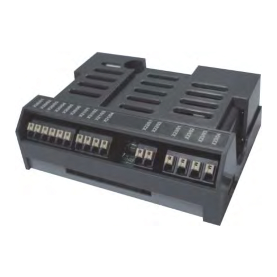
Page 10: User Terminals
User Terminals The GPIO range contains blocks of user terminals, as shown below. Digital Inputs and Outputs Analogue Inputs Thermistor Input Relay Outputs AC30 series General Purpose I/O Option... -
Page 11: Product Specification
Power consumption purpose is to power the (internal) option module, except digital outputs. Sourced from user supply. Maximum consumption Power consumption Its purpose is to power (7004-01-00 only) = (external) digital outputs. 500mA @ 24V AC30 series General Purpose I/O Option... -
Page 12: Digital Inputs And Outputs (7004-01-00 Only)
Digital input and output ports on the 7004-01-00 are fully isolated from the drive electronics. Therefore it is essential that X20/06 is connected to the user’s 0V signal reference which should be grounded at an appropriate point in the system. AC30 series General Purpose I/O Option... -
Page 13: Port Configuration
To select a port as an input, OUTPUT CONTROL must be OFF. Then if the user applies 24V to X20/01, INPUT reports a high level. If the user applies 0V, or open circuit to X20/01, INPUT reports a low level. AC30 series General Purpose I/O Option... -
Page 14: Programming
DOUT14 = low level output, or port is configured as input. DOUT14 = high level output 12 to Unused. Value = don’t care These control relay outputs 14, 15 on the GPIO. See page 17. AC30 series General Purpose I/O Option... - Page 15 DIN11 is low DIN11 is high DIN12 is low DIN12 is high Read 0005 only DIN13 is low DIN13 is high DIN14 is low DIN14 is high 12 to Not used. Value is always 0 AC30 series General Purpose I/O Option...
-
Page 16: Specifications
7004-01-00 Digital Isolation Inputs / Outputs. Isolation is functional only, intended to eliminate ground loops. It is not a safety isolation barrier. Conformance to standard EN61131-2:2007 State at power-up Off (low) AC30 series General Purpose I/O Option... -
Page 17: Example Applications
Example Applications Digital Input to DIN11: 24V PSU X20/01 (CLASS II) X20/06 Digital Output from DOUT11: X20/01 X20/05 24V PSU LOAD (CLASS II) X20/06 AC30 series General Purpose I/O Option... -
Page 18: Analogue Inputs (7004-01-00 Only)
See the example application on page 14. If any analogue inputs ANIN11 to ANIN13 are unused, they should be connected to X21/01 (AN 0V) to prevent invalid values being reported. AC30 series General Purpose I/O Option... -
Page 19: Programming
X21/01 Overrange >2% Accuracy Better than ±1% Absolute maximum input -20V to +20V relative to terminal voltage X21/01 Input impedance >50kΩ Resolution 12 bits + sign Sample rate Conformance to standard EN61131-2:2007 AC30 series General Purpose I/O Option... -
Page 20: Example Application
Example Application ±10V Analogue Input to ANIN11 X21/01 10V PSU (CLASS II) X21/02 10V PSU (CLASS II) AC30 series General Purpose I/O Option... -
Page 21: Motor Thermistor (7004-01-00, 7004-02-00 And 7004-03-00)
0 to 1004 4500Ω Drive trips if thermistor Read resistance is less than this trip level. Drive trips if thermistor resistance exceeds this trip level. Read 0 to Actual thermistor resistance 1185 only 4500Ω AC30 series General Purpose I/O Option... -
Page 22: Specification
Important safety information: Insulation and routing of wiring to the GPIO thermistor terminals must be appropriately rated to ensure the correct degree of insulation to other user wiring. Example Application X22/01 Motor Thermistor X22/02 AC30 series General Purpose I/O Option... -
Page 23: Volt-Free Relays (7004-01-00 Only)
I/O on this board and on the base control board. RLY11 is OFF. Contacts are open. Write 00022 RLY11 is ON. Contacts Read are closed. RLY12 is OFF. Contacts are open. RLY12 is ON. Contacts are closed. AC30 series General Purpose I/O Option... -
Page 24: Specification
300 x 10 operations (Electrical) Expected life 20 x 10 operations (Mechanical) Example application Relay Output RLY11 to 230VAC Load: X23/01 230V AC X23/02 LOAD Note: the load must be earthed, if necessary, for safety. AC30 series General Purpose I/O Option... -
Page 25: Real-Time Clock (7004-01-00 And 7004-03-00)
MM = calendar month (Range 01 to 12) DD = day of the month (Range 01 to 31) HH = hour (Range 0 to 23) MM = minutes (Range 0 to 59) SS = seconds (Range 0 to 59) AC30 series General Purpose I/O Option... -
Page 26: Specification
±5 minutes / month Battery backup duration. This is the minimum length of time the RTC will 6 months continue to run while the drive is unpowered. Automatic adjustment for daylight saving Not supported AC30 series General Purpose I/O Option... -
Page 27: Environmental
Council of 18 December 2006 concerning the Registration, Evaluation, Authorization, and Restriction of Chemicals (REACH) entered into force on June 1, 2007. Parker agrees with the purpose of REACH which is to ensure a high level of protection of human health and the environment. -
Page 28: Waste Electrical And Electronic Equipment (Weee)
Parker Hannifin Company, together with local distributors and in accordance with EU directive 2002/96/EC, undertakes to withdraw and dispose of its products, fully respecting environmental considerations. For more information about how to recycle your Parker supplied waste equipment, please contact your local Parker Service Centre. Packaging During transport our products are protected by suitable packaging. - Page 29 (from AT, BE, CH, CZ, DE, EE, ES, FI, FR, IE, IL, IS, IT, LU, MT, NL, NO, PT, SE, SK, UK) © 2012 Parker Hannifi n Corporation. All rights reserved. Parker Hannifi n Manufacturing Limited, Automation Group, SSD Drives Europe,...
Need help?
Do you have a question about the AC30 series and is the answer not in the manual?
Questions and answers