
Related Manuals for CEL-MAR ADA-13021MG


Summary of Contents for CEL-MAR ADA-13021MG
-
Page 1: User Manual
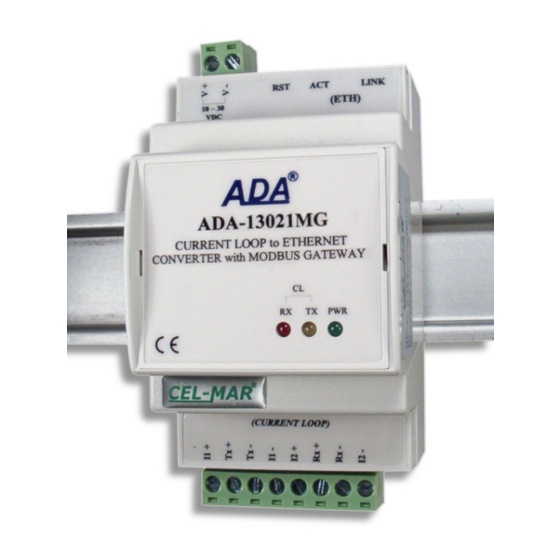
ADA-13021MG User manual ADA-13021MG Current Loop to ETHERNET converter with MODBUS GATEWAY Copyright © 2001-2018 CEL-MAR sp.j. io_ada-13021mg_v1.01_en... -
Page 2: Table Of Contents
ADA-13021MG Contents 1. GENERAL INFORMATION..................................4 1.1. WARRANTED INFORMATION............................... 4 1.2. GENERAL CONDITIONS FOR SAFE USE............................ 4 1.3. CE LABEL....................................... 4 1.4. ENVIRONMENTAL PRESERVATION............................4 1.5. SERVICE AND MAINTENANCE..............................4 1.6. PACK CONTENTS..................................4 2. PRODUCT INFORMATION..................................4 2.1. PROPERTIES....................................4 2.2. - Page 3 ADA-13021MG 5.2.6.4. FACTORY DEFAULT SETTINGS..........................28 5.2.6.5. SYSTEM INFORMATION............................28 5.2.6.6. REBOOT..................................28 5.2.6.7. LOGOUT – ENDING MANAGEMENT AND CONFIGURATION.................28 6. USING VIRTUAL PORT SERVICE [REALPORT]..........................28 6.1. VIRTUAL PORT DRIVER INSTALLATION IN WINDOWS XP.....................28 6.2. REALPORT CONFIGURATION IN WINDOWS XP........................28 7.
-
Page 4: General Information
1.1. WARRANTED INFORMATION ADA-13021MG converter is covered by a two year warranty from date of sale. In case of being damaged it will be repair or the damaged component will be replace. The warranty does not cover damage caused from improper use, materials consumption or any unauthorized changes. -
Page 5: Description
RX+,RX-,TX+,TX- of CL interface. To Current Loop line based on ADA-13021MG can be connected in point-to-point topology devices operate in half duplex or full duplex mode. This converter has internal, low energy surge protection for each Current Loop lines however it is recommended to use the external lightning arresters (typical protection of telephone line) for the lightning protection of lines. -
Page 6: Communications In The Virtual Serial Port Mode (Realport)
2.4.1. CURRENT LOOP TRANSMITTER The Current Loop transmitter in ADA-13021MG was made as a passive 0-20mA(TTY), having low energy short circuit protection on TX+ and TX- lines. By the correct connection of the transmitter with power source I1, Current Loop transmitter 0-20mA can operate as active. -
Page 7: Installation
ADA-13021MG 3. INSTALLATION This chapter will show how to connect ADA-13021MG to Current Loop bus, LAN/WAN network and power supply and how to use it. In the purpose of minimization of disruptions from environment is being recommended to: ● apply multipair type shielded cables, which shield can be connected to the earthing on one end of the cable, ●... -
Page 8: Connecting To Network Adapter Of Pc
3.2.1. CONNECTING TO NETWORK ADAPTER OF PC If there is not the switch or the HUB, it is possible to connect the ADA-13021MG directly to a network adapter of PC using the cross- over cable (Table 2). This connection can be used for converter configuration. -
Page 9: Connection For Operating In Tcp & Udp Serial Bridge Mode
Fig. 7. The WAN connection to operating in the Real Port mode 3.2.3. CONNECTION FOR OPERATING IN TCP & UDP SERIAL BRIDGE MODE Pictures below show how correctly connect the ADA-13021MG to ETHERNET network to operating in TCP and UDP serial bridge mode. - Page 10 ADA-13021MG Local network ETHERNET based on the switch ETHERNET ETHERNET Straight cable Straight cable (Table 1) MASTER Device (Table 1) with Current Loop ADA-13021MG SLAVE Device with interface Static IP address Current Loop interface ADA-13021MG Static IP address Current Loop...
-
Page 11: Converters Connection As Modbus Gateway
ADA-13021MG 3.2.4. CONVERTERS CONNECTION AS MODBUS GATEWAY Figure below shows connection of ADA-13110MG to ETHERNET network ETHERNET(LAN) to operating in Industrial Automation Mode (MODBUS Gateway). This type of connection allows integrating MODBUS-TCP devices and MODBUS-RTU/ASCII devices in one network. ADA-130210MG... -
Page 12: Connection To Current Loop Devices
Rx - Passive Transmitter I2 - Power supply Vss+ Vss- Fig. 11. Example connection of device with passive transmitter and passive receiver to ADA-13021MG 3.3.2. CONNECTION TO DEVICE WITH ACTIVE TRANSMITTER & ACTIVE RECEIVER Current Loop ADA-13021MG Device ETHERNET Current Loop... -
Page 13: Connection To Device With Active Transmitter & Passive Receiver
3.4. POWER SUPPLY CONNECTION The power supply to ADA-13021MG converter should be DC (regulated) from 10 V= to 30V=. Nominal power is typically 3W, e.g. ZS- 12/250 or DR-15-24. Power cable from DC power supplies to device must not be longer than 3m. -
Page 14: Activation
ADAFinder is use for initial configuration of converter's network setting. Before running ADAFinder should be disabled the System FireWall! After running, the program is searching local network and if find ADA-13021MG, will add them to the list of available converters [Devices:] Fig.15. - Page 15 ADA-13021MG Fig. 15. Base configuration network by the use ADAFinder software Fig. 16. ADAFinder configuration of IP network address...
-
Page 16: Configuration And Management By The Use Of Internet Browser
ADA-13021MG 5.2. CONFIGURATION AND MANAGEMENT BY THE USE OF INTERNET BROWSER Integrated WWW server to ADA-13021MG enable to easy configuration and diagnostics of LAN and WAN network devices by the use Internet browser. For configuration open the Internet Browser and type the address http://<converter-ip-address>/admin/administration.htm. The login windows will open. -
Page 17: Serial Port Configuration
Fig. 18. The web page for network setting of ADA-13021MG 5.2.2. SERIAL PORT CONFIGURATION The configuration of serial port (Current Loop) of ADA-13021MG converter includes: port description, setting of port profile (operating mode) and setting of serial transmission parameters (baud rate, data bits, parity, stop bits). -
Page 18: Realport (Virtual Port) Configuration
5.2.2.1.1. REALPORT (VIRTUAL PORT) CONFIGURATION Choosing RealPort (Virtual Port, Fig. 19) is configured the serial port of ADA-13021MG, for communication with virtual port COM of computer. Press [Apply] for save. After installation driver (RealPort) of virtual port COM (see chapter 6) in operating system, data sending by application to this port are transferred through WLAN/WAN to ADA-13021MG converter and are present on his serial port. -
Page 19: The 'Enable Tcp Keep-Alive' Option Configuration
ADA-13021MG Fig. 20. Example configuration of TCP server For configuration of TCP Client Settings (TCP Client Setting, fig. below), select Automatically establish TCP connections, connection between client and TCP server will be automatically. Then select Always connect and maintain connection option and in section Establish connection to the following network service enter IP address of device to which TCP client will send data, select service and enter port. -
Page 20: Serial Port Transmission Parameters Configuration
ADA-13021MG 5.2.2.1.2.3. SERIAL PORT TRANSMISSION PARAMETERS CONFIGURATION For proper operation of ADA-13021MG with device connected to his serial port (Current Loop), should be set the same transmission parameters for both devices. Select Basic Serial Settings and enter Baud Rate, Data Bits, Parity, Stop Bits, the same parameter like has device connected to the serial port of the converter. -
Page 21: Udp Client & Server Configuration In Case Of Slave Device
2101 port. Then select Automatically send serial data in section UDP Client Settings, this automatically send received data by the use UDP client service to the MASTER device connected to LAN / WAN through e.g. ADA-13021MG, ADA-13040, ADA-13110, ADA14040, ADA-14040. -
Page 22: Serial Port Transmission Parameters Configuration
5.2.2.1.4.1. SERIAL PORT TRANSMISSION PARAMETERS CONFIGURATION For proper operation of ADA-13021MG with device connected to his serial port (Current Loop), should be set the same transmission parameters for both devices. - Page 23 ADA-13021MG Fig. 26. Example configuration for communication with MODBUS-MASTER devices – Modbus RTU setting Then select section Slave Destinations (Packet Routing) – figure below. In this section press [Add], enter the IP address of Slave type devices, to which Master will send requests and receive responses.
- Page 24 ADA-13021MG Fig. 28. Example configuration for communication with MODBUS-MASTER devices – table entry configuration for SLAVE type devices On section Advanced Protocol Settings (fig. below), set the time out by entry: – Character timeout - value in ms., maximum delay or gap betweens bytes of a message – default 20 ms.
-
Page 25: Configuration For Communication With Modbus-Slave Type Device
In section Industrial Automation Settings, press [Change Protocol] link. Then in section Select IA Protocol (figure below) select type of device, connected to serial port of ADA-13021MG as Serial Slave and MODBUS-RTU or MODBUS-ASCII protocol for communication between connected devices. Press [Apply] for saving configuration. -
Page 26: Serial Port Transmission Parameters
SLAVE type device 5.2.2.1.5.3. SERIAL PORT TRANSMISSION PARAMETERS For proper operation of ADA-13021MG with devices Modbus-Master or Modbus-Slave types, connected to his serial port, should be set the same transmission parameters for both devices. Select Basic Serial Settings and enter Baud Rate, Data Bits, Parity, Stop Bits, the same parameter like has device connected to the serial port of the converter. -
Page 27: Changing User Mane And Password
Allow command line access – access using the Command Line Interface - telnet, Allow web interface access – access using the internet browser. C/ User Permissions - user permissions to configuration and management of the ADA-13021MG converter, where are options: None - no permission, Read - permission to read, Read Self - permission to read own settings, but not other users. -
Page 28: Factory Default Settings
2. Double click icon [ Administrative Tools] and [ Device Manager ] 3. Press [Ports (COM & LPT)]. On fig. 34 is shown available serial ports COM1, COM2 and COM3 marked as ADA-13021MG which was created after installation of RealPort driver. - Page 29 ADA-13021MG communication with virtual port driver. 9. In the next window press [OK] to accept the changes. Fig. 34. Devices view on Windows XP Fig. 35. Example configuration of multi-port serial adapter...
-
Page 30: Factory Default
ADA-13021MG - Electronic versions: Basic Current Loop Voltage: Order example: 24VDC Product symbol: ADA-13021MG-1-2-1-2 12VDC (standard version) 1 – standard electronics version, Current Loop Current: 2 – current loop voltage12VDC, 0 – 20 mA (standard version) 1 – current loop current 0-20mA, 2 –... -
Page 31: Specification
ADA-13021MG 10. SPECIFICATION TECHNICAL DATA Transmission Parameters Net/ Interface ETHERNET Current Loop Connector RJ45 Screw terminal, wire max. Ø 2,5mm Depend on baud rate, up to few Max. Line length LAN up to 150 m kilometres Do 38,4 kbps (depend on current loop Max. - Page 32 Thank you for purchasing CEL-MAR Company products. We hope that this user manual helped connect and start up the ADA-13021MG converter. We also wish to inform you that we are a manufacturer of the widest selections of data communications products in the world such as: data transmission converters with interface RS232, RS485, RS422, USB, Current Loop, Fibre-Optic Converters and Ethernet or Wi-Fi.
Need help?
Do you have a question about the ADA-13021MG and is the answer not in the manual?
Questions and answers