
Related Manuals for CEL-MAR ADA-1040PC9


Summary of Contents for CEL-MAR ADA-1040PC9
- Page 1 ADA-1040PC9 User manual ADA-1040PC9 Kyma* KDU-110 to MODBUS-RTU protocol converter Copyright © 2001-2023 CEL-MAR sp.j. io_ada-1040pc9_v1.00_en...
-
Page 2: Table Of Contents
ADA-1040PC9 Contents 1. GENERAL INFORMATION..................................3 1.1. WARRANTED INFORMATION............................... 3 1.2. GENERAL CONDITIONS FOR SAFE USE............................ 3 1.3. CE LABEL....................................... 3 1.4. ENVIRONMENTAL PRESERVATION............................. 3 1.5. SERVICE AND MAINTENANCE..............................3 1.6. PACK CONTENTS..................................3 2. PRODUCT INFORMATION..................................3 2.1. PROPERTIES....................................3 2.2. -
Page 3: General Information
1.1. WARRANTED INFORMATION ADA-1040PC9 converter is covered by a two year warranty from date of sale. In case of being damaged it will be repair or the damaged component will be replace. The warranty does not cover damage caused from improper use, materials consumption or any unauthorized changes. -
Page 4: Description
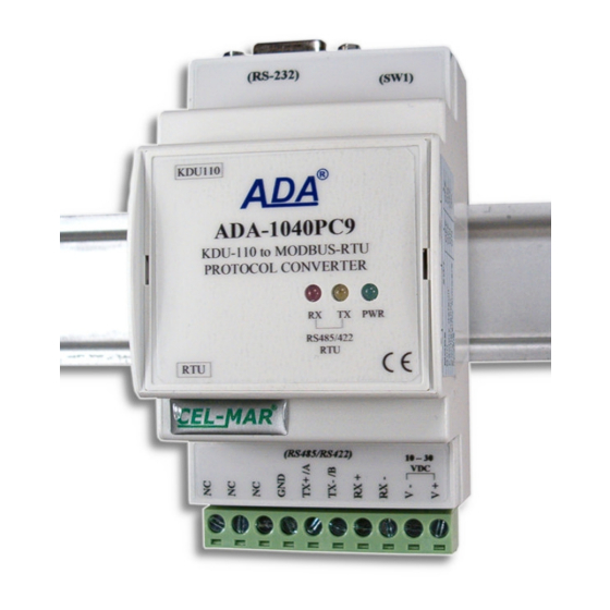
ADA-1040PC9 has DB-9F connector for connection RS232 interface of Kyma* KDU-110 and screw terminal block for connection of RS485/422 network and power supply. The DB-9F connector is DCE type to connecting RS232 interface. ADA-1040PC9 use Tx, Rx and GND for communication with RS232 interface. -
Page 5: Isolation
- not supply converter from power circuit device that generates large impulse interference such as transmitters, contactors. 3.1. ASSEMBLING The cover of ADA-1040PC9 converter is adapted to assembly on TS-35 (DIN35) rail. To install the converter, should be mounted on the rail upper part of the cover, then press bottom part to hear characteristic „Click” sound. -
Page 6: Connection To Kdu-110 Device
Fig. 5. ADA-1040PC9 connection to PC by the use of additional converter USB to RS232 (ADA-I9111 or ADA-I9110). 3.3. CONNECTION TO KDU-110 DEVICE In case of connection ADA-1040PC9 converter to communication port RS232 of KDU-110 device, should be made a cable according to diagram on fig. bellow. -
Page 7: Connection Of Kdu-110 Device To Rs485(2W) Modbus-Rtu Bus
RS232 4800Bd Fig. 8. Example connection of KDU-110 device by the use of ADA-1040PC9 to RS485(2W) 2-wire bus. 3.4.3. GND TERMINAL CONNECTION Connection of GND terminals of RS485/422 interfaces, devices connected to RS485/422 bus, should be done in the case of a potential difference of the signals grounds on interfaces RS485 / RS422, which prevents proper data transmission. -
Page 8: Troubleshooting
5.2. CONFIGURATION BY USING ADACONFIG The configuration of ADA-1040PC9 converter should be made by the use of ADAConfig Software - selling with converter. To make the configuration, connect converter to computer and power supply. If after power, on the front panel is not lit green LED PWR, check the power connection (polarity). -
Page 9: Factory Default
ADA-1040PC9 Fig. 9. View of ADAConfig software interface 5.3. FACTORY DEFAULT In case of faulty functioning ADA-1040PC9, can be restored the factory default setting of the converter internal registers. Set SW1 microswitch mode as in the table below. SW1-1 SW1-2 Disconnect the power and after while connect again the power. -
Page 10: Emergency Firmware Update
SW1-2 After microswitch setting, should be restarted ADA-1040PC9, by turning OFF and then ON the power supply. The yellow LED will light continuously and the converter will be in Emergency Firmware Update mode. Now follow the description in the above point. -
Page 11: Implementation Of Modbus-Rtu Protocol
Fig. 11. Connection of KDU-110 to RS485 MODBUS-RTU bus. 8. IMPLEMENTATION OF MODBUS-RTU PROTOCOL ADA-1040PC9 protocol converter allows connecting KDU-110 device as SLAVE to RS485 MODBUS-RTU bus. The length of RS485 bus can be extended (another 1200m) by the use of ADA-4040 repeaters or ADA-4044H HUBs RS485. -
Page 12: Registers Of Current Parameter Values Kdu-110 Device - Readout By Function 03 (4X - References) Holding Registers
ADA-1040PC9 Address Registers Register Attribute Value Address description 30006 THRUST [T] 16-bit register U32 LO THRUST DWORD = 1108 = 0x00 00 04 54 DW=10 WORD LO = 0x204 54; BYTE HI = 0x04; BYTE LO = 0x54 30007 16-bit register... -
Page 13: Frame Structure Of Modbus-Rtu Protocol
ADA-1040PC9 Address Registers Register Attribute Value Address description 40007 16-bit register THRUST DWORD = 1108 = 0x00 00 04 54 U32 HI WORD HI = 0x00 00; BYTE HI = 0x00; BYTE LO = 0x00 DW=10 40008 16-bit register RPM [rpm]... - Page 14 "Total parameter value = %d\n, hundredth parts of the parameter value = %d\n", div_ValueParam .quot, div_ValueParam .rem ); Query about TORQUE Byte no Designation Size Value [hex] ADA-1040PC9 address 1 Byte 11 [ 1 to F7] Function code 1 Byte 03 / 04 Registry address Hi 1 Byte...
-
Page 15: Rs232 Interface - Pin Description Of Dsub-9F-Dce Socket
ADA-1040PC9 ATTENTION ! TO ADA-1040PC9 CAN BE SENT ALSO MODBUS-RTU QUERY ABOUT ALL OR SELECTED REGISTERS OF KDU-110 DEVICE. 9. RS232 INTERFACE – PIN DESCRIPTION OF DSUB-9F-DCE SOCKET Signal Description ADA-1040PC9 (DCD) Level of receiver signal Connected with DSR (TxD) - Page 16 Thank you for purchasing CEL-MAR Company products. We hope that this user manual helped connect and start up the ADA-1040PC9 converter. We also wish to inform you that we are a manufacturer of the widest selections of data communications products in the world such as: data transmission converters with interface RS232, RS485, RS422, USB, Current Loop, Fibre-Optic Converters and Ethernet or Wi-Fi.
Need help?
Do you have a question about the ADA-1040PC9 and is the answer not in the manual?
Questions and answers