
Subscribe to Our Youtube Channel
Related Manuals for CEL-MAR ADA-13110MG


Summary of Contents for CEL-MAR ADA-13110MG
- Page 1 ADA-13110MG User manual ADA-13110MG RS232 to ETHERNET converter with MODBUS GATEWAY Copyright © 2001-2020 CEL-MAR sp.j. io_ada-13110mg_v.1.1_en...
-
Page 2: Table Of Contents
3.2.3. CONNECTION FOR OPERATING IN TCP & UDP SERIAL BRIDGE MODE..............8 3.2.4. CONVERTERS CONNECTION AS MODBUS GATEWAY....................10 3.3. RS232 DEVICES CONNECTION TO ADA-13110MG.........................10 3.3.1. CONNECTING OF DEVICE WITH RS232 PORT, DTE TYPE (PC COMPUTER).............10 3.3.2. CONNECTING OF DEVICE WITH RS232 PORT, DCE TYPE (MODEM, CODE READER)..........11 3.4. - Page 3 ADA-13110MG 6. USING VIRTUAL PORT SERVICE [REALPORT]..........................24 6.1. VIRTUAL PORT DRIVER INSTALLATION IN WINDOWS XP....................24 6.2. REALPORT CONFIGURATION IN WINDOWS XP........................25 7. FACTORY DEFAULT................................... 27 8. TROUBLESHOOTING..................................27 9. VERSIONS......................................27 10. SPECIFICATION....................................27...
-
Page 4: General Information
1.1. WARRANTED INFORMATION ADA-13110MG converter is covered by a two year warranty from date of sale. In case of being damaged it will be repair or the damaged component will be replace. The warranty does not cover damage caused from improper use, materials consumption or any unauthorized changes. -
Page 5: Description
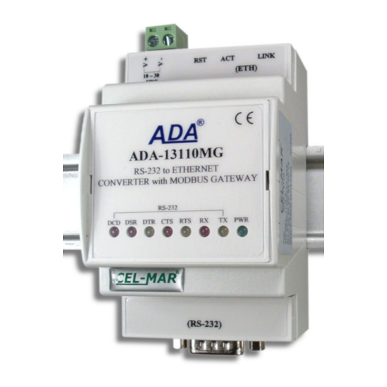
MODBUS-RTU/ASCII with MODBUS-TCP devices within one network. Can be configured and managed via Internet browser – converter has implemented WWW server. ADA-13110MG has standard DB- 9M (male) RS232 connector, screw terminal block for connecting the power supply and RJ45 modular connector for ETHERNET network connection. -
Page 6: Ethernet Network Communication
3.2. ETHERNET NETWORK CONNECTION ADA-13110MG has to be connected to ETHERNET network by the use of the switch, the HUB or directly to the PC network adapter. The table below shows preparing of the straight cable for converter connection to switch or hub. -
Page 7: Connecting To Network Adapter Of Pc
3.2.1. CONNECTING TO NETWORK ADAPTER OF PC If there is not the switch or the HUB, it is possible to connect the ADA-13110MG directly to a network adapter of PC using the cross- over cable (Table 2). This connection can be used for converter configuration. -
Page 8: Connection For Operating In Tcp & Udp Serial Bridge Mode
Fig. 5. WAN connection to operating in the Real Port mode 3.2.3. CONNECTION FOR OPERATING IN TCP & UDP SERIAL BRIDGE MODE Pictures below show how correctly connect the ADA-13110MG to ETHERNET network for functioning in TCP & UDP serial bridge mode. - Page 9 ADA-13110MG Local network ETHERNET built on the switch ETHERNET ETHERNET Straight Cable Straight Cable (Table 1) (Table 1) Device with Device with RS232 interface RS232 interface ADA-13110MG ADA-13110MG Static IP address Static IP address RS232 RS232 Fig. 6. The LAN connection to operating in the TCP/UDP serial bridge mode, one-to-one...
-
Page 10: Converters Connection As Modbus Gateway
3.3.1. CONNECTING OF DEVICE WITH RS232 PORT, DTE TYPE (PC COMPUTER) ADA-13110MG can be connected to RS232 port of PC computer by the use of RS232 extension cable CAB-DB9F/DB9F-C-1,8m (available in our offer). Picture below shows the example connecting to RS232 PC port. -
Page 11: Connecting Of Device With Rs232 Port, Dce Type (Modem, Code Reader)
3.4. POWER SUPPLY CONNECTION The power supply to the ADA-13110MG converter should be DC (regulated) from 10 V= to 30V=. Nominal power is typically 3W, e.g. HDR-15-24. Power cable from DC power supplies to device must not be longer than 3m. -
Page 12: Initial Configuration Using Adafinder Software
ADAFinder is use for initial configuration of converter's network setting. Before running ADAFinder should be disabled the System FireWall! After running, the program is searching local network and if find ADA-13110MG, will add them to the list of available converters [Devices:], like on the picture below. -
Page 13: Configuration And Management By The Use Of Internet Browser
Fig 12. ADAFinder configuration of IP network address 5.2. CONFIGURATION AND MANAGEMENT BY THE USE OF INTERNET BROWSER Integrated WWW server to ADA-13110MG enable to easy configuration and diagnostics of LAN and WAN network devices by the use Internet browser. -
Page 14: Network Configuration
5.2.1. NETWORK CONFIGURATION To make changes of default setting or new configuration of ADA-13110MG, select on left panel Configuration -> Network and then on right [IP Settings] (Fig.13) and make the selection: Obtain an IP address automatically using DHCP or Use the following IP address (in this option, enter IP Address of the converter, Subnet Mask, Default Gateway), press [Apply] for save. -
Page 15: Realport (Virtual Port) Configuration
5.2.2.1.1. REALPORT (VIRTUAL PORT) CONFIGURATION Choosing RealPort (Virtual Port, Fig. 15) is configured the serial port of ADA-13110MG, for communication with virtual port COM of computer. Press [Apply] for save. After installation driver (RealPort) of virtual port COM (see chapter 6) in operating system, data sending by application to this port are transferred through WLAN/WAN to ADA-13110MG converter and are present on his serial port. -
Page 16: The 'Enable Tcp Keep-Alive' Option Configuration
ADA-13110MG Fig. 16. Example configuration of TCP server For configuration of TCP Client Settings (TCP Client Setting, fig. below), select Automatically establish TCP connections, connection between client and TCP server will be automatically. Then select Always connect and maintain connection option and in section Establish connection to the following network service enter IP address of device to which TCP client will send data, select service and enter port. -
Page 17: Serial Port Transmission Parameters Configuration
ADA-13110MG 5.2.2.1.2.3. SERIAL PORT TRANSMISSION PARAMETERS CONFIGURATION For proper operation of ADA-13110MG with device connected to his serial port, should be set the same transmission parameters for both devices. Select Basic Serial Settings and enter Baud Rate, Data Bits, Parity, Stop Bits, the same parameter like has device connected to the serial port of the converter. -
Page 18: Udp Client & Server Configuration In Case Of Slave Device
. 5.2.2.1.3.3. SERIAL PORT TRANSMISSION PARAMETERS CONFIGURATION For proper operation of ADA-13110MG with device connected to his serial port, should be set the same transmission parameters for both devices. -
Page 19: Serial Bridge Profile Configuration
5.2.2.1.4.1. SERIAL PORT TRANSMISSION PARAMETERS CONFIGURATION For proper operation of ADA-13110MG with device connected to his serial port, should be set the same transmission parameters for both devices. - Page 20 ADA-13110MG Fig. 21. Example configuration for communication with MODBUS-MASTER devices – choice of devices and protocols Set the options in section Modbus RTU Settings like on the figure below and press [Apply]. Fig. 22. Example configuration for communication with MODBUS-MASTER devices – Modbus RTU setting Then select section Slave Destinations (Packet Routing) –...
-
Page 21: Configuration For Communication With Modbus-Slave Type Device
In section Industrial Automation Settings, press [Change Protocol] link. Then in section Select IA Protocol (figure below) select type of device, connected to serial port of ADA-13110MG as Serial Slave and MODBUS-RTU or MODBUS-ASCII protocol for communication between connected devices. Press [Apply] for saving configuration. - Page 22 ADA-13110MG Fig. 26. Example configuration for communication with MODBUS-SLAVE devices – choice of devices and protocols Set options in section [Modbus RTU Settings] eg. As on picture below. Press [Apply] for saving configuration. Fig. 27. Example configuration for communication with MODBUS-SLAVE devices – Modbus RTU setting Go to section Modbus/TCP Network Settings [Global], configuration options set as on the figure below.
-
Page 23: Serial Port Transmission Parameters
On the configuration page Users are two sections: – Users – Configure Users The section Users allows configuring the method of login to ADA-13110MG. Selecting the option Enable user logins means that after enter the address http://<ip- c on v erter- address >/admin/administration.htm to internet browser, will open login window and will be necessary to enter user name and password. -
Page 24: Management
- Network – show statistics of ETHERNET interface for IP, TCP, UDP, ICM protocols. 5.2.6.6. REBOOT Section Reboot allows making software reset of ADA-13110MG. Pressing [Reboot] will start rebooting of server during 1 min. 5.2.6.7. LOGOUT – ENDING MANAGEMENT AND CONFIGURATION After completion of the configuration or administration should be pressing Logout on left panel –... -
Page 25: Realport Configuration In Windows Xp
2. Double click icon [ Administrative Tools] and [ Device Manager ] 3. Press [Ports (COM & LPT)]. On fig. 30 is shown available serial ports COM1, COM2 and COM3 marked as ADA-13110MG which was created after installation of RealPort driver. - Page 26 ADA-13110MG Fig. 31. Example configuration of multi-port serial adapter...
-
Page 27: Factory Default
9. VERSIONS ADA-13110MG - Electronic versions: Basic Order example: Galvanic isolation: Product Symbol: ADA-13110MG-1-2 1 – basic version of electronic, 1kV= from the power supply 2 - galvanic isolation 1kV= from the power supply 3kV= from the power supply 1kV= 3-way 3kV= 3-way Isolation from the power supply allows transmitting signals: Tx, Rx, RTS, CTS, DTR, DSR, DCD of RS232 interface. - Page 28 Thank you for purchasing CEL-MAR Company product. We hope that this user manual helped connect and start up the ADA-13110MG Converter with MODBUS GATEWAY. We also wish to inform you that we are a manufacturer of the widest selections of data communications products in the world such as: data transmission converters with interface RS232, RS485, RS422, USB, Ethernet, Wi-Fi, Current Loop, Fibre-Optic Converters and the other.
Need help?
Do you have a question about the ADA-13110MG and is the answer not in the manual?
Questions and answers