
Related Manuals for CEL-MAR ADA-13040MG


Summary of Contents for CEL-MAR ADA-13040MG
-
Page 1: User Manual
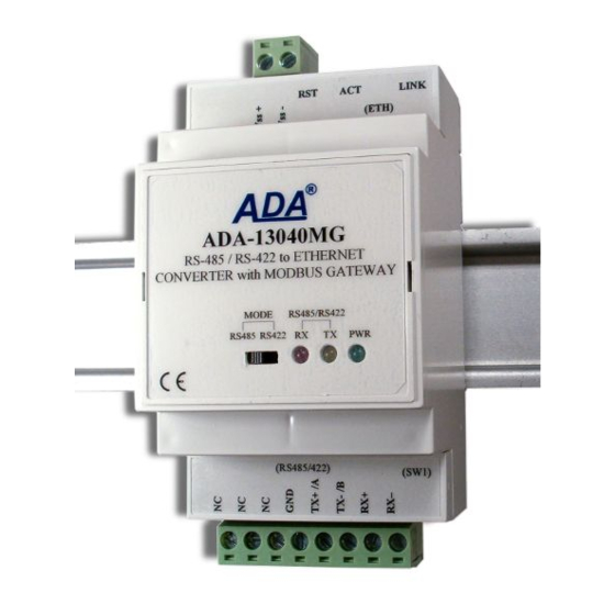
ADA-13040MG User manual ADA-13040MG ETHERNET to RS485/RS422 Converter with MODBUS GATEWAY Copyright © 2001-2013 CEL-MAR sp.j. io_ada-13040MG_en_v0.10... -
Page 2: Table Of Contents
ADA-13040MG Contents 1. GENERAL INFORMATION..................................4 1.1. WARRANTED INFORMATION ..............................4 1.2. GENERAL CONDITIONS FOR SAFE USE............................ 4 1.3. CE LABEL....................................... 4 1.4. ENVIRONMENTAL PRESERVATION............................4 1.5. SERVICE AND MAINTENANCE..............................4 2. PRODUCT INFORMATION..................................4 2.1. PROPERTIES....................................4 2.2. DESCRIPTION....................................5 2.3. - Page 3 ADA-13040MG 6. USING VIRTUAL PORT SERVICE [REALPORT] ..........................24 6.1. VIRTUAL PORT DRIVER INSTALLATION IN WINDOWS XP....................24 6.2. REALPORT CONFIGURATION IN WINDOWS XP........................25 7. FACTORY DEFAULT.................................... 26 8. PROBLEMS......................................26 9. VERSIONS......................................27 10. DANE SPECIFICATION..................................27...
-
Page 4: General Information
1.1. WARRANTED INFORMATION The ADA-13040MG converter is covered by a two year warranty from date of sale. In case of being damaged it will be repair or the damaged component will be replace. The warranty does not cover damage caused from improper use, materials consumption or any unauthorized changes. -
Page 5: Description
Converter uses protocols: TCP, UDP, DHCP, SNMP, SSL/TLS, Telnet, Rlogin, LPD, HTTP/HTTPS, SMTP, ICMP, IGMP, ARP. It has a built-in WWW web server what allow you to configure and menage it via internet browser. The ADA-13040MG supports the baud rate 230,4 kbps via RS485/RS422 interface and use RX+,RX-,TX+(A),TX-(B) signals. -
Page 6: Communications In The Serial Bridge Mode
"Click" sound. 3.2. ETHERNET NETWORK The ADA-13040MG has to be connected to ETHERNET network by the use of the switch, the HUB or directly to the PC network adapter. -
Page 7: Connecting To Network Adapter Of Pc
3.2.1. CONNECTING TO NETWORK ADAPTER OF PC If there is not the switch or the HUB, it is possible to connect the ADA-13040MG directly to a network adapter of PC using the cross- over cable (Table 2). This connection can be used for converter configuration. -
Page 8: Connection For Functioning In Tcp & Udp Serial Bridge Mode
Fig 5. The WAN connection to functioning in the Real Port mode 3.2.3. CONNECTION FOR FUNCTIONING IN TCP & UDP SERIAL BRIDGE MODE Fig. 6, 7 below show how correctly connect the ADA-13040MG to ETHERNET network to functioning in TCP and UDP serial bridge mode. -
Page 9: Converters Connection As Modbus Gateway
Fig 7. The LAN connection to functioning in the UDP serial bridge mode, one-to-many 3.2.4. CONVERTERS CONNECTION AS MODBUS GATEWAY Figure 8 shows correct connection of ADA-13040MG to ETHERNET network Wi-Fi (LAN) to functioning in Industrial Automation Mode (MODBUS Gateway). This type of connection allows to integrate MODBUS-TCP devices and MODBUS-RTU/ASCII devices in one network. -
Page 10: Rs485/Rs422 Bus
The ADA-13040MG allows functions on the RS422 and RS485 Bus. Both buses require proper wiring. 3.3.1. CONNECTION TO 4-WIRE RS422 BUS Before connection 4-wire RS422 Bus, should be set the MODE switch on the front panel of ADA-13040MG in RS422 mode. Connect wires of bus to terminals TX+/A, TX-/B, RX+, RX-, like below. -
Page 11: Line Termination
3.4. POWER SUPPLY CONNECTION The power supply to the ADA-13040MG should be DC (regulated) from the scope 10 V= to 30V= and nominal power more then 3W. Power cable from DC power supplies to device must not be longer than 3m. Observe the polarity, connect positive (+) of DC power supplies to V+ and negative (-) end to V- terminal. -
Page 12: Rs485/ Rs422 Operating Mode
5.2.2. NETWORK SETTING Before running the ADAFinder should be disabled the System FireWall! After running, the program is searching local network and if find ADA-13040MG, will add them to the list of available port servers [Devices:] Fig.12. To change the network setting of ADA-13040MG, should:... -
Page 13: Configuration And Management With Use Of Internet Browser
Rys 13. View of ADAFinder configuring IP address windows 5.3. CONFIGURATION AND MANAGEMENT WITH USE OF INTERNET BROWSER Integrated WWW server to ADA-13040MG enable to easy configuration and diagnostics of LAN and WAN network devices with use Internet browser. For configuration open the Internet Browser and type the address http://<converter-ip-address>/admin/administration.htm. The login windows will open. -
Page 14: Network Configuration
5.3.1. NETWORK CONFIGURATION To make a changes of default setting or new configuration of ADA-13040MG, select on left panel Configuration -> Network and then on right [IP Settings] (Fig.15) and make the selection: Obtain an IP address automatically using DHCP or Use the following IP address (in this case, enter IP Address of the converter, Subnet Mask, Default Gateway), press [Apply] for save. -
Page 15: Realport (Virtual Port )
5.3.2.1.2. TCP SOCKETS Choosing TCP Sockets is configured the serial port of ADA-13040MG, for communication with PC by the use of TCP socked. Data sending by application to TCP socked are transferred through network. to ADA-13040MG converter and are present on his serial port... -
Page 16: Tcp Server And Client
ADA-13040MG 5.3.2.1.2.1. TCP SERVER AND CLIENT After saving the TCP Sockets profile, will open section TCP Server Settings (picture below), includes configuration of: – port for Telnet service; standard 2001, – port for serial port service; standard 2101 (through this port are transferred data to serial port of converter), –... -
Page 17: Serial Port Transmission Parameters
- Probe Count – the number of times TCP probes the connection to determine (scope 5 – 30 trials). 5.3.2.1.2.3. SERIAL PORT TRANSMISSION PARAMETERS For proper operation of ADA-13040MG with device connected to his RS485/RS422 serial port, should be set the same transmission parameters for both devices. -
Page 18: Udp Client & Server Configuration In Case Of Slave Device
5.3.2.1.3.2. UDP CLIENT & SERVER CONFIGURATION IN CASE OF SLAVE DEVICE Set operating parameters of UDP server for SLAVE device connected via serial port to ADA-13040MG, eg like on picture below. Set an access to UDP server on e.g. 2101 port. Then select Automatically send serial data in section UDP Client Settings, this automatically send received data by the use UDP client service to t he MASTER device connected to LAN / WAN through e.g. -
Page 19: Serial Port Transmission Parameters
After saving the Serial Bridge profile, will open section Serial Bridge Settings with operating parameters like on picture below. Select Initiate serial bridge to the following device option and enter IP address and 2101 Port of ADA-13040MG with which to create the serial bridge over the network. -
Page 20: Communication With Devices Modbus-Master Type
In section Industrial Automation Settings, press [Change Protocol] link. Then in section Select IA Protocol (figure below) select type of device, connected to serial port of ADA-13040MG, as Serial Master and MODBUS-RTU or MODBUS-ASCII protocol for communication between connected devices. Press [Apply] for saving configuration. - Page 21 ADA-13040MG Fig 25. Example configuration for communication with MODBUS-MASTER devices - type of devices and protocol Next section is Advanced Protocol Settings (fig. below), set the time outs : - Character timeout - value in ms., maximum delay or gap betweens bytes of a message – default 20 ms.
-
Page 22: Configuration For Communication With Modbus-Slave Type Device
5.3.2.1.5.3. SERIAL PORT TRANSMISSION PARAMETERS For proper operation of ADA-13040MG with device connected to his RS485/RS422 serial port, should be set the same transmission parameters for both devices. -
Page 23: System Settings
- Serial Ports - Connections 5.3.5.1. SERIAL PORTS MANAGEMENT Section Serial Ports allows to identification connections/disconnection to the serial port of ADA-13040MG through the network. 5.3.5.2. CONNECTIONS MANAGMENT Section Connections allows to identification connections/disconnection to the ADA-13040MG through the network. -
Page 24: Backup & Restore Configuration
- Network – show statistics of ETHERNET interface for IP, TCP, UDP, ICM protocols. 5.3.6.6. REBOOT Section Reboot allows to make software reset of ADA-13040MG. Pressing [Reboot] will start rebooting of server during 1 min. 5.3.6.7. LOGOUT – ENDING THE MANAGEMENT If all the configuration were done, press Logout on left panel. -
Page 25: Realport Configuration In Windows Xp
2. Double click icon [ Administrative Tools] and [ Device Manager ] 3. Press [Ports (COM & LPT)]. On fig. 29 is shown available serial ports COM1, COM2 and COM3 marked as ADA-13040MG which was create after installation of RealPort driver. -
Page 26: Factory Default
2. Remove the cover of Serial Server Wi-Fi connector, 3. Press RESET “RST” and holding the button turn the power on of ADA-13040MG, 4. Release the button and after 20 sec. the Serial Server will start with Default Settings (sec. 7). -
Page 27: Versions
ADA-13040MG - Electronic versions: Basic Galvanic isolation: Order example: 1kV DC (2-WAY) Product Symbol: ADA-13040MG-1-23-3 3kV DC (2-WAY) 1 – basic version of electronic,, 1kV DC (3-WAY) 23 - galvanic isolation 1kV= (3-way), 3kV DC (3-WAY) 3 - cover without inlets, plug-in screw terminal block, Terminal &... - Page 28 Thank you for purchasing CEL-MAR Company product. We hope that this user manual helped connect and start up the ADA-13040MG Converter with MODBUS GATEWAY. We also wish to inform you that we are a manufacturer of the widest selections of data communications products in the world such as: data transmission converters with interface RS232, RS485, RS422, USB, Ethernet, Wi-Fi, Current Loop, Fibre-Optic Converters and other.
Need help?
Do you have a question about the ADA-13040MG and is the answer not in the manual?
Questions and answers