
Related Manuals for CEL-MAR ADA-13021


Summary of Contents for CEL-MAR ADA-13021
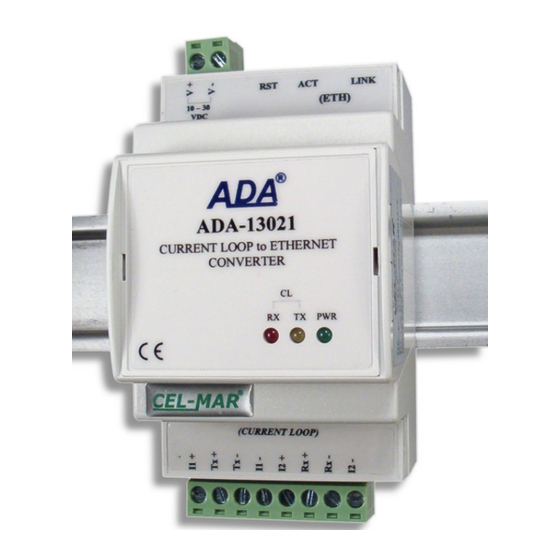
- Page 1 ADA-13021 User manual ADA-13021 ETHERNET to Current Loop converter Copyright © 2001-2020 CEL-MAR sp.j. io_ada-13021_v1.07_en...
-
Page 2: Table Of Contents
ADA-13021 Contents 1. GENERAL INFORMATION..................................4 1.1. WARRANTED INFORMATION..............................4 1.2. GENERAL CONDITIONS FOR SAFE USE........................... 4 1.3. CE LABEL...................................... 4 1.4. ENVIRONMENTAL PRESERVATION............................4 1.5. SERVICE AND MAINTENANCE..............................4 1.6. PACK CONTENTS..................................4 2. PRODUCT INFORMATION..................................4 2.1. PROPERTIES....................................4 2.2. - Page 3 ADA-13021 6.1. VIRTUAL PORT DRIVER INSTALLATION IN WINDOWS XP....................22 6.2. REALPORT CONFIGURATION IN WINDOWS XP........................22 7. FACTORY DEFAULT................................... 24 8. PROBLEMS......................................24 9. VERSIONS......................................24 10. SPECIFICATION....................................25...
-
Page 4: General Information
1.1. WARRANTED INFORMATION ADA-13021 converter is covered by a two year warranty from date of sale. In case of being damaged it will be repair or the damaged component will be replace. The warranty does not cover damage caused from improper use, materials consumption or any unauthorized changes. -
Page 5: Description
In the ETHERNET network converter can operate in Virtual Serial Port mode, TCP serial bridge mode, UDP serial bridge mode, TCP sockets, UDP sockets. The ADA-13021 converter transmits data via Current Loop interface with the baud rate 38,4kbps by the use of 2-pair of twisted-pair cable. The converter has screw terminal block for connection of Current Loop interface and power supply and RJ45 connector for Ethernet network connecting. -
Page 6: Current Loop Interface
Fig. 4. Isolation structure 3. INSTALLATION This chapter will show how to connect ADA-13021 to Current Loop bus, LAN/WAN network and power supply and how to use it. In the purpose of minimization of disruptions from environment is being recommended to: ●... -
Page 7: Assembling
3.2.1. CONNECTING TO NETWORK ADAPTER OF PC If there is not the switch or the HUB, it is possible to connect the ADA-13021 directly to a network adapter of PC using the cross-over cable (Table 2). This connection can be used for converter configuration. -
Page 8: Connection For Operating In Tcp & Udp Serial Bridge Mode
ADA-13021 Fig. 5 (above) and 6, 7 below show how correctly connect the ADA-13021 to LAN, WAN network or PC, to operating in virtual serial port mode (RealPort). For direct connection of the converter to PC network adapter, use the cross-over cable (see Table 2) and for connection by the use of switch or HUB use the straight cable (see Table 1). - Page 9 ADA-13021 Local network ETHERNET based on the switch ETHERNET Straight cable (Table 1) ADA-13021 ADA-13021 Device with Static IP address Static IP address Device with Current Loop Current Loop interface interface Current Loop Current Loop Fig. 8. The LAN connection to operating in the TCP/UDP serial bridge mode, one-to-one...
-
Page 10: Connection To Current Loop Devices
Receiver Rx - I2 - Power supply Vss+ Vss- Fig. 10. Example connection of device with passive transmitter and passive receiver to ADA-13021 3.3.2. CONNECTION TO DEVICE WITH ACTIVE TRANSMITTER & ACTIVE RECEIVER Current Loop ADA-13021 Device ETHERNET Current Loop... -
Page 11: Connection To Device With Active Transmitter & Passive Receiver
3.4. POWER SUPPLY CONNECTION The power supply to the ADA-13021 converter should be DC (regulated) from 10 V= to 30V=. Nominal power is typically 3W, e.g. HDR-15-24. Power cable from DC power supplies to device must not be longer than 3m. -
Page 12: Activation
ADAFinder is use for initial configuration of converter's network setting. Before running ADAFinder should be disabled the System FireWall! After running, the program is searching local network and if find ADA-13021, will add them to the list of available converters [Devices:] Fig.14. - Page 13 ADA-13021 Fig. 14. Base configuration network by the use ADAFinder software Fig. 15. ADAFinder configuration of IP network address...
-
Page 14: Configuration And Management By The Use Of Internet Browser
5.2.1. NETWORK CONFIGURATION To make a changes of default setting or new configuration of ADA-13021, select on left panel Configuration -> Network and then on right [IP Settings] (Fig.16) and make the selection: Obtain an IP address automatically using DHCP or Use the following IP address (in this option, enter IP Address of the converter, Subnet Mask, Default Gateway), press [Apply] for save. -
Page 15: Serial Port Configuration
Fig. 17. The web page for network setting of ADA-13021 5.2.2. SERIAL PORT CONFIGURATION The configuration of serial port of ADA-13021 converter includes: port description, setting of port profile (operating mode) and setting of serial transmission parameters (baud rate, data bits, parity, stop bits). -
Page 16: Realport (Virtual Port ) Configuration
Press [Apply] for save. After installation driver (RealPort) of virtual port COM (see chapter 6) in operating system, data sending by application to this port are transferred through WLAN/WAN to ADA-13021 converter and are present on his serial port. The driver RealPort installation is presented in chapter 6. -
Page 17: Enable Tcp Keep-Alive' Option Configuration
– Probe Count – the number of times TCP probes the connection to determine (scope 5 – 30 trials). 5.2.2.1.2.3. SERIAL PORT TRANSMISSION PARAMETERS CONFIGURATION For proper operation of ADA-13021 with device connected to his serial port (Current Loop), should be set the same transmission parameters for both devices. -
Page 18: Udp Client & Server Configuration In Case Of Slave Device
UDP server on e.g. 2101 port. Then select Automatically send serial data in section UDP Client Settings, this automatically send received data by the use UDP client service to the SLAVE device connected to LAN/WAN through e.g. ADA-13021 ADA-13020, ADA-13028L, ADA-13040MG, ADA-13110, ADA-14040, ADA-14040. -
Page 19: Serial Port Transmission Parameters Configuration
. 5.2.2.1.3.3. SERIAL PORT TRANSMISSION PARAMETERS CONFIGURATION For proper operation of ADA-13021 with device connected to his serial port (Current Loop), should be set the same transmission parameters for both devices. -
Page 20: Serial Port Transmission Parameters Configuration
On the configuration page Users are two sections: – Users – Configure Users The section Users allows to configure the method of login to ADA-13021. Selecting the option Enable user logins means that after enter the address http://<adres-ip-konwertera>/admin/administration.htm to internet browser, will open login window and will be necessary to enter user name and password. -
Page 21: Management
- Network – show statistics of ETHERNET interface for IP, TCP, UDP, ICM protocols. 5.2.6.6. REBOOT Section Reboot allows to make software reset of ADA-13021. Pressing [Reboot] will start rebooting of server during 1 min. 5.2.6.7. LOGOUT – ENDING MANAGEMENT AND CONFIGURATION After completion of the configuration or administration should be pressing Logout on left panel –... -
Page 22: Using Virtual Port Service [Realport]
8. Select IP address, MAC, DNS server for communication with virtual port driver. In the window [ Advanced Properties] click [ADA-13021] and then select [Network] (Fig. 30), and set the IP address, MAC Address or DNS name of the wireless serial server for communication with virtual port driver. - Page 23 ADA-13021 Fig. 29. Devices view on Windows XP Fig. 30. Example configuration of multi-port serial adapter...
-
Page 24: Factory Default
ADA-13021 - Electronics version: Standard Current Loop Voltage: Order example: 24VDC Product symbol: ADA-13021-1-2-1-2 12VDC (standard) 1 – standard electronics version, Current Loop Current: 2 – current loop voltage12VDC, 0 – 20 mA (standard) 1 – current loop current 0-20mA, 2 –... -
Page 25: Specification
ADA-13021 10. SPECIFICATION TECHNICAL DATA Transmission Parameters Net/ Interface ETHERNET Current Loop Connector RJ45 Screw terminal, wire max. Ø 2,5mm Max. Line length LAN up to 150 m Depend on baud rate, up to few kilometres Do 38,4 kbps (depend on current loop line Max. - Page 26 ADA-13021...
- Page 27 ADA-13021...
- Page 28 Thank you for purchasing CEL-MAR Company products. We hope that this user manual helped connect and start up the ADA-13021 converter. We also wish to inform you that we are a manufacturer of the widest selections of data communications products in the world such as: data transmission converters with interface RS232, RS485, RS422, USB, Current Loop, Fibre-Optic Converters and Ethernet or Wi-Fi.
Need help?
Do you have a question about the ADA-13021 and is the answer not in the manual?
Questions and answers