
Related Manuals for CEL-MAR ADA-1040D


Summary of Contents for CEL-MAR ADA-1040D
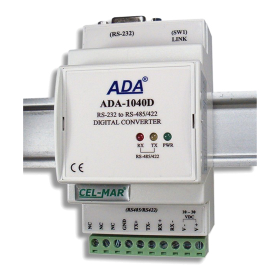
- Page 1 ADA-1040D User manual ADA-1040D RS-232 to RS-485(4W)/RS-422 digital converter Copyright © 2001-2020 CEL-MAR sp.j. io_ada-1040d_v1.11_en...
-
Page 2: Table Of Contents
ADA-1040D Contents 1. GENERAL INFORMATION..................................3 1.1. WARRANTED INFORMATION..............................3 1.2. GENERAL CONDITIONS FOR SAFE USE........................... 3 1.3. CE LABEL...................................... 3 1.4. ENVIRONMENTAL PRESERVATION............................3 1.5. SERVICE AND MAINTENANCE..............................3 1.6. PACK CONTENTS..................................3 2. PRODUCT INFORMATION..................................3 2.1. PROPERTIES....................................3 2.2. -
Page 3: General Information
1.1. WARRANTED INFORMATION ADA-1040D converter is covered by a two year warranty from date of sale. In case of being damaged it will be repair or the damaged component will be replace. The warranty does not cover damage caused from improper use, materials consumption or any unauthorized changes. -
Page 4: Description
2.2. DESCRIPTION ADA-1040D Digital Converter is used to extend RS232 ports of device using for communication signals: Tx, Rx, RTS, CTS, DTR, DSR. The converter receives data from RS-232 port and sends them via RS485(4W) / RS422 to second converter together with information about line condition of RS232 interface. -
Page 5: Isolation
ADA-1040D 2.3. ISOLATION Converter ADA-1040D has 2-way or 3-way galvanic isolation on the levels 1kV= or 3kV=, depend on version described in section VERSIONS. 2-WAY ISOLATION 3-WAY ISOLATION RS232 RS485/RS422 RS232 RS485/RS422 Power Supply Power Supply 10 - 30VDC 10 - 30VDC Fig 2. -
Page 6: Installation
ADA-1040D 4. INSTALLATION This chapter will show how to connect ADA-1040D to PC, RS485 & RS422 bus, and power supply and how to use it. To reduce disturbance from environment, it is recommended to: – use multipair type shielded cables, which shield can be connected to the earthing on one end of the cable, –... -
Page 7: Connection Of Devices With Rs232 Port - Dce Type (Modem)
4.2.2. CONNECTION OF DEVICES WITH RS232 PORT - DCE TYPE (MODEM) In purpose of connecting ADA-1040D to RS232 port type DCE (eg modem), should be used the RS232 cable, LINK type (available in CEL-MAR offer). Example connection is shown below. -
Page 8: Example Connection Of Converter As The Extension Port Rs232 Pc
Wrong polarization on terminals: Rx+, Rx-; change polarization. Rx LED lights continuously Wrong polarization on terminals: Tx+/A, Tx-/B; change polarization. No communication between ADA-1040D converters on RS485(4W)/RS422 bus (link break, no connection converters). Should be checked: LINK LED flashes with a - correctness of bus connection, frequency of 10 Hz. -
Page 9: Description Of Signalling Leds
RS-232 and RS485. First, should be set the number of COM port for communication with the converter, then readout the configuration from ADA-1040D memory using the button [Read converter configuration] and make the proper changes of each interfaces setting. -
Page 10: Configuration Of Rs485(4W)/Rs422 Interface
– control parity: no control, parity control, control of none parity, – number of stop bits : 1, 2, – frame spacing – range from 4 to 255 (silence time as frame's end) – not available for ADA-1040D, – data flow control - not available for ADA-1040D, Above transmission parameters can be different for both converters creating extension RS232. -
Page 11: Data Transmission Diagnostics
To check those counters press the button [Read transmission errors], and to delete (zeroing of counters in the memory of the converter) press [Delete transmission errors]. In case of parity errors or frame errors, should be checked the ADA-1040D converter's configuration and correctness connection of RS485 bus and RS232 device to converter ports. -
Page 12: Emergency Firmware Update
AFTER SUCCESSFUL UPDATING SET SW1 SW1-1 SW1-2 6.6. FACTORY DEFAULT In case of faulty functioning the ADA-1040D, can be restored the factory default setting. Set SW1 microswitch mode as in the table below SW1-1 SW1-2 Disconnect the power and after while connect again. After that, will be loaded the factory default setting. Parameters are as follows:... -
Page 13: Versions
Galvanic isolation: 1kV= 2-way 1kV= 3-way Order example: 3kV= 2-way Product Symbol: ADA-1040D-23-3 3kV= 3-way 23 - galvanic isolation: 1kV= 3-way, 3 - cover without inlets, plug-in screw terminal block Terminal & Terminal Cover: Cover without inlets, screw terminal block... - Page 14 ADA-1040D According to standards DIN EN50022, DIN EN43880 Location during work Free Mounting Rail mounting according to DIN35 standard / TS35.
- Page 15 ADA-1040D...
- Page 16 Thank you for purchasing CEL-MAR Company products. We hope that this user manual helped connect and start up the ADA-1040D converter. We also wish to inform that we are a manufacturer of the widest selections of data communications products in the world such as: data transmission converters with interface RS232, RS485, RS422, USB, Current Loop, Fibre-Optic Converters and Ethernet or Wi-Fi.
Need help?
Do you have a question about the ADA-1040D and is the answer not in the manual?
Questions and answers