
Related Manuals for CEL-MAR ADA-13020


Summary of Contents for CEL-MAR ADA-13020
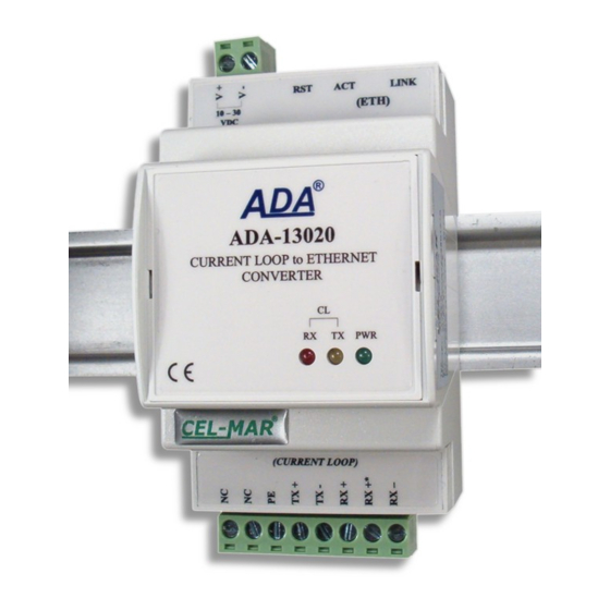
- Page 1 ADA-13020 User manual ADA-13020 ETHERNET to Current Loop Converter Copyright © 2001-2017 CEL-MAR sp.j. io_ada-13020_v1.14_en...
-
Page 2: Table Of Contents
ADA-13020 Contents 1. GENERAL INFORMATION..................................4 1.1. GUARANTEE INFORMATION................................ 4 1.2. GENERAL CONDITIONS FOR SAFE USE............................ 4 1.3. CE LABEL....................................... 4 1.4. ENVIRONMENTAL PRESERVATION............................4 1.5. SERVICE AND MAINTENANCE..............................4 1.6. PACK CONTENTS..................................4 2. PRODUCT INFORMATION..................................4 2.1. PROPERTIES....................................4 2.2. - Page 3 ADA-13020 6.2. REALPORT CONFIGURATION IN WINDOWS XP........................23 7. FACTORY DEFAULT.................................... 25 8. TROUBLESHOOTING................................... 25 9. VERSIONS......................................25 10. SPECIFICATION....................................26...
-
Page 4: General Information
1.1. GUARANTEE INFORMATION ADA-13020 converter is covered by a two year warranty from date of sale. In case of being damaged it will be repair or the damaged component will be replace. The warranty does not cover damage caused from improper use, materials consumption or any unauthorized changes. -
Page 5: Description
● Casing dimensions (W x D x H) 52,8mm x 62mm x 90mm. 2.2. DESCRIPTION ADA-13020 converter is used for data transmission between devices equipped with Current Loop interface via LAN/WAN network without interfering with data format. In the ETHERNET network converter can operate in Virtual Serial Port mode, TCP serial bridge mode, UDP serial bridge mode, TCP sockets, UDP sockets. -
Page 6: Ethernet Network Communication
2.4.2. CURRENT LOOP RECEIVER In ADA-13020 converter has been used passive RX receiver consisting of optoisolator (optical coupler) and protective elements. The receiver circuit has RX+, RX- terminals as well as the terminal marked as RX-*. In the circuit with RX-* terminal has been used additional resistor (1000 ohms or 560 ohms depend on the converter version) to reduce power in the case of connecting the receiver to transmitter which has NOT short circuit current limit to 20mA. -
Page 7: Isolation
3.2. ETHERNET NETWORK CONNECTION The ADA-13020 has to be connected to ETHERNET network by the use of the switch, the HUB or directly to the PC network adapter. The table below shows preparing of the straight cable for converter connection to switch or hub. -
Page 8: Connecting To Network Adapter Of Pc
3.2.1. CONNECTING TO NETWORK ADAPTER OF PC If there is not the switch or the HUB, it is possible to connect the ADA-13020 directly to a network adapter of PC using the cross-over cable (Table 2). This connection can be used for converter configuration. -
Page 9: Connection For Functioning In Tcp And Udp Serial Bridge Mode
Fig 7. Connection for operating in Real Port mode for WAN network 3.2.3. CONNECTION FOR FUNCTIONING IN TCP AND UDP SERIAL BRIDGE MODE Fig. 8 and 9 (below) show how correctly connect ADA-13020 converter to Ethernet network for functioning in TCP and UDP serial bridge mode. -
Page 10: Connection To Current Loop Interface Devices
ADA-13020 Local network ETHERNET built on the switch. ETHERNET Straight cable (Tabela 1) SLAVE Device with ADA-13020 Device with MASTER Device with Static IP address ADA-13020 Current Loop Current Loop Static IP address interface interface interface Current Loop Current Loop... -
Page 11: Connection To Device With Active Transmitter & Active Receiver
Fig 12. Example connection of device with passive transmitter/ passive receiver 3.4. EXAMPLE CONNECTION OF RS232 DEVICES TO CURRENT LOOP BUS By the use of ADA-13020 and ADA-1020, with Current Loop version as Active/Passive, I= 0-20 mA, can be created the Current Loop BUS like on the picture below. -
Page 12: Power Supply Connection
3.5. POWER SUPPLY CONNECTION The power supply to the ADA-13020 should be DC (regulated) from the scope 10 V= to 30V= and nominal power more than 3W e.g. DR-15-24. Power cable from DC power supplies to device must not be longer than 3m. Observe the polarity, connect positive (+) of DC power supplies to V+ and negative (-) end to V- terminal. -
Page 13: Activation
The ADAFinder is use for configuration of converter's network setting. Before running the ADAFinder should be disabled the System FireWall! After running, the program is searching local network and if find ADA-13020, will add them to the list of available converters [Devices:] Fig.14. - Page 14 ADA-13020 – Fig 14. Basic network configuration Fig 15. IP address setting...
-
Page 15: Configuration And Management By The Use Of Internet Browser
5.2.1. NETWORK SETTING CONFIGURATION To make changes of default setting or new configuration of ADA-13020, select on left panel Configuration -> Network and then on right [IP Settings] (Fig.16) and make the selection: Obtain an IP address automatically using DHCP or Use the following IP address (in this option, enter IP Address of the converter, Subnet Mask, Default Gateway), press [Apply] for save. -
Page 16: Serial Port Configuration
Fig 17. Page for network setting configuration of ADA-13020 converter 5.2.2. SERIAL PORT CONFIGURATION The configuration of serial port of the ADA-13020 converter includes: port description, setting of port profile (operating mode) and setting of serial transmission parameters (baud rate, data bits, parity, stop bits). -
Page 17: Realport (Virtual Port ) Configuration
5.2.2.1.2. TCP SOCKETS CONFIGURATION Choosing TCP Sockets, is configured the serial port of ADA-13020, for direct communication with PC by the use of TCP socked. Data sending by application to TCP socked are transferred through network to ADA-13020 converter and are present on his serial port. To save selected configuration, press the button [Apply]. -
Page 18: The 'Enable Tcp Keep-Alive' Option Configuration
ADA-13020 Fig 19. Configuration of TCP server For configuration of TCP Client Settings (Fig below), select Automatically establish TCP connections, connection between client and TCP server will be automatically. Then select Always connect and maintain connection option and in section Establish connection to the following network service enter IP address of device to which TCP client will send data, select service and enter port. -
Page 19: Serial Port Transmission Parameters Configuration
ADA-13020 5.2.2.1.2.3. SERIAL PORT TRANSMISSION PARAMETERS CONFIGURATION For proper operation of ADA-13020 with device connected to his Current Loop serial port, should be set the same transmission parameters for both devices. Select Basic Serial Settings and enter Baud Rate, Data Bits, Parity, Stop Bits, the same parameter like has device connected to the serial port of the converter. -
Page 20: Udp Client & Server Configuration In Case Of Slave Device
5.2.2.1.3.3. CONFIGURATION OF SERIAL PORT TRANSMISSION PARAMETERS For proper operation of ADA-13020 with device connected to his Current Loop serial port, should be set the same transmission parameters for both devices. -
Page 21: Serial Bridge Profile Configuration
After saving the Serial Bridge profile, will open section Serial Bridge Settings with operating parameters like on picture below. Select Initiate serial bridge to the following device option and enter IP address and 2101 Port of ADA-13020 with which to create the serial bridge over the network. -
Page 22: Management
- Network – show statistics of ETHERNET interface for IP, TCP, UDP, ICM protocols. 5.2.6.6. REBOOT Section Reboot allows making software reset of ADA-13020. Pressing [Reboot] will start rebooting of server during 1 min. 5.2.6.7. LOGOUT – ENDING MANAGEMENT AND CONFIGURATION After completion of the configuration or administration should be pressing Logout on left panel –... -
Page 23: Using Virtual Port Service [Realport]
8. Select IP address, MAC, DNS server for communication with virtual port driver. In the window [ Advanced Properties] click [ADA-13020] and then select [Network] (Fig. 25), and set the IP address, MAC Address or DNS name of the wireless serial server for communication with virtual port driver. - Page 24 ADA-13020 Fig 24. Device view on Windows XP Fig 25. Example configuration of multi-port serial adapter...
-
Page 25: Factory Default
I changed the configuration and the converter isn't functioning. 1. Enter in the Internet browser http://converter-ip-address, 2. Select the menu [Factory Default Settings] press [Restore]. 9. VERSIONS ADA-13020 - Electronic version: Basic Current Loop Voltage: 24VDC 12VDC Current Loop Type: ±... -
Page 26: Specification
ADA-13020 Order example: Product symbol: ADA-13020-1-1-1-2-3 1 – basic electronic version, 1 – current loop voltage 24VDC, 1 – current loop type ± 20mA, 2 – galvanic isolation 1kV=, 3 – cover without inlets, plug-in screw terminal block. 10. SPECIFICATION... - Page 27 ADA-13020...
- Page 28 Thank you for purchasing CEL-MAR Company products. We hope that this user manual helped connect and start up the ADA-13020 converter. We also wish to inform you that we are a manufacturer of the widest selections of data communications products in the world such as: data transmission converters with interface RS232, RS485, RS422, USB, Current Loop, Fibre-Optic Converters and Ethernet or Wi-Fi.
Need help?
Do you have a question about the ADA-13020 and is the answer not in the manual?
Questions and answers