
Related Manuals for ELTEX WOP-12ac-LR


Summary of Contents for ELTEX WOP-12ac-LR
- Page 1 Wireless access point WOP-12ac-LR User manual Firmware version 1.19.0 IP address: 192.168.1.10 Username: admin Password: password...
-
Page 2: Table Of Contents
WOP-12ac-LR. User manual Contents Introduction ..............................3 Annotation ..............................3 Symbols ............................... 3 Device description ............................4 Purpose ............................... 4 Device specification............................ 4 The device technical parameters....................... 5 Design ................................7 The device schematic structure......................... 8 Reset to the default settings ........................9 Delivery package ............................ -
Page 3: Introduction
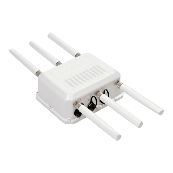
WOP-12ac-LR device is a Wi-Fi access point of Enterprise class. The device enclosed into hermetic case which allows to use the access point outdoor in different climatic conditions – at temperatures from –40 to +60°С. -
Page 4: Device Description
WOP-12ac-LR provides connection of up to 90 users. The device is used to organize wireless network for different climate conditions in the wide range of operation temperature and high humidity (parks, factories, stadium, etc.) and it is the perfect platform for organization of connection in cottage settlements and remote communities. -
Page 5: The Device Technical Parameters
2.3 The device technical parameters Table 1 – The device main technical parameters WAN interface parameters Number of ports 2 (3 for WOP-12ac-LR rev.D SFP/GPON) Connector SFP (for WOP-12ac-LR rev.D SFP/GPON), RJ-45, 10/100/1000, auto- sensing, BASE-T Wireless interface parameters Standards 802.11a/n/ac Frequency range... - Page 6 WOP-12ac-LR. User manual Control Remote control Web interface, Telnet, SSH, SNMP, EMS management system Firmware updating and configuring by DHCP Autoprovisioning Access restriction By password, by IP address General parameters Processor Broadcom BCM53016/BCM58522 NAND 128 MB NAND Flash 256 MB RAM DDR3 Power supply •...
-
Page 7: Design
WOP-12ac-LR. User manual 2.4 Design WOP-12ac-LR has an industrial design and metal case. Figure 1 shows the device side panel layout. Figure 1 – WOP-12ac-LR side panel layout Connectors and controls located on the device panels are listed in Table 2.4. Table 2 – Description of ports and controls... -
Page 8: The Device Schematic Structure
F> Functional button closed by hermetical screw 2.5 The device schematic structure Figure 2 shows WOP-12ac-LR schematic structure. Figure 2 – WOP-12ac-LR schematic structure • A1-A6– connectors for antennas; • Radio 1, Radio 2, Radio 3 – radio interfaces that performs reception and transmission of data in wireless networks;... -
Page 9: Reset To The Default Settings
WOP-12ac-LR. User manual 2.6 Reset to the default settings In order to reset the device to factory settings, press and hold the 'F' button within 15 seconds when the device in loaded state. Device will be rebooted automatically. DHCP client will be launched by default. If the address is not received via DHCP the device will have IP address — 192.168.1.10, subnet mask — 255.255.255.0 and User Name/... -
Page 10: Installation Order
WOP-12ac-LR. User manual 3 Installation order This section defines safety rules, installation recommendations, setup procedure and the device starting procedure. 3.1 Safety rules Do not open the device case. There are no user serviceable parts inside. It is required to cover unused antenna connectors by safety cover included in the device delivery package. -
Page 11: The Device Installation
Figure 3 – Channels allocation in range of 5 GHz when channel width is 20, 40 or 80 MHz When using the WOP-12ac-LR device, the following rules should be considered: When working with one radio interface, any of the available channels is selected. -
Page 12: Procedure Of Attaching Brackets To The Device
WOP-12ac-LR. User manual 3.4.1 Procedure of attaching brackets to the device Attach brackets (included in the delivery package) to the device before starting the device installation on mast/ pole or wall. Dust-protecting covers must be installed on the antenna connectors included in the device delivery package. -
Page 13: Algorithm Of Device Mounting To A Mast/Pole
WOP-12ac-LR. User manual 3.4.2 Algorithm of device mounting to a mast/pole Mount the bracket for attaching to a mast/pole: Figure 5 – Bracket for attaching to mast/pole a) Connect bracket, that will be attached to a mast/pole, to bracket, that will be attached to the device, as shown in Figure 5. - Page 14 WOP-12ac-LR. User manual 3. Attach the device to a mast/pole: Figure 7 – Mounting the device on a mast/pole a) Install the device on the top untwisted screws of a bracket attached to a mast/pole, see Figure 7. b) Install screws to the bottom bolthole, see Figure 7.
-
Page 15: Order For Wall-Mounting Brackets
WOP-12ac-LR. User manual 3.4.3 Order for wall-mounting brackets Fix the bracket (included in the delivery package) to the wall: Figure 8 – Attaching the bracket to a wall Figure 9 – Distances between mounting holes a) Figure 11 shows bracket allocation on the wall. Figure 9 shows distance between the boltholes. -
Page 16: Grounding Scheme Of The Device
WOP-12ac-LR. User manual 2. Fix the device on the wall Figure 10 – Wall-mounting the device a) Install the device on the top untwisted screws of a bracket attached to the wall, see Figure 13. b) Install screws in the bottom bolthole, see Figure 13. -
Page 17: Installing Antennas To Device
WOP-12ac-LR. User manual 3.4.5 Installing antennas to device After installing the device on the pipe rack and its grounding, you need to connect the antenna. As an example, Figure 12 shows the connection diagram of a sector antenna with double polarization. - Page 18 WOP-12ac-LR. User manual Figure 12 – Diagram of connecting the antenna to the device...
-
Page 19: Appendix А. Pin Array
WOP-12ac-LR. User manual 4 Appendix А. PIN ARRAY Power connector pin array Figure 13 – 48V power supply connector pin array RJ-45 connector pin array The next scheme is used for twisted-pair wiring. RJ-45 connector Side А: white orange;... - Page 20 WOP-12ac-LR. User manual Figure 14 – RJ45-DB9 console cable pin array...
-
Page 21: List Of Changes
WOP-12ac-LR. User manual 5 List of changes Document version Issue date Revisions Version 1.12 24.02.2020 Synchronization with firmware version 1.19.0 Version 1.11 01.10.2019 Synchronization with firmware version 1.18.1 Version 1.10 05.06.2019 Synchronization with firmware version 1.17.0 Version 1.9 12.02.2018 Synchronization with firmware version 1.16.0... -
Page 22: Technical Support
29 Okruzhnaya Str., Novosibirsk, Russian Federation, 630020 E-mail: techsupp@eltex-co.ru You are welcome to visit ELTEX official website to get the relevant technical documentation and software for ELTEX products or consult a Service Center Specialist on our technical forum. https://eltex-co.com/ https://eltex-co.com/support/downloads/...
Need help?
Do you have a question about the WOP-12ac-LR and is the answer not in the manual?
Questions and answers