
Related Manuals for Cypress PSoC 4 CY8CKIT-049-4 Series


Summary of Contents for Cypress PSoC 4 CY8CKIT-049-4 Series
- Page 1 CY8CKIT-049-4xxx ® PSoC 4 Prototyping Kit Guide Doc. #: 001-90711 Rev. *G Cypress Semiconductor 198 Champion Court San Jose, CA 95134-1709 Phone (USA): +1.800.858.1810 Phone (Intnl): +1.408.943.2600 http://www.cypress.com...
- Page 2 Cypress Source Code and derivative works for the sole purpose of creating custom software and or firmware in support of licensee product to be used only in conjunction with a Cypress integrated circuit as specified in the applicable agreement.
-
Page 3: Table Of Contents
Contents Safety Information 1. Introduction Kit Contents .........................7 Getting Started......................8 Additional Learning Resources..................8 1.3.1 PSoC Creator....................9 1.3.2 PSoC Creator Code Examples ..............10 1.3.3 PSoC Creator Help ..................11 1.3.4 Technical Support...................12 Document Conventions .....................12 2. Software Installation Before You Begin.......................13 CY8CKIT-049-41xx/CY8CKIT-049-42xx Software ............13 Install Software ......................14 Install Hardware......................14 Uninstall Software......................14... - Page 4 Contents 5.4.2 Entering Bootloader Mode from the Bootloadable Application ...... 51 6. USB-Serial Configuration USB-Serial Resources....................55 USB-Serial Configuration Utility................. 56 6.2.1 Connecting to a USB-Serial Device ............... 57 6.2.2 Configuring a Serial Port................58 6.2.3 Configuring GPIOs..................61 6.2.4 Additional Features of the USB-Serial Device ..........63 A.
-
Page 5: Safety Information
Safety Information Regulatory Compliance The CY8CKIT-049-4xxx Prototyping Kit is intended for use as a development platform for hardware or software in a laboratory environment. The board is an open system design, which does not include a shielded enclosure. This may cause interference to other electrical or electronic devices in close proximity. - Page 6 General Safety Instructions ESD Protection ESD can damage boards and associated components. Cypress recommends that you perform procedures only at an ESD workstation. If such a workstation is not available, use appropriate ESD protection by wearing an antistatic wrist strap attached to the chassis ground (any unpainted metal surface) on your board when handling parts.
-
Page 7: Introduction
This kit supports either 5 V or 3.3 V power supply voltages. The device can be programmed using the bootloader or the Cypress MiniProg3 programmer. The PSoC 4 Prototyping Kit supports boards based on the 4100 and 4200 device families, delivering a programmable platform for a wide range of embedded applications at a very low cost. -
Page 8: Getting Started
Appendix on page 65 provides the schematics, pin assignment, and bill of materials (BOM). Additional Learning Resources Cypress provides a wealth of data at www.cypress.com to help you to select the right PSoC device for your design, and to help you to quickly and effectively integrate the device into your design. For a... -
Page 9: Psoc Creator
Introduction 1.3.1 PSoC Creator PSoC Creator is a free Windows-based Integrated Design Environment (IDE). It enables concurrent hardware and firmware design of systems based on PSoC 3, PSoC 4, and PSoC 5LP. See Figure 1-2 – with PSoC Creator, you can: 1. -
Page 10: Psoc Creator Code Examples
Introduction 1.3.2 PSoC Creator Code Examples PSoC Creator includes a large number of code example projects. These projects are available from the PSoC Creator Start Page, as Figure 1-3 shows. Example projects can speed up your design process by starting you off with a complete design, instead of a blank page. -
Page 11: Psoc Creator Help
Introduction Figure 1-4. Code Example Projects, with Sample Code 1.3.3 PSoC Creator Help Visit the PSoC Creator home page to download the latest version of PSoC Creator. Then, launch PSoC Creator and navigate to the following items: Quick Start Guide: Choose Help > Documentation > Quick Start Guide. This guide gives you ■... -
Page 12: Technical Support
If you have any questions, our technical support team is happy to assist you. You can create a sup- port request on the Cypress Technical Support page. If you are in the United States, you can talk to our technical support team by calling our toll-free num- ber: +1-800-541-4736. -
Page 13: Software Installation
Before You Begin All Cypress software installations require administrator privileges, but these are not required to run the software after it is installed. Close any other Cypress software that is currently running before installing the kit software. Note: The kit contents are installed in the C:\Program Files\Cypress folder by default. If the Code examples are being run from the default install location, administrator privileges are required. -
Page 14: Install Software
There is no additional hardware installation required for this kit. Uninstall Software To uninstall the software, do one of the following: Go to Start > All Programs > Cypress > Cypress Update Manager > Cypress Update ■ Manager, and then select the Uninstall button corresponding to the kit software. -
Page 15: Open The "Psoc 4 Code" Code Example In Psoc Creator
Note: The code examples require administrator privileges if they are run directly from the default install location (C:\Program Files\Cypress). If you do not have administrator privileges, copy the Firmware folder from the default install location to any other location on your PC and use the files. - Page 16 Software Installation CY8CKIT-049-4xxx PSoC® 4 Prototyping Kit Guide, Doc. #: 001-90711 Rev. *G...
-
Page 17: Kit Operation
Kit Operation The PSoC 4 Prototyping Kit is simplistic in design and focuses on providing you with complete access to develop applications using the PSoC 4 device family. The development kit supports a number of onboard functions such as an LED, push button, through-hole connections, USB-Serial connectivity to the PC, and a breakable board design to separate the two target boards. -
Page 18: Cy8Ckit-049-4Xxx Usb Com Port
Kit Operation Figure 3-3. PSoC 4 Prototyping Kit Connected to the Computer CY8CKIT-049-4xxx USB COM Port When you connect the CY8CKIT-049-4xxx to the PC over a USB interface, it enumerates as a COM port device under the Device Manager window on the Windows OS. Often, the COM port number will be higher than any existing COM port value. -
Page 19: Programming A Cy8Ckit-049-4Xxx Project Using The Bootloader
Kit Operation Figure 3-6. Driver Software Installation Complete Note: The baud rate settings do not apply to the virtual COM port as the data transmission is taking place using the Full-Speed USB bus at 12 Mbps. However, because of the virtual COM port driver that sits between the PC and the USB-Serial device, the operating system will see the device as a normal serial port and you will be able to set the baud rate. - Page 20 Kit Operation 2. Open the SCB_Bootloader.cywrk workspace from Examples and Kits > Kits. Select CY8CKIT-049-41xx folder for CY8CKIT-049-41xx PSoC 4 Prototyping Kit and CY8CKIT-049-42xx folder for CY8CKIT-049-42xx PSoC 4 Prototyping Kit. 3. Select the folder where you want to save the project and click OK. Figure 3-7.
- Page 21 Kit Operation 4. Click on Build > Build All Projects. Note: The UART_Bootloader project is a dependency for the Bootloadable Blinking LED project. Hence, both example projects must be built by selecting Build > Build All Projects. 5. In the Workspace Explorer, right-click the Bootloadable Blinking LED project and select Set As Active Project.
- Page 22 Kit Operation 7. In the schematic view, right-click the Bootloadable component and select Configure. Figure 3-10. Configure the Bootloader Component CY8CKIT-049-4xxx PSoC® 4 Prototyping Kit Guide, Doc. #: 001-90711 Rev. *G...
- Page 23 Kit Operation 8. In the configuration window, select the Dependencies tab and click the Browse button to point to the HEX and ELF files present in the ‘Dependencies’ folder under project directory; click OK. The file paths (assuming the CY8CKIT-040-42xx) will appear as follows: <Project_Directory>\SCB_Bootloader\UART_Bootloader.cydsn\CortexM0\ ARM_GCC_484\Debug\UART_Bootloader.hex <Project_Directory>\SCB_Bootloader\UART_Bootloader.cydsn\CortexM0\...
- Page 24 Kit Operation 10.Connect the CY8CKIT-049-4xxx prototyping board to the PC. When connecting the kit to the port, depress the SW1 button as it is plugged in. You will notice that the blue LED begins to blink rapidly; this indicates that the PSoC 4 is in 'Boot- loader Mode' and is ready to be loaded with the latest firmware.
- Page 25 Kit Operation 12.Click Filters and select the Show UART Devices option from the Port Filters window and click OK. This lists all COM devices connected to the computer. Note: The PID of the Bootloader is F13B. You may enter this PID in the Port filters window to list only the Kit Bootloader.
-
Page 26: Usb-Uart Default Settings
The USB-Serial device is by default configured as a USB-UART device with the following specifications. The USB-UART settings can also be configured from the Cypress USB-Serial Configuration Utility. The default setting are as shown in bold in the table below. -
Page 27: Hardware
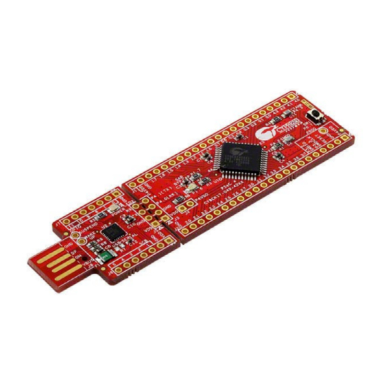
Hardware Board Details The PSoC 4 Prototyping Kit consists of the following blocks: PSoC 4 device ■ PSoC 4 header ports J1 and J2 ■ USB-Serial device ■ USB-Serial header ports J5 and J6 (GPIO) ■ UART connection J3 and J4 (SCB and GPIO) ■... -
Page 28: Theory Of Operation
Hardware Theory of Operation PSoC 4 is a new generation of programmable system-on-chip device from Cypress for embedded applications. It combines programmable analog, programmable digital logic, programmable I/O, and a high-performance ARM Cortex-M0 core. With PSoC 4, you can create the combination of peripher- als required to meet your application's specifications. -
Page 29: Board Separation (Snapping)
Hardware 4.3.1.1 Measure PSoC 4 Current Consumption You can measure the current consumption of the PSoC 4 device by using one of these methods: Method 1: 1. Separate the USB-Serial board by 'snapping' the perforated edge between the two boards. 2. - Page 30 Hardware 4.3.3.1 Functionality of the J1 and J2 Headers (PSoC 4) The main PSoC 4 board contains two dual-inline headers (J1 and J2). These headers are both 1×22-pin headers and include all of the I/O available on the PSoC 4 devices. These headers support all of the available ports, GND, VDD, and connections to passive elements and user-input devices.
- Page 31 Hardware Table 4-2. J2 Header Pin Details PSoC 4 GPIO Header (J2) Signal Description J2_01 Power J2_02 Ground J2_03 RESET Reset J2_04 P3.3 GPIO/SWDCLK J2_05 P3.2 GPIO/SWDIO J2_06 P3.7 GPIO J2_07 P3.6 GPIO J2_08 P3.5 GPIO J2_09 P3.4 GPIO J2_10 P3.3 GPIO/SWDCLK J2_11...
- Page 32 Hardware Table 4-3. Pin Details of J3 Header PSoC 4 to USB-Serial Header (J3) Signal Description J3_01 Power J3_02 Ground J3_03 P4.0 UART RX J3_04 P4.1 UART TX Table 4-4. Pin Details of J5 Header USB-Serial to PSoC 4 Header (J5) Signal Description J5_01...
-
Page 33: User And Passive Inputs
Hardware Table 4-5. Pin Details of J6 USB-Serial Comm/GPIO Header (J6) Signal Description J6_01 Power J6_02 Ground J6_03 S SEL Mode 0-6 J6_04 MISO/SCL Mode 0-6 J6_05 MOSI/SDA Mode 0-6 J6_06 SCLK Mode 0-6 J6_07 SCB.5/GPIO_7 Mode 0-6 Table 4-6. Pin Details of J7 USB-Serial GPIO Header (J7) Signal Description... - Page 34 Hardware Figure 4-9. Push Button Schematic 4.3.4.2 CY8CKIT-049-4xxx LEDs CY8CKIT-049-4xxx contains two LEDs: the amber LED, which indicates the board is power applied and the blue LED that is directly connected to the PSoC 4 device through the pin P1.6. The blue LED is also used to indicate the bootloader mode by rapidly blinking.
- Page 35 Hardware Figure 4-13. User LED Connection 4.3.4.3 System Capacitors The three capacitors on the CY8CKIT-049-4xxx prototyping kit enable proper development of ADC and CapSense code examples. These capacitors are the following: A SAR ADC bypass capacitor: Required for proper sampling at high frequencies, ■...
- Page 36 Hardware CY8CKIT-049-4xxx PSoC® 4 Prototyping Kit Guide, Doc. #: 001-90711 Rev. *G...
-
Page 37: Code Examples
Code Examples This section describes how to use the code example included with the kit and how to develop custom bootloadable code examples for new applications. For a list of all code examples available with PSoC Creator, visit the PSoC 3/4/5 Code Examples page. -
Page 38: Bootloadable Code Example
Code Examples Figure 5-1. UART Bootloader The Bootloader Base Project includes the source code in the main.c and the UART_Btld.c files, which support bootloading the PSoC 4 device. The source code is available for reference, but is not necessary to create bootloadable applications. Bootloadable Code Example The example in Programming a CY8CKIT-049-4xxx Project Using the Bootloader on page 19... -
Page 39: Creating A New Bootloadable Project
Code Examples Figure 5-2. Bootloadable Blinking LED Project Creating a New Bootloadable Project To create a new bootloadable project, do the following: 1. On the Start Page of PSoC Creator, click Create New Project. 2. On the New Project window, select an PSoC 4100/PSoC 4200 Design. 3. - Page 40 Code Examples 6. Click OK. Figure 5-3. Creating a New Bootloadable Project PSoC Creator generates a new project. CY8CKIT-049-4xxx PSoC® 4 Prototyping Kit Guide, Doc. #: 001-90711 Rev. *G...
- Page 41 Code Examples 7. Navigate to the schematic view to place your components (double-click on the .cysch file from the project in Workspace Explorer). Select the Page 1 tab in the schematic if it is not already selected. The key component that must be added is the Bootloadable component, which is used to generate the bootloadable application code.
-
Page 42: Converting A Non-Bootloadable Project To A Bootloadable Project
Converting a Non-bootloadable Project to a Bootloadable Project As part of PSoC Creator application notes and kits available at www.cypress.com, Cypress provides many code examples that you can work with. Most of these code examples do not include a boot- loader in the project and are not directly usable with the CY8CKIT-049 kit. -
Page 43: Pwmexample
Code Examples 5.4.1 PWMExample This example explains how to get the PWMExample project from the PSoC Creator code examples list into your workspace and target the CY8CKIT-049-4xxx development kits. 1. In PSoC Creator, click Find Example Project… under Start Page > Examples and Kits. Figure 5-7. - Page 44 Code Examples 3. You should now see all the examples supported by PSoC Creator for the selected family. In the Project Name field, enter ‘PWMExample’. Select the PWMExample project from the list dis- played and click Create New Workspace. Figure 5-9. PWMExample Project Lookup 4.
- Page 45 Code Examples 6. When the project opens in PSoC Creator, navigate to the Workspace Explorer window, right-click on the project, and select Build Settings. Figure 5-10. Accessing Build Settings 7. Because this project was originally set as a Normal Application Type, we need to change it to Bootloadable.
- Page 46 Code Examples 8. Double-click the TopDesign.cysch file from the Workspace Explorer to open the schematic view. Figure 5-12. Opening “TopDesign.cysch” 9. Drag and drop the Bootloadable component into the schematic window from the Component Catalog under System. Figure 5-13. Bootloadable Component in the Component Catalog CY8CKIT-049-4xxx PSoC®...
- Page 47 Code Examples 10.Double-click on the placed bootloadable component to configure the selections. Figure 5-14. General Tab Parameters 11. Click the Dependencies tab to select the .hex and .elf files from the UART Bootloader project included with the kit (<Install_Directory>\CY8CKIT-049-42xx\<version>\Firm- ware\SCB_Bootloader\ UART_Bootloader.cydsn\CortexM0\ARM_GCC_484\Debug\). This is done to point the bootloadable project to the bootloader running in the kit.
- Page 48 Code Examples 12.Because the project is not designed for the CY8CKIT-049 kit, you need to change the PWM out- put pin to the LED pin in CY8CKIT-049 (P1[6]). To do this, open PWMExample.cydwr from the Workspace Explorer. Figure 5-16. Opening “.cydwr” File 13.Select the LED_GREEN pin to P1[6] in the CY8CKIT-049 kit.
- Page 49 Code Examples 16.Open the Bootloader Host utility by selecting Tools > Bootloader Host from the PSoC Creator menu. Connect to the COM port and make your port configurations. Figure 5-19. Bootloader Host Tool 17.Click Filters…; configure it as shown in Figure 14 and then click OK. Figure 5-20.
- Page 50 Code Examples 18.Click the Open File button and navigate to the project’s .cyacd file available at the following path: <Project Directory>\PWMExample01\PWMExample01.cydsn\CortexM0\ARM_GCC_484\Debug Figure 5-21. Bootloader Host "cyacd" File Load Setting 19.Select the USB Serial Port (COMxx) corresponding to your kit and configure the settings, as shown in Figure 5-22.
-
Page 51: Entering Bootloader Mode From The Bootloadable Application
Code Examples 20.Click the Program button. When the firmware is programmed, observe that the LED moves from low intensity to higher intensity in steps of 100. You can change the BRIGHTNESS_DECREASE macro to modify the step size. Figure 5-23. Program Button in Bootloader Host 5.4.2 Entering Bootloader Mode from the Bootloadable Application To program the PSoC 4 device on the CY8CKIT-049 kit, you need to enter the bootloader mode... - Page 52 Code Examples 2. Double-click the placed component and configure the parameters as shown in Figure 5-25 click OK. Figure 5-25. Digital Input Pin Parameter Configuration 3. In the PWMExample01.cydwr file, select P0[7] as the pin connection for SW1. Figure 5-26. 'cydwr' Pin Settings CY8CKIT-049-4xxx PSoC®...
- Page 53 Code Examples 4. Open main.c file from the Workspace Explorer. Figure 5-27. Opening main.c CY8CKIT-049-4xxx PSoC® 4 Prototyping Kit Guide, Doc. #: 001-90711 Rev. *G...
- Page 54 Code Examples 5. Add the following code inside the infinite “for” loop. Note that you need to define a variable ‘uint8 swCounter’ in the beginning of the main loop. for(;;) /* Reset the software counter if SW1 is not pressed (Pulled high) if(SW1_Read()) swCounter = 0;...
-
Page 55: Usb-Serial Configuration
USB-Serial device on the CY8CKIT-049-4xxx kits. USB-Serial Resources Use the following links to access a wide variety of content that includes custom software, utilities, datasheets, and knowledge base articles. USB-Serial landing page: www.cypress.com/go/usbserial ■ Software and drivers: USB-Serial Software Development Kit (SDK) ■... -
Page 56: Usb-Serial Configuration Utility
USB-Serial device such as USB-UART configurations, USB- GPIO controls, and custom development using the USB-I2C and USB-SPI protocols. After you install the USB-Serial SDK, click Start > All Programs > Cypress > Cypress USB Serial > Cypress USB-Serial Configuration Utility to launch the USB-Serial Configuration Utility. -
Page 57: Connecting To A Usb-Serial Device
USB-Serial Configuration 6.2.1 Connecting to a USB-Serial Device 1. Connect the CY8CKIT-049-4xxx prototyping kit to the PC. 2. Open the USB-Serial Configuration Utility. 3. Select the Select Target tab. Figure 6-2. Selecting the Target in USB-Serial Configuration Utility The USB-Serial Configuration Utility will automatically detect that the USB-Serial Device has been connected to the PC and will display the device in the Select Device drop-down menu. -
Page 58: Configuring A Serial Port
USB-Serial Configuration 4. Click Connect. After connecting to the device, a new tab opens that displays the device marketing part number. Figure 6-3. Selecting the Connected Device 5. Select the new tab and begin configuring the device. 6.2.2 Configuring a Serial Port The USB-Serial device acts as a USB-UART bridge for the CY8CKIT-049-4xxx development kit. - Page 59 USB-Serial Configuration 3. Click Configure next to the UART mode select. The Configure UART Settings window appears, which displays the default settings for your UART-Serial device. Figure 6-5. Configuring UART Settings 4. Change the UART settings such as Baud Rate or Type by selecting the new values from the respective drop-down lists, and click OK.
- Page 60 USB-Serial Configuration 6. To reset the device from the Configuration Utility, navigate to the Device menu and select Reset Device. This initiates a reset to the device. Figure 6-8. Resetting the Device The utility will immediately detect that the device has been reconnected and display the Select Target tab.
-
Page 61: Configuring Gpios
USB-Serial Configuration 7. Connect to the device and navigate to the UART configuration window to see that the new config- uration has been set. In this example, the Baud Rate is changed from 115200 to 9600. Figure 6-10. Device UART Parameters Changed 6.2.3 Configuring GPIOs The USB-Serial device included in the CY8CKIT-049-4xxx Prototyping Kit also supports GPIO con-... - Page 62 USB-Serial Configuration 2. Navigate to the CapSense/BCD/GPIO tab. Figure 6-11. Device GPIO 3. Click Configure on the Unused GPIOs drive mode. This launches the GPIO configuration win- dow. This example shows how to change the output mode of the GPIO 08 pin to drive an output. You can connect the pin to the PSoC 4, an LED, or any external circuitry.
-
Page 63: Additional Features Of The Usb-Serial Device
Note: USB-UART works in the USB Communication Device Class (CDC), while all other configura- tion controls such as GPIO, SPI, and I2C use the Cypress vendor driver on the PC. Therefore, COM port tools such as PuTTY or HyperTerminal will only work for the UART bridge. You can use the C++ APIs to create scripts and tools included with the USB-Serial SDK to evaluate and control the other bridge options. - Page 64 USB-Serial Configuration CY8CKIT-049-4xxx PSoC® 4 Prototyping Kit Guide, Doc. #: 001-90711 Rev. *G...
-
Page 65: Appendix
Appendix CY8CKIT-049-4xxx Schematics CY8CKIT-049-4xxx PSoC® 4 Prototyping Kit Guide, Doc. #: 001-90711 Rev. *G... - Page 66 Figure A-1. CY8C4245AXI-483 (CY8CKIT-049-42XX only) CY8CKIT-049-4xxx PSoC® 4 Prototyping Kit Guide, Doc. #: 001-90711 Rev. *G...
- Page 67 Figure A-2. CY8C4125AXI-483 (CY8CKIT-049-41XX only) CY8CKIT-049-4xxx PSoC® 4 Prototyping Kit Guide, Doc. #: 001-90711 Rev. *G...
- Page 68 CY8CKIT-049-4xxx PSoC® 4 Prototyping Kit Guide, Doc. #: 001-90711 Rev. *G...
- Page 69 CY8CKIT-049-4xxx PSoC® 4 Prototyping Kit Guide, Doc. #: 001-90711 Rev. *G...
- Page 70 CY8CKIT-049-4xxx PSoC® 4 Prototyping Kit Guide, Doc. #: 001-90711 Rev. *G...
- Page 71 CY8CKIT-049-4xxx PSoC® 4 Prototyping Kit Guide, Doc. #: 001-90711 Rev. *G...
-
Page 72: Programming A Cy8Ckit-049-4Xxx Project Using Miniprog3
Programming a CY8CKIT-049-4xxx Project Using MiniProg3 To use MiniProg3 for programming, connect wires or a 5-pin 100-mil spaced header to the programming header on the CY8CKIT-049-4xxx board. The programming header is a 5-pin header indicated on the silkscreen and is labeled ‘PROG’. The suggested part numbers are Molex 22-05-3051 (right angled male header) and Molex 22-23-2051 (straight header). - Page 73 Figure A-4. Connecting CY8CKIT-049-4xxx to MiniProg3 using straight header Note: CY8CKIT-002 MiniProg3 is not part of the PSoC 4 Prototyping Kit contents and can be purchased from the Cypress Online Store. The following images show the pinout for MiniProg3 and the connections on CY8CKIT-049-4xxx.
- Page 74 Figure A-6. CY8CKIT-049-4xxx Connections for MiniProg3 The code examples described in this section show how to bootload new projects into PSoC 4 and create bootloader and bootloadable projects. To access the kit examples, download the examples from the kit web page. The initial example shows how to program the kit with just a bootloader using MiniProg3.
- Page 75 2. Open the SCB_Bootloader.cywrk workspace by choosing File > Open > Project/Workspace and navigating to the directory in which your project is present. Figure A-8. Opening the Project in PSoC Creator The workspace includes two sample projects linked in the Workspace Explorer - a bootloader project and a bootloadable project.
- Page 76 6. Select Debug > Program. Figure A-11. Programming the CY8CKIT-049-4xxx The Select Debug Target window opens. Figure A-12. Debug Target Window 7. Click Port Settings, set the connector to 5 pin, and then click OK. 8. Click Port Acquire to detect the target device, click Connect, and then click OK. PSoC Creator programs the target.
-
Page 77: Bill Of Materials
Table A-1. Bill of Materials Item Reference Value Description Mfr Name Mfr Part Number PCB, 92.13mm x 24.13mm, High Tg, Cypress Semi- ENIG finish, 2 layer, Color = RED, Silk = 600-60178-01 conductors WHITE C1,C3,C5,C7,C8, CAP CERAMIC 1.0UF 25V X5R 0603 1.0 uF... - Page 78 CY8CKIT-049-4xxx PSoC® 4 Prototyping Kit Guide, Doc. #: 001-90711 Rev. *G...
-
Page 79: Revision History
Revision History ® CY8CKIT-049-4xxx PSoC 4 Prototyping Kit Guide Revision History Document Title: CY8CKIT-049-4xxx PSoC® 4 Prototyping Kit Guide Document Number: 001-90711 Origin of Revision Issue Date Description of Change Change 02/03/2014 RKAD New kit guide 03/20/2014 RKAD Moved section 3.2.1 to appendix section A-2. 06/23/2014 RKAD Updated the title in the file properties. - Page 80 Revision History ® CY8CKIT-049-4xxx PSoC 4 Prototyping Kit Guide Revision History (continued) Document Title: CY8CKIT-049-4xxx PSoC® 4 Prototyping Kit Guide Document Number: 001-90711 Origin of Revision Issue Date Description of Change Change Updated Introduction chapter on page Updated “Additional Learning Resources” on page Updated description.
- Page 81 Updated Software Installation chapter on page Updated “Install Software” on page Updated description. Removed figure “The 'Cypress' icon”. Removed figure “USB-Serial Driver Installation window”. Removed figure “USB-Serial Driver installation - Finish page”. 03/19/2015 SASH Removed “Uninstall USB-Serial Drivers” on page 15.
- Page 82 Revision History CY8CKIT-049-4xxx PSoC® 4 Prototyping Kit Guide, Doc. #: 001-90711 Rev. *G...
- Page 83 Mouser Electronics Authorized Distributor Click to View Pricing, Inventory, Delivery & Lifecycle Information: Cypress Semiconductor CY8CKIT-049-42XX CY8CKIT-049-41XX...
Need help?
Do you have a question about the PSoC 4 CY8CKIT-049-4 Series and is the answer not in the manual?
Questions and answers