
Related Manuals for Cypress PSoC CY8CKIT-048


Summary of Contents for Cypress PSoC CY8CKIT-048
- Page 1 CY8CKIT-048 ® PSoC Analog Coprocessor Pioneer Kit Guide Doc. # 002-11190 Rev. *B Cypress Semiconductor 198 Champion Court San Jose, CA 95134-1709 www.cypress.com...
- Page 2 Cypress is not liable, in whole or in part, and you shall and hereby do release Cypress from any claim, damage, or other liability arising from or related to all Unintended Uses of Cypress products.
-
Page 3: Table Of Contents
Contents Safety Information 1. Introduction Kit Contents .........................6 Board Details .......................7 PSoC Creator ......................9 Getting Started......................12 Additional Learning Resources..................12 Technical Support......................13 Documentation Conventions..................13 Acronyms........................13 2. Software Installation Before You Begin.......................15 Install Software ......................15 Uninstall Software......................17 3. Kit Operation Theory of Operation....................18 Flexible Prototyping ....................32 KitProg2 Functions ....................34 4. -
Page 4: Safety Information
General Safety Instructions ESD Protection ESD can damage boards and associated components. Cypress recommends that the user perform procedures only at an ESD workstation. If an ESD workstation is not available, use appropriate ESD protection by wearing an antistatic wrist strap attached to a grounded metal object. -
Page 5: Introduction
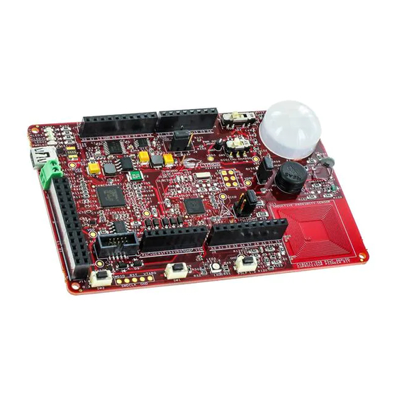
(ALS), and inductive proximity sensor (IPS). It has an RGB LED, two user-configurable push-button switches, one reset push-button switch, an onboard programmer/debugger with USB-UART/I2C bridge, and a Cypress F-RAM™. This kit supports operating voltages of 1.8 V, 3.0 V, 3.3 V, or 5 V. -
Page 6: Kit Contents
Quick Start Guide ■ Figure 1-2. Kit Contents Inspect the contents of the kit; if you find any part missing, contact your nearest Cypress sales office for help: www.cypress.com/support. PSoC Analog Coprocessor Pioneer Kit Guide, Doc. # 002-11190 Rev. *B... -
Page 7: Board Details
Introduction Board Details As shown in Figure 1-3, the PSoC Analog Coprocessor Pioneer Kit features five onboard sensors. The kit has two user buttons and an RGB LED. It also has a reset button, a power LED, and three status LEDs. The kit can be powered from three power sources: USB, coin cell, or an external power supply. - Page 8 Introduction Figure 1-4. PSoC Analog Coprocessor Pioneer Board Pinout Table 1-1. Jumpers/Switches Default Position Jumper/Switch Purpose Default Position System Power (VDD Voltage) Selection 1–2 (3.3V) Shunt Selection for Current Measurement 3–4 (NO SHUNT) 1–2 (SENSOR Humidity Sensor Calibration CONNECTED) VDD Source Selection Power Domain Monitor Selection DIGITAL PSoC Analog Coprocessor Pioneer Kit Guide, Doc.
-
Page 9: Psoc Creator
PSoC Creator also enables you to tap into an entire tool ecosystem with integrated compiler chains and production programmers for PSoC devices. For more information, visit www.cypress.com/psoccreator. PSoC Creator Code Examples PSoC Creator includes a large number of code examples. These examples are accessible from the... - Page 10 Introduction Create a new workspace for the code example or add to your existing workspace. This can speed ■ up your design process by starting you off with a complete, basic design. You can then adapt that design to your application. Figure 1-6.
- Page 11 Introduction Figure 1-7. Code Example Projects with Sample Code Kit Code Examples: You can access the installed kit code examples from the PSoC Creator Start Page. To access these examples, expand Kits under the section Examples and Kits; then, expand the specific kit to see the code examples.
-
Page 12: Getting Started
■ F-RAM, kit schematics, and the bill of materials (BOM). Additional Learning Resources Cypress provides a wealth of data at www.cypress.com to help you to select the right PSoC device for your design, and to help you to quickly and effectively integrate the device into your design. For a... -
Page 13: Technical Support
Learning from Peers: Visit www.cypress.com/forums to meet enthusiastic PSoC developers dis- ■ cussing the next-generation embedded systems on Cypress Developer Community Forums. Technical Support For assistance, visit Cypress Support or contact customer support at +1(800) 541-4736 Ext. 2 (in the USA) or +1 (408) 943-2600 Ext. - Page 14 Introduction Table 1-3. Acronyms Used in this Document (continued) Acronym Definition Field-effect Transistor GPIO General-Purpose Input/Output High Pass Filter Integrated Circuit ICSP In-Circuit Serial Programming IDAC Current DAC Integrated Design Environment Internet of Things Infrared Inter-Integrated Circuit Liquid Crystal Display Light-emitting Diode Low Pass Filter Least Significant Bit...
-
Page 15: Software Installation
Before You Begin To install Cypress software, you will require administrator privileges. However, this is not required to run software that is already installed. Before you install the kit software, close any other Cypress software that is currently running. Install Software Follow these steps to install the PSoC Analog Coprocessor Pioneer Kit software: 1. - Page 16 PSoC Creator 3.3 Component Pack 3 (CP3) or later: This software is available separately from www.cypress.com/psoccreator. b. PSoC Programmer 3.24.2 or later: This is installed as part of PSoC Creator installation or is available separately from www.cypress.com/programmer. PSoC Analog Coprocessor Pioneer Kit Guide, Doc. # 002-11190 Rev. *B...
-
Page 17: Uninstall Software
Uninstall Software The software can be uninstalled using one of the following methods: Go to Start > All Programs > Cypress > Cypress Update Manager and select the Uninstall ■ button that corresponds to the kit software. -
Page 18: Kit Operation
Kit Operation This chapter introduces you to the various features of the PSoC Analog Coprocessor Pioneer Kit, including the theory of operation and the onboard programming and debugging functionality. Theory of Operation Figure 3-1 shows a generic block diagram of a sensor-based system, which includes: 1. - Page 19 Kit Operation multi-voltage operation is achieved using a Cypress Power Management IC (PMIC). The operating voltage can be selected using a power selection jumper (J9). Figure 3-4 shows the block diagram of the power supply block. See Power Supply on page 31 for more details on this block.
- Page 20 5V Reset VIN VBUS (terminal block) Voltage 3.3V Arduino Compatible Power OR‐ing Resettable VDD Source Regulator Header (to shield) Diodes Fuse VBUS Selection (Cypress PMIC) Arduino Compatible Power 1.8/3.3V/5V (switch) Header (to baseboard) Shield (5V) Regulator control Coin cell Shield (5V) (ON/OFF) Regulator ON/OFF control Power Signal 3.1.1 PSoC Analog Coprocessor The PSoC Analog Coprocessor device has an extensive set of analog features and other resources.
- Page 21 Kit Operation Given below is a list of major features of the PSoC Analog Coprocessor device. Operating Range and Low-Power Modes Device operating voltage 1.71 V to 5.5 V ■ Sleep mode switches off clocks to the CPU. 3.1 mA typical current at 12 MHz. ■...
- Page 22 Kit Operation References can be routed to internal high-impedance analog resources: ADC, VDAC, ❐ comparator, and opamps. References can also be routed to a GPIO if buffered through an opamp. ❐ CapSense ■ Measures capacitance; can be used with capacitive sensors such as in liquid level or touch ❐...
- Page 23 Kit Operation 3.1.2 Analog Sensors Analog sensors generally come in five different types, depending on their output electrical signal: voltage, current, resistance, capacitance, or inductance. Each sensor type requires a specific AFE design as shown in Table 3-1. The PSoC Analog Coprocessor provides resources to build all of these AFEs, thus reducing the BOM cost and PCB size.
- Page 24 Kit Operation Most of the common PIR motion sensors have two or four sensing elements. These elements are arranged such that the voltage generated by one is subtracted by the other. This arrangement cancels the common signal and generates a voltage only when there is a difference in the incident infrared radiation level on the sensing elements.
- Page 25 Kit Operation Figure 3-9 shows the PSoC Creator schematic for interfacing a PIR motion sensor with the PSoC Analog Coprocessor. Figure 3-9. Interfacing PSoC Analog Coprocessor with PIR Motion Sensor The PIR motion sensor implementation on the PSoC Analog Coprocessor Pioneer Kit consists of five stages: a bias circuit for the PIR motion sensor, a first-stage amplifier, a high-pass filter (HPF), a second-stage amplifier, and an ADC.
- Page 26 Kit Operation 3.1.2.2 Interfacing with an Ambient Light Sensor An ambient light sensor (ALS) is a current sensor, which gives different current outputs based on the intensity of incident light on the sensor. The change in the current output is measured to detect the ambient light intensity.
- Page 27 Kit Operation 3.1.2.3 Interfacing with a Thermistor Temperature can be calculated by measuring the thermistor resistance. The PSoC Creator Thermis- tor Calculator Component simplifies the math-intensive resistance-to-temperature conversion. Figure 3-11 shows the PSoC Creator schematic for interfacing a thermistor with the PSoC Analog Coprocessor.
- Page 28 Kit Operation 3.1.2.4 Interfacing with an Inductive Proximity Sensor Inductive proximity sensing works on the principle of electromagnetic coupling between a sensor coil and the metal disk to be detected. When the metal disk enters the electromagnetic field induced by a sensor coil, some of the electromagnetic energy is transferred into the metal disk as shown in Figure 3-12.
- Page 29 Humidity can be measured by measuring the capacitance of a capacitive humidity sensor. A Cypress CapSense Component is used to measure the capacitance of the humidity sensor. The CapSense Component provides the best-in-class signal-to-noise ratio (SNR) (>5:1) for sensors with capacitance up to 200 pF.
- Page 30 Kit Operation Figure 3-14 shows the PSoC Creator schematic for interfacing a PSoC Analog Coprocessor with a humidity sensor. Figure 3-14. Interfacing PSoC Analog Coprocessor with a Humidity Sensor The PSoC Analog Coprocessor Pioneer Kit has a humidity sensor (HPP801A031) and a reference capacitor (C ) of 180 pF.
- Page 31 VIN or USB connector. The selection between 1.8 V, 3.3 V, and 5 V is made through a 4- pin jumper J9. A slider switch SW4 is used to select the power supply from the voltage regulator (Cypress PMIC - MB39C011APFT-G-BND-ERE1), USB or a 3-V coin cell. Table 3-2 lists the jumper J9 settings for different voltages.
-
Page 32: Flexible Prototyping
Kit Operation Flexible Prototyping PSoC Analog Coprocessor Pioneer Kit is footprint-compatible with Arduino Uno R3 shields and baseboards. It can interface with shields, or be used as a shield for any host processor board. It includes onboard KitProg2 programmer and debugger with ARM CMSIS-DAP. All the analog sensors on the PSoC Analog Coprocessor Pioneer Kit can be disconnected from the PSoC device or the header by removing the 0... - Page 33 Kit Operation Table 3-3. List of 0 Resistors Connecting PSoC Pins to Sensors and Headers (continued) 0 for 0 for Sensor Where on Sensor Circuit Header sensor header P3[4] Inductive proximity sensor Output of LPF R126 J2.5 R125 Series resistor of Inductive P0[2] Inductive proximity sensor R128...
-
Page 34: Kitprog2 Functions
KitProg2. KitProg2 is a multifunctional system, which includes a programmer, debugger, USB-I2C bridge, and a USB-UART bridge. A Cypress PSoC 5LP device is used to implement the KitProg2 functionality. KitProg2 is integrated in most PSoC development kits. For more details on the KitProg2 functionality, refer to the KitProg2 User Guide available in the kit installation directory: <Install_Directory>\CY8CKIT-048... - Page 35 Kit Operation 3.3.2 Programming Using PSoC Programmer PSoC Programmer (3.24.2 or later) can be used to program the existing .hex files into the PSoC Analog Coprocessor Pioneer Kit. Refer to the Programming Using PSoC Programmer section in KitProg2 User Guide for a detailed explanation on how to program using PSoC Programmer.
-
Page 36: Code Examples
Using the Kit Code Example Follow these steps to open and use the code examples. 1. Launch PSoC Creator from Start > All Programs > Cypress > PSoC Creator <version> > PSoC Creator <version>. 2. On the Start page, expand CY8CKIT-048 under Examples and Kits > Kits. A list of code... - Page 37 Code Examples 4. Build the code example by choosing Build > Build <Project Name>. After the build process is successful, a .hex file is generated. 5. To program the kit with the code example, connect the PSoC Analog Coprocessor to PC using USB cable as shown in Figure 3-17.
-
Page 38: Code Examples
Code Examples Code Examples Table 4-1 shows a list of code examples that can be used with this kit. Table 4-1. Code Examples Project Title/Description This code example demonstrates how to measure the voltage signal from a PIR sensor to detect the movement of an IR CE211301 PIR Motion Sensing emitting object. -
Page 39: Appendix
Appendix Schematics Refer to the schematics file in the following path: <Install_Directory>\CY8CKIT-048 PSoC Analog Coprocessor Pioneer Kit\1.0\ Hardware\CY8CKIT-048 Schematic.pdf Hardware Functional Description This section provides a detailed explanation of individual hardware blocks of the PSoC Analog Coprocessor Pioneer Kit. The details of PSoC Analog Coprocessor and KitProg2 are provided in “PSoC Analog Coprocessor”... - Page 40 Power LED PMEG2010AEB,115 The voltage regulator (U3, MB39C011APFT-G-BND-ERE1) from Cypress has two channels that provide different voltage levels. The regulator generates a constant 3.3 V on one channel. The other channel can be configured to generate 1.8 V, 3.3 V, or 5.0 V by setting the jumper J9 to desired position.
- Page 41 A.2.3 Protection Circuits A positive temperature coefficient (PTC) resettable fuse is connected to protect the computer's USB ports from shorts and over current (> 500 mA). ORing diodes are provided to prevent damage to components when the board is powered from different voltage sources at the same time. ESD pro- tection is provided on the USB connector.
- Page 42 A.2.5 Expansion Connectors A.2.5.1 Arduino-compatible Headers (J1 to J8, and J12) This kit has nine Arduino-compatible headers: J1, J2, J3, J4, J5, J6, J7, J8, and J12. You can develop applications based on the Arduino shield’s hardware. The J1 header contains I/O pins for reset, internal reference voltage (IOREF), and power supply lines.
- Page 43 P1[2] of the PSoC 5LP device. All the push buttons connect to ground on activation (active LOW). A.2.10 Cypress Ferroelectric RAM (F-RAM) The PSoC Analog Coprocessor Pioneer Kit contains an F-RAM device (FM24V10-G) that can be accessed through I2C lines P4 [0] and P4 [1] of the PSoC Analog Coprocessor. The F-RAM has a capacity of 1-Mbit (128 KB) with an I2C speed up to 3.4 MHz.
-
Page 44: Using The Fm24V10 F-Ram
Note: The 8-pin SOIC footprint provided for the F-RAM FM24V10 device on the PSoC Analog Pro- cessor Pioneer Kit is compatible with all I2C-based F-RAM devices from Cypress (FM24Vxx, FM24- CLxx, and CY15BxxxJ parts). F-RAM parts with more than 64 KB size support only four addresses (four devices of the same type on the same I2C bus);... - Page 45 A.3.2 High-Speed Mode (HS-mode) The FM24V10 supports a 3.4-MHz high-speed mode. A master code (00001XXXb) must be issued to place the device into high-speed mode. Communication between the master and the slave will then be enabled for speeds up to 3.4 MHz. A STOP condition will exit the Hs-mode. Single- and mul- tiple-byte reads and writes are supported.
- Page 46 A.3.3 Write/Read Operation The F-RAM datasheet includes details on how to perform a write/read operation with an F-RAM device. Figure A-7 Figure A-8 provide a snapshot of the write/read packet structure as a quick reference. Figure A-7. F-RAM Single-Byte and Multiple-Byte Write Packet Structure Figure A-8.
-
Page 47: Migrating Projects Across Different Pioneer Series Kits
I2C F-RAM devices with the PSoC Analog Coprocessor family. Migrating Projects Across Different Pioneer Series Kits Cypress Pioneer series kits are Arduino Uno-compatible and have some common onboard peripher- als such as RGB LED, CapSense and User Switch. However, the pin mapping in each of the boards is different due to differences in pin functions of the PSoC device used. - Page 48 A.4.1 Arduino Uno-Compatible Headers Table A-1. J1 Arduino-Compatible Header Pin Map Pioneer Series Kits Arduino CY8CKIT- CY8CKIT- CY8CKIT- CY8CKIT- CY8CKIT- CY8CKIT- CY8CKIT- 042-BLE V5.0 V5.0 V5.0 V5.0 V5.0 V5.0 V5.0 3.3V V3.3 V3.3 V3.3 V3.3 V3.3 V3.3 V3.3 RESET RESET RESET RESET RESET...
- Page 49 Table A-3. J3 Arduino-Compatible Header Pin Map Pioneer Series Kits Arduino CY8CKIT- CY8CKIT- CY8CKIT- CY8CKIT- CY8CKIT- CY8CKIT- CY8CKIT- 042-BLE P2[6] P1[4] P0[5] P0[2] P0[2] P0[3] P2[4] P3[6] P1[5] P0[4] P0[3] P0[3] P2[7] P1[7] P3[4] P1[6] P0[2] P2[7] P6[3] P0[7] P0[0] P3[0] P0[0] P6[0]...
- Page 50 Table A-5. RGB LED Pin Map Pioneer Series Kits Arduino CY8CKIT- CY8CKIT- CY8CKIT- CY8CKIT- CY8CKIT- CY8CKIT- CY8CKIT- 042-BLE P1[6] P3[2] P2[6] P0[6] P5[2] P3[4] P1[4] Green P0[2] P1[1] P3[6] P2[6] P5[3] P2[6] P2[6] Blue P0[3] P0[2] P3[7] P6[5] P5[4] P3[6] P1[6] Table A-6.
-
Page 51: Bill Of Materials
Bill of Materials BOM file is located in the following path in the kit software installation: <Install_Directory>\CY8CKIT-048 PSoC Analog Coprocessor Pioneer Kit\1.0 \Hardware\CY8CKIT-048 PCBA BOM.xlsx PSoC Analog Coprocessor Pioneer Kit Guide, Doc. # 002-11190 Rev. *B... -
Page 52: Revision History
Revision History ® CY8CKIT-048 PSoC Analog Coprocessor Pioneer Kit Guide Revision History Document Title: CY8CKIT-048 PSoC® Analog Coprocessor Pioneer Kit Guide Document Number: 002-11190 Origin of Revision Issue Date Description of Change Number Change 5185681 06/04/2016 DIMA Initial version of the kit guide. Updated Introduction chapter on page Updated... - Page 53 Index ® CY8CKIT-048 PSoC Analog Coprocessor Pioneer Kit Guide Revision History Document Title: CY8CKIT-048 PSoC® Analog Coprocessor Pioneer Kit Guide Document Number: 002-11190 Origin of Revision Issue Date Description of Change Number Change Updated Kit Operation chapter on page Updated “Theory of Operation”...
- Page 54 5302951 06/10/2016 SRDS Updated description. Updated “Push Buttons” on page Updated description. Updated “Cypress Ferroelectric RAM (F-RAM)” on page Updated description. Updated “External Crystals” on page Updated description. Updated “Using the FM24V10 F-RAM” on page Updated “Address Selection” on page Updated description.
Need help?
Do you have a question about the PSoC CY8CKIT-048 and is the answer not in the manual?
Questions and answers