
Related Manuals for D&R WEBSTATION


Summary of Contents for D&R WEBSTATION
- Page 1 MANUAL v1.02 D&R Electronica B.V., Rijnkade 15B, 1382GS Weesp, The Netherlands Phone: +31 (0)294-418014, Fax: +31 (0)294-416987, Website: http://www.d-r.nl, E-Mail: mail@d-r.nl W E B S T A T I O N M a n u a l P a g e 1...
-
Page 2: Table Of Contents
Contents SOFTWARE INSTALLATION ..........................5 webstation Control ............................. 5 webstation Meters ............................... 6 webstation Configuration Manager ........................7 webstation Voip ..............................7 Firmware Updatetool ............................8 INTRODUCTION MIXER UNIT ..........................9 MIC / LINE MODULES 1-3 ............................9 USB / LINE MODULES 4-7 ............................9 VOIP/ LINE MODULE 8 ............................ - Page 3 MIC ON ................................20 SET-UP ROUTINES MODULE 1-3 ........................21 10.1 SETTING UP AN INPUT CHANNEL ........................21 SET-UP ROUTINES MODULE 6 (VOIP) ......................22 WEBSTATION CONFIGURATION MANAGER ....................23 12.1 Introduction ..............................24 12.2 Connection & Setup ............................24 12.3 Communication ..............................
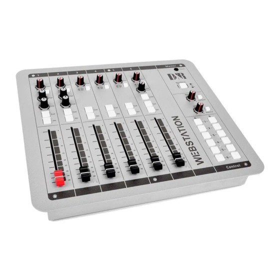
- Page 4 Thank you for choosing the d&r webstation mixer. The webstation was designed by radio broadcast professionals along with the d&r design team and is intended to be used 24 hours per day as an “on-air” mixer and/or a production console in the most demanding production room.
-
Page 5: Software Installation
1) Double click on Webstation Control vx.x.x.x – Setup.exe 2) Follow the installation instructions on the screen 3) If installation was successful you will see the Webstation Control icon in the taskbar 4) Richt-click on the icon and click on Settings... -
Page 6: Webstation Meters
Webstation Meters Webstation Meters is an application which shows metering levels and states of the Webstation console. The six buttons in the lower section of the meter screen indicate which source is selected and are also functioning as the Channel ON switch when clicked with a mouse (or touch screen) The NONSTOP indicator can also be used as remote control by clicking on 1) Double click on Webstation Meters vx.x.x.x –... -
Page 7: Webstation Configuration Manager
Press [READ] to read configuration settings from the console. Webstation Voip Webstation Voip is an application which let you answer or end calls from a voip application (only Skype supported at the moment) with the [CONNECT] button on module 8 of the Webstation console. -
Page 8: Firmware Updatetool
Firmware Updatetool Firmware Updatetool can be used to update the internal firmware of the Webstation console. The latest firmware can be downloaded from the D&R WIKI page: http://www.d-r.nl/wiki/dokuwiki/index.php 1) Double click on Firmware Updatetool vx.x – Setup.exe 2) Follow the installation instructions on the screen... -
Page 9: Introduction Mixer Unit
2 INTRODUCTION MIXER UNIT The Webstation mixer is designed as an 6 channel ON-AIR/Production mixer with all features you need to make professional radio productions. MIC / LINE MODULES 1-2 • 2x Professional extremely low noise balanced Mic pre-amps with 48 volt phantom powering on XLR. -
Page 10: Signal Flow
3 SIGNAL FLOW W E B S T A T I O N M a n u a l P a g e 10... -
Page 11: Webstation Backpanel
4 WEBSTATION BACKPANEL The back panel shows all the in and output connectors to interface with your other equipment. The first two of modules 1-2 MIC/LINE modules on the right have balanced XLR mic inputs with a mic insert for voice processing. -
Page 12: Mic / Line Input Modules 1-3
& cables allows for the quietest and high quality audio signals through- out your Webstation mixer. You can use standard balanced Mic cables available at any pro audio dealer or music store. The Webstation uses chassis-mount female XLR type Mic input connectors. -
Page 13: Input Connector
Now insert the stereo jack into the Webstation’s insert and connect the mono jack that produces a hum when the tip is touched by your finger (and the related channel fader is open) into the processors output. -
Page 14: Usb / Line Input Modules 3-4-5
A free downloadable tool can be found here http://minorshill.co.uk/pc2/testgen.html The return USB signal coming from the PC is fixed but can be adjusted with the webstation’s module gain controls. W E B S T A T I O N M a n u a l P a g e 14... -
Page 15: Setting Up The Modules
SETTING UP THE MODULES In order to set up a connection between your computer and the Webstation-USB mixer, only use the USB cable that is part of the shipment. When connecting the Webstation to your computer, the computer (PC or Mac) will recognize the Webstation as new hardware and will establish a connection to any audio programs needing audio hardware. -
Page 16: Voip / Line Input Module 6
4-wire audio circuits and standard 2 wire telephone lines. VoIP CHANNEL In the Webstation we have built in an interface that lets you connect to the Internet community by way of (for instance) Skype. Skype is freely available communication software that can be used to call and receive calls of your listeners to your broadcast station. -
Page 17: Fader
+10dB fader gain and see the -10dB (10) position as your unity gain position. 7.10 INPUT CONNECTORS On the back of the WEBSTATION VoIP module you find four connectors. Two unbalanced stereo line RCA Cinch connectors for connecting CD players, iPods, or any play-back devices as long as they are line level equipment. -
Page 18: Master Section
The green area of the LEDbar is the safe area and occasionally a red led on is no problem. The out- put level of your Webstation is designed to be 0dBu (775mV) (“0” VU) when the 0 green LED is on. NONSTOP The Non Stop switch is a very convenient function when you want to use your mixer while you are NON STOP on-air. -
Page 19: Metering
METERING Part of the total Webstation package is a software meter application and clock as seen below. All data is transported over the single USB 2.0 connection. An accurate clock time is taken from the local PC. The left stereo meter always shows the Master output, the right stereo meter shows the CRM output level following every signal selected by the CUE switches. -
Page 20: Master Backpanel Connectors
9 MASTER BACKPANEL CONNECTORS The master connector panel houses 12 RCA/Cinch connectors, 2 jack sockets, 3 male XLR connectors and 2x USB connector. There is one power supply connectors. From left to right we will describe the functions and features of the master connector panel as seen below in detail. -
Page 21: Set-Up Routines Module 1-3
Use the input gain for regular gain adjustments to create a convenient gain range to work with. Be carefully not to place the Webstation near heavy power transformers such as in power amps. Although the Webstation is constructed using a thick metal frame, this could cause hum. -
Page 22: Set-Up Routines Module 6 (Voip)
SET-UP ROUTINES MODULE 6 (VoIP) If you have already connected the USB cable for your play-out software, the VoIP connection is also available. Install for instance SKYPE on you PC and set up an account according to the instructions of the SKYPE software. -
Page 23: Webstation Configuration Manager
12 WEBSTATION CONFIGURATION MANAGER Configuration Manager User Manual VERSION 1.0.790.0 D&R Electronica B.V., Rijnkade 15B, 1382GS Weesp, The Netherlands Phone: +31 (0)294-418014, Fax: +31 (0)294-416987, Website: http://www.d-r.nl, E-Mail: mail@d-r.nl W E B S T A T I O N M a n u a l P a g e 23... -
Page 24: Introduction
Pressing Options->Communication from the menu bar will open the communication settings window. 12.3.1 Remote Host In the Remote Host field the IP address of the main PC needs to be specified. For running the Webstation Configuration Manager on the main PC one can use the 127.0.0.1 (localhost) IP address. -
Page 25: Module Settings
Apply entire configuration of the selected module to all other modules. 12.4.1 Power ON Active The Webstation console contains ON-switches to activate a specific module. If ON Active in the Power section is enabled the module will be active when powering the console. Using this function while a power outage occurs prevents silence on air if no person is in the studio to (re-)activate the module. -
Page 26: Switch Colours
12.4.4 Switch Colors In the Switch Colors section the colors of the ON and CUE switches can be configured to be OFF, RED, or GREEN depending on the state of the switch-function. It is up to the user to define a suitable color for a corresponding state. ON states: •... -
Page 27: Master Settings
12.5.1 Silence Detection The Webstation console is equipped with a software silence detection unit which is used to monitor the program buss (left, right , stereo) in the event of the signal going below the threshold (-40...0dB) after a given interval. In this situation the unit will go into ALARM state and switches the nonstop source to the master output. -
Page 28: Read Write Configuration From/To Console
12.6 Read/Write Configuration from/to console To read the configuration from the console into the Webstation Configuration Manager you need to press the ‘READ’ button. After the configuration has been read the firmware field shows the current firmware in the console after the read command. -
Page 29: Webstation Meters
13 WEBSTATION METERS Meters User Manual VERSION 1.1.205.0 D&R Electronica B.V., Rijnkade 15B, 1382GS Weesp, The Netherlands Phone: +31 (0)294-418014, Fax: +31 (0)294-416987, Website: http://www.d-r.nl, E-Mail: mail@d-r.nl W E B S T A T I O N M a n u a l P a g e 29... -
Page 30: Introduction
13.1 Introduction Webstation Meters is a software tool that lets you as a user monitor and control the Webstation console in an intuitive and user friendly manner. This manual describes the features Webstation Meters contains and how to setup and use the application. -
Page 31: Settings
Below the D&R logo the online indicator is located. This indicator will become green (online) when receiving metering data. Make sure the Webstation Control application is running on the main PC in order to provide the metering data to Webstation Meters. -
Page 32: On Switch
NONE, RED, GREEN. It is up to the user to determine which color represent a particular state. The icons in Webstation Meters can be seen as duplicates of the ON switches and can therefore behave as remote of the hard- ware switches. -
Page 33: Understanding Internet Radio
14 UNDERSTANDING INTERNET RADIO One of the key features of the Webstation is that you can set up your own Internet radio station from your home or office and have your friends listen to your broadcasts, be it music, talkshows, political, or religious programming. -
Page 34: Technical Specifications
15 TECHNICAL SPECIFICATIONS 15.1 SPECIFICATIONS INPUTS. : Mic inputs : XLR connector balanced impedance 2 kOhm. : Pin 1 = ground. : Pin 2 = hot (in phase). : Pin 3 = cold (out of phase). : +48 volt Phantom power : bal, 2 kOhm, XLR. -
Page 35: Dimensions
15.3 SUMMARY We hope this manual has given you sufficient information to use this new Webstation mixer in your studio. If you require more info please contact your local dealer or send us an email at mail@d-r.nl and we will answer your email within 24 hours during weekdays. -
Page 36: Electromagnetic Compatibility
: D&R Electronica b.v. Address manufacturer : Rijnkade 15B, : 1382 GS Weesp : The Netherlands declares that this product Name product : webstation Model number : n.a. Product options installed : none passed the following product specifications Safety : IEC 60065 (7th ed. 2001) - Page 37 T h e p l a c e w h e r e a l l m i x e r s a r e d e s i g n e d a n d b u i l d D&R Electronica B.V., Rijnkade 15B, 1382GS Weesp, The Netherlands Phone: +31 (0)294-418014, Fax: +31 (0)294-416987, Website: http://www.d-r.nl, E-Mail: mail@d-r.nl...
- Page 38 W E B S T A T I O N M a n u a l P a g e 38...
Need help?
Do you have a question about the WEBSTATION and is the answer not in the manual?
Questions and answers