Advertisement
Quick Links
Advertisement

Subscribe to Our Youtube Channel
Related Manuals for D&R AIRMATE-12


Summary of Contents for D&R AIRMATE-12
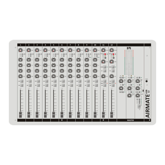
- Page 1 AIRMATE-USB MANUAL V 2.22 smd (Studio remote)
- Page 2 Dear Customer, Thank you for choosing the D&R AIRMATE-8-USB or AIRMATE-12-USB version mixer. The AIRMATE-USB was designed by Radio Broadcast professionals along with the D&R design team and is intended to be used 24 hours per day as an “On-Air” mixer and/or a production console in the most demanding production room.
- Page 3 1. INTRODUCTION The AIRMATE-USB has Four types of modules to choose from Triple Input Modules (positions 1-4/8) have the following features • Professional low noise balanced Mic pre-amp with 48 volt phantom powering. • Two pairs of line inputs with optional R.I.A.A. equalized pre-amp on line-B for turntables. •...
- Page 4 Below the AUX SEND is the stereo CUE switch (Pre Fade Listening), this switch allows you to check the signal be- fore you raise your channel fader up and mix it with other signals in the mixer. The ON switch is used to activate the module and generate a start sig- nal for turntables, CD players, and jingle or cart machines.
- Page 5 If you are going to make a cable yourselves, do it like this. Connect the tip from the stereo cable to the tip of one of the mono jacks and the ring of the stereo cable to the tip of the other mono jack. Now insert the stereo jack into the Airmate’s insert and connect the mono jack that produces a hum when the tip is touched by your finger (and the related channel fader is open) into the processors output.
- Page 6 SPECIAL OPTIONS FOR MODULES 1 - 4/8 Located on the input channel circuit boards are several jumpers that can be changed to enable different configura- tions of the channel settings. If changes are required, we advise you to contact your local dealer to have these changes performed.
- Page 7 USB-LINE MODULES 5/9 AND 6/10 CONNECTORS, CONTROLS, & FUNCTIONS * Low noise balanced Mic pre-amp with 48 volt phantom powering. * One pair stereo line inputs (left & right) * One USB connector (stereo in & out) * Gain control * Three band equalizer * Stereo CUE switch for pre fade listening * Start (ON) switch...
- Page 8 FADER Final control of the channel is the 100mm long throw K-Alps stereo channel fader with integrated fader start switch. The channel fader sends the amount of signal from the associated channel to the master mix buss. At the beginning of the fader movement you will feel an internally built in start switch that is activated when you bring up the fader.
- Page 9 4. SETTING UP THE USB MODULES Above pictured you see a section of the USB pcb where you can decide which output sig- nal is sent to the USB connector. The default setting is a post master stereo fader signal that is sent to the USB connector. You can change this by moving both yellow jumpers to the mid positions, now you have a pre-fader signal going to your PC.
- Page 10 5. SETTING UP THE USB MODULES Previous discussions about modules 1 thru 4/8 is also applicable for modules 5/9 and 6/10 except in these mod- ules line B is replaced by a USB interface circuit and connector. In order to set up a connection between your computer and AIRMATE-USB mixer, use a standard USB cable from any local computer shop.
- Page 11 Quicktime Streaming Server Apple.com says: “Whether you are looking to add streaming media to your web site, deliver distance learning or provide rich content for your mobile subscribers, Mac OS X Server has all of the tools you need. QuickTime Streaming Server lets you deliver live or prerecorded content in real time over the Internet.”...
- Page 12 TELCO-LINE MODULE 7/11 and 8/12 CONNECTORS, CONTROLS, & FUNCTIONS Input modules 7/11 & 8/12 have integrated Hybrid circuitry with built in high quality Telephone Hybrids as well as stereo line inputs in case only one Hybrid is needed. Highlights are: * High quality Telephone Hybrid circuit to directly connect to phone lines * Stereo line input * Gain control...
- Page 13 TALKBACK By pushing the TB switch on the Hybrid module, the internal talkback microphone is activated and allows you to talk to the caller without being ON-Air. AUX SEND Below the TB switch is the stereo Aux send that can be set to send stereo source signals pre or post fader (pre or post jumper settings on the circuit board).
- Page 14 SPECIAL AVAILABLE OPTIONS IN YOUR AIRMATE-TELCO MODULE On the input PCB of your AIRMATE-USB module there are several jumpers that can be changed to enable different configurations of the channel settings. This should be done by a D&R dealer or service center. The following 4 jumper settings can be changed to adjust the Airmate-USB Telco modules to your needs.
- Page 15 VoIP-LINE MODULE 7/11 and/or 8/12, CONNECTORS, CONTROLS, & FUNCTIONS Input module 7/11 and/or 8/12 are dedicated Voice over IP Telephone module and also have a stereo line input in case a classisc Hybrid is needed. Highlights are: * High quality Telephone Hybrid circuit to directly connect to the Internet. * Stereo line input.
- Page 16 RING (LED) This LED lights to alert you when a call comes in. You can also connect a warning light to the START jack to be visually informed that a call comes in (when you wear headphones). The ON switch is used to activate the module. This switch sends out a momentary pulse (de- fault) or switches permanently (continuously) between tip and ring of the Start connector on the back of the console.
- Page 17 Wireless Phone Channel (WiFi)-HYBRID/LINE MODULE 7/11 and/or 8/12, CONNECTORS, CONTROLS, & FUNCTIONS Input module 7/11 and/or 8/12 can be populated with a wireless Phone Hybrid module with line input. HIGHLIGHTS • High quality Telephone Hybrid circuit to directly connect to a phone •...
- Page 18 With this level control the outgoing signal from the mixer is sent to the caller via the Hybrid. This is for both the Hybrid and the Stereo Line input (when selected). This Hybrid gets it send signal from the cleanfeed output on the back of the console.
- Page 19 8. MASTER SECTION The AIRMATE-USB master section houses all the controls for the mix buss faders and master controls for Aux re- turn, 2-Track play-back, and master outputs. Individual functions are described below. LEDBAR METERS The master section has two high-res 21 segment LEDbar meters with VU meter Ballistics. Depending on which switch is pressed (Cue on channels, AUX SEND master, AUX RET, 2 TRACK, etc.), the master meters will allow the reading of all input and outgoing signals.
- Page 20 PHONES The phones output (located on the front panel) automatically switches between main mix outs and QUE from any input modules or on the Master section. Normally the left/right output is heard until a Cue switch is activated from anywhere in the console. Pressing a CUE switch, you will hear the associated signal rather than the left/right signal in the PHONES.
- Page 21 MASTER CONNECTORS The master connector panel houses 12 RCA Cinch connectors, 2 jack sockets, and 2 male XLR connectors. The electrical mains connector with integrated fuse holder is located in this section. A ground terminal completes the back panel connector section. TAPE OUTPUTS The tape output connectors are left and right outputs for connecting to the inputs of a stereo audio recorder or any other analog or digital device.
- Page 22 AUX RETURN The Aux return connectors are controlled by the Aux return control on the master section. The signal is connected directly to the master main mix busses. You can connect reverb returns or other stereo signals without using any input modules.
- Page 23 OPTIONAL MASTER AES/EBU XLR CONNECTORS If you have chosen to order digital outputs on your mixer the master AES/EBU XLR’s will be your digital in and out- puts to go fully digital to the transmitter or other broadcast devices connected to the AIRMATE-USB. As you can see in the picture below there are 2x 3 pin male XLR connectors, normally providing you with ground compensated balanced analog outputs that give the main program stereo signal, but now these are converted into a balanced digital AES/EBU standardized output signal (XLRE male) and...
- Page 24 OPTIONAL MASTER AES/EBU XLR CONNECTORS Below you see one of the master boards with the digital pcb mounted. On the left side of this small pcb you see jumpers. Now they are jumpered as default that the digital input signal is NOT routed to the 2 Track cinch connectors.
- Page 25 10. SET-UP ROUTINES MODULE 1-4/8 - Connect a power-amp, recorder, or transmitter to the left/right outputs. - Connect a high impedance headphone to the “phones” jack socket on the master section. - Connect the microphones as described. - Now, connect turntables, CD players, and jingle machines. - If more than 2 Telephone Hybrids are needed, you can connect another Hybrid to the Clean feed output.
- Page 26 12. SETTING UP THE TELCO MODULES Connect the two wires of the telephone line’s wall unit to the RJ-11 connector labeled wall (LINE) and connect the telephone appliance itself to the RJ-11 connector labeled PHONE. Note that to originate calls, a local phone must be connected to the Airmate-USB.
- Page 27 13. SUMMERY We hope this manual has given you sufficient information to use this new AIRMATE-USB mixer to the extreme specs it was designed to deliver. If you require more info please contact your local dealer or send us an email at mail@d-r.nl and we will answer your email within 24 hours during weekdays.
- Page 28 14. TECHNICAL SPECIFICATIONS MIC INPUTS XLR connector balanced impedance 2 kOhm. Sensitivity -60dBu. Pin 1 = ground. Pin 2 = hot (in phase). Pin 3 = cold (out of phase). +48 volt Phantom power (via jumper) INSERT Stereo jack. Tip=Input (connect to output of signal processor) Ring=Output (connect to input of signal processor) Ground=shield LINE A/B...
- Page 29 15. TECHNICAL SPECIFICATIONS INPUTS Mic input balanced 2 kOhm. Plus 48volt phantom Mic noise -122 dBr (A-weighted). Sensitivity: -70dB min, 0dB maximum. Line inputs: unbalanced, 10kOhm, Cinch gain range 40dB. Phono inputs: unbalanced, 47kOhm, 1-10 mV. 2 Track return: -10dBv at 10kOhm. Aux return: -10dBv at 10kOhm.
- Page 30 ELECTROMAGNETIC COMPATIBILITY This unit conforms to the Product Specifications noted on the Declaration of Conformity. Operation is subject to the following two conditions: This device may not cause harmful interference • This device must accept any interference received, including interference that may cause unde- •...
Need help?
Do you have a question about the AIRMATE-12 and is the answer not in the manual?
Questions and answers