
Related Manuals for D&R AXUM


Summary of Contents for D&R AXUM
- Page 1 DIGITAL AUDIO MIXING SYSTEM A·X·U·M User Manual D&R Electronica Weesp BV Rijnkade 15B 1382GS Weesp The Netherlands Phone: +31 (0)294-418014 Fax: +31 (0)294-416987 Website: http://www.d-r.nl Version 2.5 - 2011-01-28 E-mail: info@d-r.nl...
-
Page 2: Mambanet Example
We are confident that you will be using the AXUM for many years to come, and wish you lots of success in your business. And… please take some time to read this manual first to avoid unnecessary questions to yourself and to us. -
Page 3: Table Of Contents
GPO Active-state AVAILABLE I/O RACK CARDS 10.1 INPUT CARD 10.2 INE INPUT CARD 10.3 SRC) IGITAL IN OUTPUT CARD OPTIONAL 10.4 INE OUTPUT CARD 10.5 OUTPUT CARD AXUM from D&R - Phone: +31 294 418014 - E-Mail: info@d-r.nl - 3 -... - Page 4 19.2 HANGE PASSWORD 19.3 PLOAD LOGO APPENDIX C – ENGINE FUNCTIONS 20.1 ODULES 20.2 USSES 20.3 ONITOR BUSSES 20.4 ONSOLE 20.5 LOBAL 20.6 OURCES 20.7 ESTINATIONS AXUM from D&R - Phone: +31 294 418014 - E-Mail: info@d-r.nl - 4 -...
-
Page 5: Package Contents
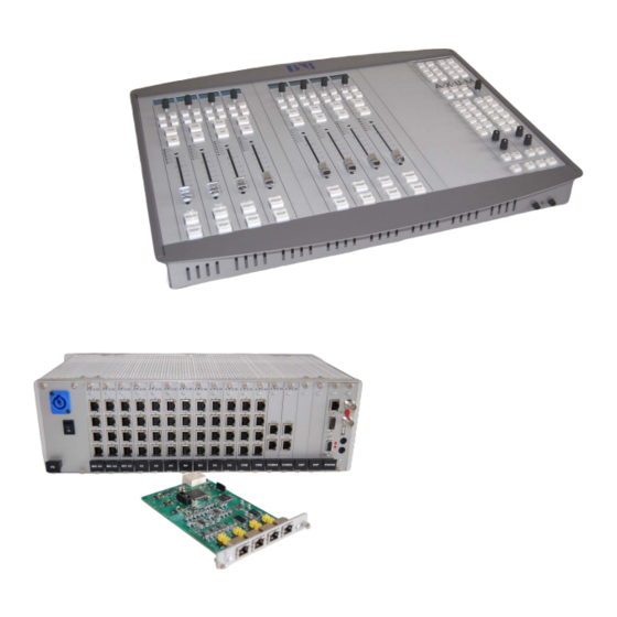
A·X·U·M User Manual Version 2.5 - 2011-01-28 2 Package Contents The AXUM package comes normally with the following parts inside: • AXUM Getting started document • AXUM System in the configuration you have ordered. One or more 19” IO-Racks with the I/O, DSP and power supply cards. -
Page 6: Introduction
Version 2.5 - 2011-01-28 3 Introduction This manual will give you an overview of the functionality of the AXUM digital audio system and all its features. It is advisable to read this manual at least once before touching any control, or even thinking about hooking up the system. -
Page 7: System Overview
Version 2.5 - 2011-01-28 4 System overview The Axum is a digital modular audio system that can solve your digital mixing/routing requirements in your broadcast studio or in your complete broadcast facility. The modular system can be used in all your mixing/routing applications like on-air broadcast, self-op, production and voice tracking. - Page 8 A·X·U·M User Manual Version 2.5 - 2011-01-28 Figure 1: Basic system layout AXUM from D&R - Phone: +31 294 418014 - E-Mail: info@d-r.nl - 8 -...
-
Page 9: Communication
4.2 Communication All control communication takes place with MambaNet and gives the surface flexibility and power to the AXUM digital audio system. To understand the AXUM digital audio system it would help to know some principles of MambaNet. MambaNet definitions: Objects A fader, switch will have to trigger an action in the AXUM digital audio system. -
Page 10: Features And Highlights
Because the AXUM digital audio system is highly flexible, you can make many solutions for your mixing and routing. To have an overview on the power of the Axum digital audio system we made a list of the most important features and highlights: •... -
Page 11: Principle Of Operation
4.4.1 AXUM system The AXUM system will be build up around the matrix/router that gives a lot of routing flexibility. Up to 4 DSP cards can be inserted to create mixing power as requested. For example, you can create with... - Page 12 Here also you can define if a separate buss is used within the preset (the configuration setting ‘Use’ – Yes/No). In general you can say: The console will startup in the defaults like given in the webpage. AXUM from D&R - Phone: +31 294 418014 - E-Mail: info@d-r.nl - 12 -...
- Page 13 When a module preset is loaded, the complete module settings can be preset. With the console preset you are able to change: module-settings , buss master en monitor buss settings. AXUM from D&R - Phone: +31 294 418014 - E-Mail: info@d-r.nl - 13 -...
-
Page 14: Control Surfaces
Version 2.5 - 2011-01-28 5 Control Surfaces The engine will recognize the control surfaces of the AXUM digital audio system as ‘nodes with objects’. Each object can connect to an engine (mixing console) function. Below you see an example of a control surface and a short description of the node/object structure. -
Page 15: Axum Engine
(at the first startup you can use a network or cross wire with a static IP given to your network interface, e.g. 192.168.0.10). On the Axum website, you find all necessary options to configure your system as full functioning mixing console(s), it’s the most to start with the Console 1-4 configuration. In this menu you may easy step from top to bottom. -
Page 16: Console 1-4 Configuration
This pages shows all configuration possibilities to setup your console 1-4. Your system is preconfigured but you may step through the menus for personal adjustments. Figure 5: Console 1-4 configuration AXUM from D&R - Phone: +31 294 418014 - E-Mail: info@d-r.nl - 16 -... -
Page 17: Ip/Clock Configuration
To change the time zone, click on the used time zone (in our example ‘Europe/Amsterdam’). You can select the desired time zone in the list box. AXUM from D&R - Phone: +31 294 418014 - E-Mail: info@d-r.nl - 17 -... - Page 18 The AXUM is also able to use a GPS receiver via USB for time synchronization. next, the AXUM may function as a NTP server for the surfaces. There for, on the webserver of the control surfaces you can configure the 'optional ntp server' and fill in the IP address of the ntp server (e.g.
-
Page 19: Global Configuration
(almost) the last situation. • Console information Here you can share some details to have an easier identification in a multi-studio environment. AXUM from D&R - Phone: +31 294 418014 - E-Mail: info@d-r.nl - 19 -... -
Page 20: Mix Buss Configuration
If you have multiple studios and CUE/PFL busses you may assign reset to multiple busses. • Console You can select to which console a buss belongs. AXUM from D&R - Phone: +31 294 418014 - E-Mail: info@d-r.nl - 20 -... -
Page 21: Monitor Buss Configuration
Monitor buss is at unity gain (0 dB). • Console You can select to which console a monitor buss belongs. AXUM from D&R - Phone: +31 294 418014 - E-Mail: info@d-r.nl - 21 -... -
Page 22: Source Configuration
The source gain for this source is at startup set to this level. (this field is only available when the source-gain function is also assigned to an object; e.g. via rack configuration) AXUM from D&R - Phone: +31 294 418014 - E-Mail: info@d-r.nl - 22 -... - Page 23 Create a new source By clicking on this link a popup will appear where you have to setup the physical inputs and label for the new source. AXUM from D&R - Phone: +31 294 418014 - E-Mail: info@d-r.nl - 23 -...
-
Page 24: Extern Source Configuration
- Input sources (Mic, line, dig etc. etc.) - Mix busses - Monitor busses - Insert outs (of modules) - N-1 signals (for a single module) AXUM from D&R - Phone: +31 294 418014 - E-Mail: info@d-r.nl - 24 -... -
Page 25: Destination Configuration
6.1.7 Destination configuration The 19” rack unit can accept various I/O cards. With these cards, you can send audio from the Axum digital audio system to the audio format you require. Because the audio connected to the I/O cards can have different channel relations (mono, stereo) a combination has to be made. A user readable label has to be created to configure destinations. - Page 26 When you select the same output for both channels, the system will use it on the left output and set the right to none. AXUM from D&R - Phone: +31 294 418014 - E-Mail: info@d-r.nl...
-
Page 27: Talkback Configuration
6.1.8 Talkback configuration This page makes it possible to select the sources for the 16 talkback busses available in the AXUM. A talkback buss may be summed/switched to any destination of the AXUM system, this will not require any DSP resources. -
Page 28: Processing Presets
A popup will appear where you have to setup the label for the new preset. • Create new preset By clicking on this link a popup will appear where you have to setup the label for the new preset. AXUM from D&R - Phone: +31 294 418014 - E-Mail: info@d-r.nl - 28 -... - Page 29 - CD players will often have the state EQ off • Value if the override is turned to yes, this value is set for the corresponding processing section. AXUM from D&R - Phone: +31 294 418014 - E-Mail: info@d-r.nl - 29 -...
- Page 30 Threshold of the AGC, above the threshold the AGC tries to hold the signal 0 dB. the threshold range is -30 till 0 dB. (Be aware with a low threshold, you may generate a lot of gain) AXUM from D&R - Phone: +31 294 418014 - E-Mail: info@d-r.nl - 30 -...
-
Page 31: Module Assignment
Afterwards you can override the generate assignments by clicking the ‘y’/’n’ fields. For example you can create a buss that is available to all consoles. Figure 17: Module assignment AXUM from D&R - Phone: +31 294 418014 - E-Mail: info@d-r.nl - 31 -... -
Page 32: Module Configuration
(click on the link to go to the configuration page for the module) • Routing (click on the link to go to the configuration page for the module) AXUM from D&R - Phone: +31 294 418014 - E-Mail: info@d-r.nl - 32 -... - Page 33 (for example if you want to use the same EQ center frequencies) you can simply hit ‘To all console x modules’ after you made and checked the settings on the current module. Figure 19: Module configuration page AXUM from D&R - Phone: +31 294 418014 - E-Mail: info@d-r.nl - 33 -...
- Page 34 With this link you can copy the current settings to the same routing preset (1A/1B, 2A/2B, 3A/3B, 4A/4B) at all modules of the console where this module is assigned to. AXUM from D&R - Phone: +31 294 418014 - E-Mail: info@d-r.nl...
- Page 35 The ‘Ignore module state’ function makes it possible to load a processing preset even if the module is active (fader open and module on). This may be necessary if you use presets on a ‘virtual console’. AXUM from D&R - Phone: +31 294 418014 - E-Mail: info@d-r.nl...
- Page 36 You can select the balance of the buss sent. 6.1.11.5 Set module 1 to programmed startup state When you click this button the module will directly load the setup module defaults. AXUM from D&R - Phone: +31 294 418014 - E-Mail: info@d-r.nl - 36 -...
-
Page 37: Mix/Monitor Buss Presets
When you click on this column the preset will be deleted (and also all references are deleted). • Create new buss preset By clicking on this link a popup will appear where you have to setup the label for the new preset. AXUM from D&R - Phone: +31 294 418014 - E-Mail: info@d-r.nl - 37 -... - Page 38 Displays the console where this monitor buss is assigned to. • When set to ‘yes’ the settings for this monitor buss overrides the current monitor settings if the preset is loaded. AXUM from D&R - Phone: +31 294 418014 - E-Mail: info@d-r.nl - 38 -...
- Page 39 This must be set to ‘on’ to force this monitor-buss routing to be active. When it is set to ‘off’ the monitor-buss routing will be forced to go ‘off’. AXUM from D&R - Phone: +31 294 418014 - E-Mail: info@d-r.nl...
-
Page 40: Console Presets
When you click on this column the preset will be deleted (and also all references are deleted). • Create new console preset By clicking on this link a popup will appear where you have to setup the label for the new preset. AXUM from D&R - Phone: +31 294 418014 - E-Mail: info@d-r.nl - 40 -... -
Page 41: Surface Configuration
With export the current configuration is stored in the database, where you have to give a logical name (e.g. Module 5-8). With import you can restore a configuration to the AXUM from D&R - Phone: +31 294 418014 - E-Mail: info@d-r.nl... - Page 42 User level Here you can define to which console the module belongs in terms of user level. The user level depends on the user logged on to the AXUM system. If ‘None’ is selected this node will always have full access.
-
Page 43: Rack Configuration
MambaNet address, card name, number of inputs and outputs. The link Configure will go to a page for connecting objects of the card to Axum engine’s functions. You can consider this as the remote control configuration. For example you can connect: •... - Page 44 In the column headers you may toggle the user level for all objects in the node. AXUM from D&R - Phone: +31 294 418014 - E-Mail: info@d-r.nl - 44 -...
-
Page 45: Source Pools
Per console there are 2 source pools A/B If y is selected the source will be available in the selected source pool. If n is selected the source won´t be available. AXUM from D&R - Phone: +31 294 418014 - E-Mail: info@d-r.nl - 45 -... -
Page 46: Preset Pools
Per console there are 2 preset pools A/B If y is selected the preset will be available in the selected preset pool. If n is selected the preset won´t be available. AXUM from D&R - Phone: +31 294 418014 - E-Mail: info@d-r.nl - 46 -... -
Page 47: Users
The name of the user of a plugged in chipcard, will appear here. • With this button you can add the user from a chipcard to the AXUM system. • Here you can reposition the user to make the list in a convenient order. - Page 48 When you click on this column the user will be deleted. Create new user By clicking on this link a popup will appear where you have to setup the username and password for the new user. AXUM from D&R - Phone: +31 294 418014 - E-Mail: info@d-r.nl - 48 -...
-
Page 49: System Configuration
Here you can change the password for the webserver console configuration and system configuration. • Here the SSH server (port 22) may be disabled or enabled for remote service. AXUM from D&R - Phone: +31 294 418014 - E-Mail: info@d-r.nl - 49 -... -
Page 50: Mambanet Node Overview
If you use multiple engines into a single Ethernet you can give here which engine is used by the node. Address ‘00000000’ means the node communicates with all engines in parallel; AXUM from D&R - Phone: +31 294 418014 - E-Mail: info@d-r.nl... - Page 51 Only nodes do not have a delete image, but a refresh image. This can be used to force a refresh of the node name and parent. AXUM from D&R - Phone: +31 294 418014 - E-Mail: info@d-r.nl - 51 -...
-
Page 52: Templates
Shows the number of objects that are located in this template. • Delete When because of a failure a template is wrong you may delete it so the learner will read the information again. AXUM from D&R - Phone: +31 294 418014 - E-Mail: info@d-r.nl - 52 -... -
Page 53: Predefined Node Configurations
Figure 34: Stored configurations • Config Config gives the number of configured objects that are stored. • Default Default gives the number of configured defaults that are stored. AXUM from D&R - Phone: +31 294 418014 - E-Mail: info@d-r.nl - 53 -... -
Page 54: Engine Functions
Is the description of the engine function • The receive column shows which datatype is required at the object-sensor to be able to control this functions. AXUM from D&R - Phone: +31 294 418014 - E-Mail: info@d-r.nl - 54 -... -
Page 55: Package Versions
6.2.5 Package versions This page shows the installed packages with their version number, build and install date. Figure 36: Package versions AXUM from D&R - Phone: +31 294 418014 - E-Mail: info@d-r.nl - 55 -... -
Page 56: Change Web Accounts
A·X·U·M User Manual Version 2.5 - 2011-01-28 6.2.6 Change web accounts The webserver requires authentication. On this page you change the username and password. Figure 37: Change password AXUM from D&R - Phone: +31 294 418014 - E-Mail: info@d-r.nl - 56 -... -
Page 57: Surface(S) Website
(at first time startup you can use a network or cross wire with a static IP given to your network interface, e.g. 192.168.0.10). On the console website, you find the ip/clock configuration: Figure 38: Console website AXUM from D&R - Phone: +31 294 418014 - E-Mail: info@d-r.nl - 57 -... -
Page 58: Ip/Clock Configuration
(with only one rack) and UDP or TCP may be used in LAN and WAN; even with multiple consoles hooked up in the LAN (They should have ‘MambaNet over Ethernet’ enabled). AXUM from D&R - Phone: +31 294 418014 - E-Mail: info@d-r.nl... - Page 59 The AXUM is also able to use a GPS receiver via USB for time synchronization. next, the AXUM may function as a NTP server for the surfaces. There for, on the webserver of the control surfaces you can configure the 'optional ntp server' and fill in the IP address of the ntp server (e.g.
-
Page 60: Block Diagrams - Must Be Created
With all configuration options, it is possible to make many different systems using a single I/O rack. We will show some example block diagrams on possible setups within an Axum system. 32 stereo module, 16 stereo buss and 4 stereo monitor buss console:... -
Page 61: O Rack Description
9 I/O Rack description The AXUM digital audio system has a 19” rack (for 21 slots) that requires at least one power supply (3 slots) and one engine card (2 slots). You then have space for a maximum of 16 in and output cards. -
Page 62: Power Supply
9.2 Engine The engine is the controller card of the AXUM Digital audio system. This card has a fixed location at the far right side. For proper functioning of the system, you absolutely have to insert this card to your digital audio systems network. - Page 63 1a/b VBUS +5V Power Supply power 2a/b nUSB USB Data outface 3a/b USB Data inface 4a/b Ground Ground Shield Ground Ground Table 9-5: USB connector (2x) AXUM from D&R - Phone: +31 294 418014 - E-Mail: info@d-r.nl - 63 -...
- Page 64 Pair Pin name Function Comment TX + Ethernet Ethernet TX 10/100BASE-T TX - Ethernet Ethernet Ethernet RX 10/100BASE-T Ethernet Shield Ground Table 9-7: Ethernet RJ45 connection AXUM from D&R - Phone: +31 294 418014 - E-Mail: info@d-r.nl - 64 -...
-
Page 65: Gpio
Version 2.5 - 2011-01-28 9.3 GPIO In rack configuration you can connect objects of MambaNet nodes to AXUM engine functions. Here you can also configure the GPIO objects of your I/O cards (MambaNet nodes). By following the links, you can reconfigure the functions that connect to the objects. The sensor and actuator data types determine which function assigns to the object. -
Page 66: Gpo
9.3.4 GPO Time Figure 44: GPO Time configuration • Default The gray value is the startup default, this may be changed by assigning a custom value. AXUM from D&R - Phone: +31 294 418014 - E-Mail: info@d-r.nl - 66 -... -
Page 67: Gpo Active-State
The value ‘0’ makes sure that if the GPO is active the output is 0V in TTL mode or A/B disconnected in relay mode. When you submit an empty box the object returns to the startup default value. AXUM from D&R - Phone: +31 294 418014 - E-Mail: info@d-r.nl - 67 -... -
Page 68: Available I/O Rack Cards
Photo MOS relay see chapter 11.3.1 GPIO2b nGP-In (max 50V, 200mA) (TTL) Audio ground and GND S Shield reference for GP-In Table 10-1: MIC RJ45 connection AXUM from D&R - Phone: +31 294 418014 - E-Mail: info@d-r.nl - 68 -... -
Page 69: Line Input Card
Photo MOS relay see chapter 11.3.1 GPIO2b nGP-In (max 50V, 200mA) (TTL) Audio ground and GND S Shield reference for GP-In Table 10-2: Line input RJ45 connection AXUM from D&R - Phone: +31 294 418014 - E-Mail: info@d-r.nl - 69 -... -
Page 70: Digital In/Output Card (Optional Src)
With jumper on the I/O card it is possible to select the impedance for S/P-DIF (75Ω) or AES-3 (110 Ω) This figures shows the jumper location on the I/O card Figure 46: Digital S/P-DIF or AES3 selection AXUM from D&R - Phone: +31 294 418014 - E-Mail: info@d-r.nl - 70 -... -
Page 71: Line Output Card
Photo MOS relay see chapter 11.3.1 GPIO2b nGP-In (max 50V, 200mA) (TTL) Audio ground and GND S Shield reference for GP-In Table 10-4: Line output RJ45 connection AXUM from D&R - Phone: +31 294 418014 - E-Mail: info@d-r.nl - 71 -... -
Page 72: Crm Output Card
Photo MOS relay see chapter 11.3.1 GPIO2b nGP-In (max 50V, 200mA) (TTL) Audio ground and GND S Shield reference for GP-In Table 10-6: Phones RJ45 connection (C&D) AXUM from D&R - Phone: +31 294 418014 - E-Mail: info@d-r.nl - 72 -... -
Page 73: Cobranet In/Output Card
10.6 CobraNet in/output card This CobraNet In/output card converts the CobraNet network signals into digital audio so it can be processed in the AXUM system’s 19” inch rack. The CobraNet In/out card can be ordered with various channel counts, please contact your sales contact for the available options. -
Page 74: Adat In/Output Card
19” inch rack. The ADAT card has to run synchronous with the connected devices, allowed sample rate frequencies are 32kHz, 44.1kHz or 48kHz. AXUM from D&R - Phone: +31 294 418014 - E-Mail: info@d-r.nl - 74 -... -
Page 75: Hybrid In/Output Card
This Hybrid In/output card converts the analog telephone signals into digital audio so it can be processed by the 19” inch rack. allows external callers to be connected to the AXUM. A connection can The Hybrid card be established via the start/stop function in the engine. -
Page 76: Firewire In/Output Card
Normally this means your card acts like a 7.1 surround card, unless your software is capable of using the 8 channels separate. Via ASIO driver all 16 channels are available. AXUM from D&R - Phone: +31 294 418014 - E-Mail: info@d-r.nl - 76 -... -
Page 77: Dsp Card
Version 2.5 - 2011-01-28 10.10 DSP card The DSP card adds mixing capabilities to your 19” rack. In combination with the Axum engine, this card gives you 32 stereo processing channels to create a mixing desk. The system may be loaded with four DSP cards, which generates a mixing console with 128 stereo channels. -
Page 78: Patch Panels
Version 2.5 - 2011-01-28 11 Patch panels All distribution of audio within the AXUM digital audio system is with shielded twisted pair cable. The Breakout 19” panels, you need to connect equipment use standard audio connectors. 11.1 19” Patch panels / Breakout panels The AXUM 19”... -
Page 79: Wiring
! NEVER CONNECT HIGH POWER VOLTAGE (WALL POWER) TO THE REMOTE-JACK ! If the GPIO jumper setting on the Axum-Rack-Board is set for GPO the remote becomes only a Remote-Output by a build in Solid State Relay. The relay is situated between Tip and Ring of the remote jack. -
Page 80: Mic
Version 2.5 - 2011-01-28 GPO connection example for remote START Pioneer CD-player. 11.2.2 MIC The MIC input connects microphones to the AXUM. The AXUM Mic Rack Module supports 48 volts DC phantom power if it is switched on in the software. Female XLR... -
Page 81: Stereo Line Input And Output
+5V TTL out, 560R GPIO2b GP-In. +5V TTL in, 10kR int. pull-up Audio ground and reference GND S Shield for GP-In Table 11-5: RJ45 pinning in GPIO-TLL mode AXUM from D&R - Phone: +31 294 418014 - E-Mail: info@d-r.nl - 81 -... -
Page 82: Specifications Axum Digital Audio System
: Input sensitivity -70dBu up to +20dBu (PAD) : CMRR MIC inputs: 85dB @ 1kHz, maximum gain : Phantom is switchable +48 Volts : Optional is transformer balancing AXUM from D&R - Phone: +31 294 418014 - E-Mail: info@d-r.nl - 82 -... -
Page 83: Dsp Processing
Frequency response : 20 - 20.000 Hz +/- 0.2dB THD+N : <-96dBfs Dynamic Range : typically 105dB Crosstalk : less than -90dBr Noise : -86dBr AXUM from D&R - Phone: +31 294 418014 - E-Mail: info@d-r.nl - 83 -... -
Page 84: Dimensions
: 1260 x 410 x 60/90mm Drop through : 1254 x 430mm Weight : 30kg RACK-ONE Outside : 483 x 133 x 260mm RACK-TWO Outside : 483 x 266 x 260mm AXUM from D&R - Phone: +31 294 418014 - E-Mail: info@d-r.nl - 84 -... -
Page 85: List Of Figures
Figure 22: Mix/monitor buss preset settings ..................38 Figure 23: Console presets ........................40 Figure 24: Surface configuration ......................41 Figure 25: Node object configuration (to Axum functions) ..............42 Figure 26: Rack configuration ....................... 43 Figure 27: Node object configuration (to Axum functions) ..............44 Figure 28: Source pool configuration .................... -
Page 86: List Of Tables
Table 11-3: Line I/O patch panel XLR wiring ..................81 Table 11-4: Standard RJ45 wiring ......................81 Table 11-5: RJ45 pinning in GPIO-TLL mode ..................81 Table 11-6: RJ45 pinning in GPO-Relay mode ..................82 AXUM from D&R - Phone: +31 294 418014 - E-Mail: info@d-r.nl - 86 -... -
Page 87: Declaration Of Conformity
The product herewith complies with the requirements of the EMC Directive 89/336/EEC (1989) as amended by the CE Marking Directive 93/68/EEC (1993). D&R Electronica Weesp B.V. Rijnkade 15 B 1382 GS WEESP The Netherlands President of Engineering AXUM from D&R - Phone: +31 294 418014 - E-Mail: info@d-r.nl - 87 -... -
Page 88: Product Safety
Once removed from the shock, have someone send for medical help immediately! Always keep the above-mentioned information in mind when using electrically powered equipment. AXUM from D&R - Phone: +31 294 418014 - E-Mail: info@d-r.nl - 88 -... -
Page 89: Disclaimer
"Indemnified Parties") from and against any and all liability incurred by or made against the Indemnified Parties in connection with any claim arising from or related to your use. AXUM from D&R - Phone: +31 294 418014 - E-Mail: info@d-r.nl... -
Page 90: Appendix A - Network Design For Axum
18.2 AXUM Network implementation The AXUM system communication, where you have to think of fader, knob data etc. is based on the protocol MambaNet. MambaNet may run over other protocols and this can be L2 and L3 protocols. -
Page 91: Mambanet Example
18.3 Network design (MambaNet over Layer 2) An AXUM system require to have an own LAN (layer 2) to work without risk of interference with office networks and or other AXUM systems. The most basic way of describing this is: “Each Axum system requires its own Ethernet switch”. - Page 92 In the next chapters we show you some solutions how to implement this structure. Because these structures are well known in network-technologies there are also several different solutions where you can pick the most interesting/efficient for you. AXUM from D&R - Phone: +31 294 418014 - E-Mail: info@d-r.nl - 92 -...
-
Page 93: Practical Solution 1: Physical Separated Switches And Ip Router
IP routes between the different networks, without ‘level 2’ interference. IP ROUTER AXUM 1 AXUM 2 Physical Physical switch 1 switch 3 OFFICE Physical switch 2 AXUM from D&R - Phone: +31 294 418014 - E-Mail: info@d-r.nl - 93 -... -
Page 94: Practical Solution 2: Single Managed Level 3 Switch/Router
‘Practical solution 1’. Therefore you have to make 3 VLANs and make correct Inter VLAN IP routes. Single managed Level 3 INTER VLAN router/switch IP ROUTING AXUM 1 OFFICE AXUM 2 VLAN 1 VLAN 2 VLAN 3 AXUM from D&R - Phone: +31 294 418014 - E-Mail: info@d-r.nl - 94 -... -
Page 95: Practical Solution 3: Physical Separated Switches And Pcs If Ip Router
This will show if your PC is configured as a router: If not you have to use regedit to change a parameter to ‘1’ in the registry (this requires a reboot). HKEY_LOCAL_MACHINE\SYSTEM\CurrentControlSet\Services\Tcpip\Parameters\IPEnableRouter AXUM from D&R - Phone: +31 294 418014 - E-Mail: info@d-r.nl - 95 -... -
Page 96: Network Design (Mambanet Over Layer 3)
GW : 192.168.0.1 GW : 192.168.0.1 MambaNet over UDP or TCP also gives possibilities to connect to AXUM Racks over the internet; this requires port forwarding in the router between internet and your local network. AXUM from D&R - Phone: +31 294 418014 - E-Mail: info@d-r.nl... -
Page 97: Ip Subnets And Ip Routes
GW : 192.168.2.1 GW : 192.168.2.1 When you no want to reach AXUM 1 and AXUM 2 from the Example office PC it is required make static routes. This because: all network addresses 192.168.1.0/24 need to be send via 192.168.0.11 all network addresses 192.168.2.0/24 need to be send via 192.168.0.12... -
Page 98: Remote Access
If D&R ask for remote assistance it is required you make a redirect to internal Private IP 22 of the AXUM rack. If we want to have remote access via port redirects in the IP subnet and IP route example... -
Page 99: Appendix B - Surface Service
Here you can change the password for the webserver • Upload logo Here you can upload your own logo which will appear on the meter screen. AXUM from D&R - Phone: +31 294 418014 - E-Mail: info@d-r.nl - 99 -... -
Page 100: Package Versions
A·X·U·M User Manual Version 2.5 - 2011-01-28 19.1 Package versions This page shows the installed packages with their version number, build and install date. Figure 52: Package versions AXUM from D&R - Phone: +31 294 418014 - E-Mail: info@d-r.nl - 100 -... -
Page 101: Change Password
A·X·U·M User Manual Version 2.5 - 2011-01-28 19.2 Change password The webserver requires authentication. On this page you change the username and password. Figure 53: Change password AXUM from D&R - Phone: +31 294 418014 - E-Mail: info@d-r.nl - 101 -... -
Page 102: Upload Logo
Choose the logo you want to use and upload it to the website. The logo must be a .png image. It will be resized to 256x150 pixels. After a reboot the logo will be visible on the meter screen from the AXUM console. AXUM from D&R - Phone: +31 294 418014 - E-Mail: info@d-r.nl... -
Page 103: Appendix C - Engine Functions
Sets the EQ level to the band default Encoder Switch reset EQ Band 2 Sets the EQ frequency to the band default Encoder Switch Frequency reset AXUM from D&R - Phone: +31 294 418014 - E-Mail: info@d-r.nl - 103 -... - Page 104 Fader and on active This function shows a ‘1’ if the fader and on are Switch, GPIO active. When received a ‘1’ the fader and on are activated AXUM from D&R - Phone: +31 294 418014 - E-Mail: info@d-r.nl - 104 -...
- Page 105 Switch Buss 11/12 on/off Select the buss on/off Switch Buss 11/12 pre Select if this module sent pre or post fader signal to Switch the buss AXUM from D&R - Phone: +31 294 418014 - E-Mail: info@d-r.nl - 105 -...
- Page 106 Controls the sent level to the buss for this module Encoder, Fader Buss 25/26 level Select ‘Off ‘or ‘On = 0 dB’ depending on current state Encoder Switch reset AXUM from D&R - Phone: +31 294 418014 - E-Mail: info@d-r.nl - 106 -...
- Page 107 2 (source, gain, aux level etc. etc) Control 2 label Set label of the current selected control 2 mode Display (Source, gain, aux level etc. etc) AXUM from D&R - Phone: +31 294 418014 - E-Mail: info@d-r.nl - 107 -...
- Page 108 EQ window Select 2 When module select for console 2 is activated the Switch current module will be selected for a super module or the EQ window AXUM from D&R - Phone: +31 294 418014 - E-Mail: info@d-r.nl - 108 -...
- Page 109 Level meter Audio level right Right audio level of the module input Level meter Audio phase Phase between left and right of the module input Phase meter AXUM from D&R - Phone: +31 294 418014 - E-Mail: info@d-r.nl - 109 -...
-
Page 110: Busses
A·X·U·M User Manual Version 2.5 - 2011-01-28 20.2 Busses The Axum has 16 stereo busses. For each buss, you are able to connect objects with the following functions: Function name comments Object to connect to Version Buss master level Controls the buss master level... - Page 111 15 if this buss is the ‘signal from’ buss Talkback 16 Switches all destinations to Switch talkback 16 if this buss is the ‘signal from’ buss AXUM from D&R - Phone: +31 294 418014 - E-Mail: info@d-r.nl - 111 -...
-
Page 112: Monitor Busses
Version 2.5 - 2011-01-28 20.3 Monitor busses With 4 DSP cards, the Axum will have 16 stereo monitor busses (4 per DSP card). For each monitor buss, you are able to connect objects to do the following functions: Function name... - Page 113 Select 4 When monitor buss select for console 4 is meter-selector activated the current monitor buss will be selected AXUM from D&R - Phone: +31 294 418014 - E-Mail: info@d-r.nl - 113 -...
-
Page 114: Console
Control mode buss 7/8 Select mode buss 7/8 for the controllers Switch Control mode buss 7/8 balance Select mode buss 7/8 bal. for the controllers Switch AXUM from D&R - Phone: +31 294 418014 - E-Mail: info@d-r.nl - 114 -... - Page 115 Master control mode & module control mode are Switch 13/14 switched to buss 13/14 Master & control mode buss Master control mode & module control mode are Switch 15/16 switched to buss 15/16 AXUM from D&R - Phone: +31 294 418014 - E-Mail: info@d-r.nl - 115 -...
- Page 116 Count down timer This function may be used to set the count down timer Clock application which may be shown in the clock application AXUM from D&R - Phone: +31 294 418014 - E-Mail: info@d-r.nl - 116 -...
-
Page 117: Global
After three seconds it forces the on-air channels to recall. Console preset 19 After one second recalls the preset on-air safe. Switch After three seconds it forces the on-air channels to recall. AXUM from D&R - Phone: +31 294 418014 - E-Mail: info@d-r.nl - 117 -... -
Page 118: Sources
1/2 on/off if this source is selected GPIO Module buss 3/4 on connect to the module(s) buss 3/4 on if this source is selected GPIO AXUM from D&R - Phone: +31 294 418014 - E-Mail: info@d-r.nl - 118 -... - Page 119 (Analog) gain for the corresponding source Gain Alert Alert from the corresponding source Select 1 When source select for console 1 is activated the source will be future use selected AXUM from D&R - Phone: +31 294 418014 - E-Mail: info@d-r.nl - 119 -...
-
Page 120: Destinations
Talkback 7 Do talkback to this destination Switch, I/O card talkback 7 AXUM from D&R - Phone: +31 294 418014 - E-Mail: info@d-r.nl - 120 -... - Page 121 When destination select for console 3 is activated future use the destination will be selected Select 4 When destination select for console 4 is activated future use the destination will be selected AXUM from D&R - Phone: +31 294 418014 - E-Mail: info@d-r.nl - 121 -...
Need help?
Do you have a question about the AXUM and is the answer not in the manual?
Questions and answers