Eaton 9355 - Tie Cabinet Manual
- User manual (120 pages) ,
- Installation and operation manual (100 pages) ,
- Installation manual (36 pages)
Advertisement
Introduction
A Tie Cabinet can be installed as a wall-mounted bypass or to provide support for a parallel system for redundancy or extra capacity.
A wall-mounted bypass switch is used to bypass the UPS during maintenance or servicing, providing wraparound bypass for UPS service without shutting down the load.
A parallel (load sharing) system provides more capacity than a single UPS and can provide backup, depending on the load and configuration. In addition, when one UPS is taken out of service for maintenance or is not operating properly, a redundant UPS continues to supply uninterrupted power to the critical load. A parallel Powerware Hot Sync® CAN Bridge Card provides connectivity for system metering and operational mode control. The parallel system consists of two to four UPSs, each with a parallel CAN Bridge Card and a parallel cabinet.
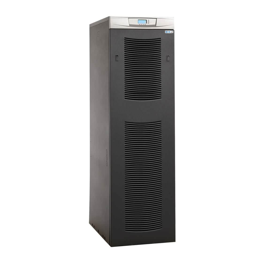
Figure 1 shows the Eaton 9355 UPS.

Figure 1. The Eaton 9355 UPS
Tie Cabinet Installation
The Eaton 9355 has the following power connections:
- 3-phase (L1, L2, and L3), neutral, and ground connection for rectifier/bypass input
- 3-phase (L1, L2, and L3), neutral, and ground connection for load output
The nominal input/output voltages are:
- 120/208 or 127/220 Vac
Output overcurrent protection and disconnect switch must be provided by others.
Figure 9 and Figure 11 show the one-line diagrams.

Figure 9. Parallel Wiring Diagram

Figure 11. Parallel UPS System with Tie Cabinet Diagram (Single-Feed, 208V or 220V Input: 208V or 220V Output)

Only qualified service personnel (such as a licensed electrician) should perform the UPS installation and initial startup. Risk of electrical shock.
To hardwire the Tie Cabinet:
- Verify that the electrical connections to the installation site have been properly installed.
- A wall-mounted, user-supplied, readily-accessible disconnection device must be incorporated in the input wiring.
Compare the circuit breaker ratings to the ones in Table 1.

Table 1. Terminal Block Wiring
1 Use only 90°C-rated copper wire. Minimum wire size is based on 120/208 full load ratings applied to NEC Code Table 310-16. Code may require a larger AWG size than shown in this table because of temperature, number of conductors in the conduit, or long service runs. Follow local requirements.
2 Per NEC article 300-20(a), all three-phase conductors must be run in the same conduit. Neutral and ground must be run in the same conduit as the phase conductors.
3 Conduit is sized to accommodate one neutral conductor the same size as the phase conductor and one ground conductor. If two neutral conductors or an oversized neutral conductor are to be installed, check the size of the conduit needed to accommodate the extra wire or size and use that conduit size in place of the conduit size listed. Conduit sizes were chosen from NEC Table C1, type letters RHH, RHW, RHW-2, TW, THW, THHW, THW-2.
 NOTE: To accommodate the feature of easy system expandability, it is recommended that initial installation of the Eaton 9355 UPS contain wiring to support the maximum capacity of the UPS cabinet.
- Switch off utility power to the distribution point where the Tie Cabinet and UPSs will be connected. Be absolutely sure there is no power.
- Determine your equipment's grounding requirements according to your local electrical code.
- Remove the Tie Cabinet front cover (see Figure 2).

Figure 2. Tie Cabinet Front Cover - Remove the internal covers to gain access to the breakers (see Figure 3).

Figure 3. Internal Covers - Punch holes for the conduit (AC input, UPS output, load connection, and maintenance bypass contact wires) using a Greenlee® punch or similar device.
- Verify that the Tie Cabinet bypass breaker is in the OFF position (see Figure 4).

Figure 4. Tie Cabinet Bypass Breaker - Mount the Tie Cabinet to the wall and install the conduit.
- From each UPS, remove the UPS front door.
- Verify that the UPS input circuit breaker is in the OFF position.
- Verify that each UPS battery circuit breaker is in the OFF position (see Figure 5).

Figure 5. UPS Front View - If you ordered the UPS with the optional output circuit breaker, verify that the output circuit breaker is in the OFF position.
- Remove the UPS wiring access cover and retain.
- Remove the UPS conduit landing box from the rear panel and retain.
- Punch two holes in the conduit landing box for the input and output conduit using a Greenlee punch or similar device.
- Route the wiring from the back of the UPS, through the wiring tray, to the front of the UPS.
- Hardwire the UPS input terminations.


See Table 1 for specifications and Figure 6 for a detailed view of the UPS terminal block.

Figure 6. UPS Terminal Block
NOTE: The two input neutral terminals are jumpered together; use either one of these terminals to make the input neutral connection.
NOTE: The two output neutral terminals are jumpered together; use either one of these terminals to make the output neutral connection.
NOTE1: Input neutral must be wired for proper operation or the UPS will not start.
NOTE2: The Eaton 9355 UPS is shipped as a single-feed UPS and can be converted to a dual feed UPS in the field.
NOTE3: DO NOT overtighten the screws; be sure to use the specified tightening torque values shown in Table 1.
- Hardwire the output terminations from the UPS to the Tie Cabinet (see Figure 7).

Figure 7. UPS Output to Tie Cabinet Wiring - Repeat Step 11 through Step 19 for each UPS.
- Hardwire the load to the Tie Cabinet (see Figure 8).

Figure 8. Load Connections - Wire the maintenance bypass auxiliary contacts and terminate to the maintenance bypass wires in the Tie Cabinet (see Figure 6).
Connect the black and the red wire to TB4 on the UPS (see Figure 9). Cap the blue wire.


NOTE 1 The maintenance bypass contacts are normally-open. To ensure proper bypass operation, DO NOT use the blue wire (it is normally-closed).
NOTE 2 There are two sets of maintenance bypass wires; you can terminate to either set. If you are installing four UPSs, it is recommended to terminate two UPSs to one set of wires and two UPSs to the other set of wires.
- Reinstall the UPS wiring access cover.
- Reinstall the UPS conduit landing box in the reversed position.
- Wire the AC input to the bypass breaker (see Figure 10).

Figure 10. Bypass AC Input Wiring - Verify the phase rotation for each UPS and the bypass input.
- Reinstall the internal cover removed in Step 6.
- Reinstall the Tie Cabinet front covers removed in Step 5.
- Proceed to Installing Options Chapter to continue the installation process.

Installing Options
This section describes the Powerware Hot Sync® CAN Bridge Card.
For other options, such as additional X-Slot® cards, LanSafe® Power Management Software, remote emergency power-off (REPO), relay output contacts, or programmable signal inputs, refer to the Eaton 9355 UPS (20/30 kVA) Installation and Operation Manual.
Figure 12 shows the location of the communication options and control terminals on the UPS.

Figure 12. Communication Options and Control Terminals
Powerware Hot Sync® CAN Bridge Card
The Powerware Hot Sync® CAN Bridge Card, shown in Figure 13, can be installed to provide connectivity for operational mode control and metering of a parallel system at any UPS in the system.

Figure 13. Powerware Hot Sync CAN Bridge Card
To install the ® CAN Bridge Card:
- Remove the UPS front door.
- Remove the communication wiring access plate from the UPS rear panel and punch a hole in it using a Greenlee punch or similar device (see Figure 14).

Figure 14. Communication Wiring Access - Install conduit for the communication wiring.
- Set the jumper pins on the Powerware Hot Sync® CAN Bridge Card according to the parallel configuration (see Figure 15):
")
Figure 15. Setting the CAN Bridge Card Jumper J7 (Side View)- If only two UPSs are paralleled, then set both cards to Pins 1 and 2.
- For three or four paralleled UPSs, set the cards of the first and last UPSs to Pins 1 and 2; set the cards for the middle UPSs to Pins 2 and 3.
- Install the CAN Bridge Card into X-Slot 2 (see Figure 12 and Figure 17).
![]()
Figure 17. Installing Communication Cables - Strip shielded, four-wire, twisted-pair wire (maximum 18 AWG recommended) for CAN Bridge Card wiring and pull-chain wiring.
- Repeat Step 1 through Step 6 for each UPS.
- Route the wiring through the conduit from the communication wiring access plate to the opening between the two X-Slot communication bays on each UPS (see Figure 16).

Figure 16. Routing the Cables - Install the CAN Bridge Card wiring between each UPS (see Figure 18).

Figure 18. CAN Bridge Card and Pull-Chain Wiring
Use three wires of the four-wire twisted-pair wire. (Reserve two wires for pull-chain wiring in Step 11.) Be sure to check correct polarity for Pins 8 and 9:- Connect SHIELD Pin 10 on all cards together.
- Connect CAN H Pin 9 and CAN L Pin 8 (twisted pair) on all cards together.
- Route the pull-chain wiring through the middle of the fan section and secure in the cable clips for each UPS (see Figure 17).
- Wire the pull-chain wiring to Signal Input 2 on each UPS and daisy chain the wiring to each UPS as shown in Figure 18. Be sure to check correct polarity:
- Connect Pull-Chain Output Contact Pin 1 to Signal Input 2 Pin 1 on each UPS.
- Connect Pull-Chain Output Contact Pin 2 to Signal Input 2 Pin 2 on each UPS.

")


If polarity or wiring is not correct, the parallel system does not operate normally. For example, when shutting down one UPS, the remaining UPS transfers the load to bypass instead of supporting the load. Verify all CAN Bridge Card wiring is correct for proper operation.
NOTE: Signal Input 2 can still be used for building alarms; it is automatically rerouted to the CAN Bridge Card.
- Reinstall the communication wiring access plate on each UPS.
- Replace the UPS front door on each UPS.
Safety Warnings
IMPORTANT SAFETY INSTRUCTIONS
SAVE THESE INSTRUCTIONS
This manual contains important instructions that you should follow during installation and maintenance of the UPS and batteries. Please read all instructions before operating the equipment and save this manual for future reference.

This UPS contains LETHAL VOLTAGES. All repairs and service should be performed by AUTHORIZED SERVICE PERSONNEL ONLY. There are NO USER SERVICEABLE PARTS inside the UPS.
- This UPS contains its own energy source (batteries). The UPS output may carry live voltage even when the UPS is not connected to an AC supply.
- To reduce the risk of fire or electric shock, install this UPS in a temperature and humidity controlled, indoor environment, free of conductive contaminants. Ambient temperature must not exceed 40°C (104°F). Do not operate near water or excessive humidity (95% maximum).
- To reduce the risk of fire, connect only to a circuit provided with 125 amperes maximum branch circuit overcurrent protection in accordance with the National Electrical Code, ANSI/NFPA 70.
- Output overcurrent protection and disconnect switch must be provided by others.
- Batteries can present a risk of electrical shock or burn from high short circuit current. Observe proper precautions. Servicing should be performed by qualified service personnel knowledgeable of batteries and required precautions. Keep unauthorized personnel away from batteries.
- Proper disposal of batteries is required. Refer to your local codes for disposal requirements.
- Never dispose of batteries in a fire. Batteries may explode when exposed to flame.
Special Symbols
The following are examples of symbols used on the UPS or accessories to alert you to important information:
 RISK OF ELECTRIC SHOCK - Observe the warning associated with the risk of electric shock symbol.
REFER TO OPERATOR'S MANUAL - Refer to your operator's manual for additional information, such as important operating and maintenance instructions.
 This symbol indicates that you should not discard the UPS or the UPS batteries in the trash. This product contains sealed, lead-acid batteries and must be disposed of properly. For more information, contact your local recycling/reuse or hazardous waste center.
 ON - Indicates that the switch is in the ON position.
 OFF - Indicates that the switch is in the OFF position.
 PHASE - The word "phase."
EQUIPMENT REGISTRATION
Please visit www.eaton.com/pq/register to register your new Eaton UPS / Eaton UPS Accessory.
Documents / ResourcesDownload manual
Here you can download full pdf version of manual, it may contain additional safety instructions, warranty information, FCC rules, etc.
Advertisement


Need help?
Do you have a question about the 9355 and is the answer not in the manual?
Questions and answers