
Related Manuals for Spectrex SharpEye 20


Summary of Contents for Spectrex SharpEye 20
- Page 1 Model 20/20ML UV/IR Mini Flame Detector User Guide 8200 Market Blvd, Chanhassen, MN 55317, USA Phone: +1 (973) 239 8398 Fax: +1 (973) 239 7614 Website: www.spectrex.net Email: spectrex.csc.rmtna@emerson.com...
- Page 3 “Act of God” which are above and beyond its control. SPECTREX will, upon receipt of any defective product, transportation prepaid, repair or replace it at its sole discretion if found to have been defective when shipped. Said repair or replacement is SPECTREX’S sole liability under this warranty and SPECTREX’S liability shall be limited to repair or replacement of the component found...
-
Page 5: Table Of Contents
Table of Contents Table of Contents .................... v List of Figures ....................ix List of Tables ....................ix About this Guide ..................11 Release History ..................11 Glossary and Abbreviations ..............12 Notifications ..................13 Product Overview ..................15 Technical Description ................15 Principles of Operation ................ - Page 6 4.4.4 Manual BIT Only ................28 Technical Specifications ................29 Electrical Specifications ................29 5.1.1 Operating Voltage ................29 5.1.2 Power Consumption ................ 29 5.1.3 Electric Input Protection ..............29 5.1.4 Electrical Outputs ................29 Communications Network............... 30 Mechanical Specifications ............... 30 5.3.1 Enclosure Options ................
- Page 7 6.6.4 Alarm Relay ................... 38 6.6.5 4–20mA Output ................39 6.6.6 RS-485 ..................39 6.6.7 Ground ..................39 Operation Mode ..................39 6.7.1 Programmable Function ..............39 6.7.2 Address ..................39 6.7.3 Alarm Delay ................... 39 Operating Instructions ................41 Scope ....................
- Page 8 Technical Specifications ................. 58 C.3.1 General ..................58 C.3.2 Electrical ..................58 C.3.3 Physical ..................58 C.3.4 EMI Compatibility ................59 Technical Support ..................64 viii SharpEye™ UV/IR Mini Flame Detector User Guide...
- Page 9 List of Figures Figure 1: Model Definitions ................. 17 Figure 2: UV/IR Flame Detector ................17 Figure 3: Flame Detector Assembly: Outline Drawing of Cable Output Option ... 18 Figure 4: Horizontal and Vertical Fields of View ............. 21 Figure 5: 20/20ML LED ..................23 Figure 6: Detector and Tilt Mount Assembly ............
-
Page 11: About This Guide
About this Guide About this Guide This guide describes the SharpEye Model 40/40L, LB, L4, L4B (UV/IR) Flame Detector and its features and provides instructions on how to install, operate, and maintain the detector. Note: This user guide should be read carefully by all individuals who have or will have responsibility for using, maintaining, or servicing the product. -
Page 12: Glossary And Abbreviations
About this Guide Glossary and Abbreviations Abbreviation/Term Meaning Analog Video Video values are represented by a scaled signal ATEX Atmosphere Explosives American Wire Gauge Built-In-Test Complementary Metal-Oxide Semiconductor image CMOS sensor Each component is represented by a number Digital Video representing a discrete quantization Digital Signal Processing Electromagnetic Compatibility... -
Page 13: Notifications
About this Guide Abbreviation/Term Meaning Radio Frequency Interference RTSP Real Time Streaming Protocol Safety Integrity Level Unified Coarse Thread Volts Alternating Current Notifications This section explains and exemplifies the usage of warnings, cautions, and notes throughout this guide: Warning: This indicates a potentially hazardous situation that could result in serious injury and/or major damage to the equipment. -
Page 15: Product Overview
Product Overview Product Overview The SPECTREX Model 20/20ML UV/IR Flame Detectors are designed to sense the occurrence of fire and flames and subsequently activate an alarm or an extinguishing system, directly or through a control circuit, for maximum fire protection. They use the innovative technology of advanced digital signal processing to analyze the dynamic characteristics of fire. -
Page 16: Sensing Elements
Product Overview The UV-IR Radiation Flame Detector is a dual spectrum optical detector sensitive to 2 separate ranges of the radiation spectrum, both of which are present in fires. The detector monitors the protected area, by measuring the radiation intensity in it, within 2 frequency ranges of the electromagnetic spectrum, namely the Ultra- Violet (UV) and the Infra-Red (IR). -
Page 17: Figure 1: Model Definitions
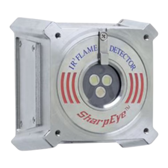
Product Overview Figure 1: Model Definitions Figure 2: UV/IR Flame Detector TM767100 Rev. (Ad), May 2019... -
Page 18: Figure 3: Flame Detector Assembly: Outline Drawing Of Cable Output Option
Product Overview Figure 3: Flame Detector Assembly: Outline Drawing of Cable Output Option SharpEye™ UV/IR Mini Flame Detector User Guide... -
Page 19: Performance
Performance Performance Detection Sensitivity Detection sensitivity is the maximum distance at which the detector will reliably detect a specific size of fire and a typical type of fuel (standard fire). 3.1.1 Standard Fire A 1ft /0.1m gasoline pan fire with a max. wind speed of 6.5ft/sec / 2m/sec. 3.1.2 Sensitivity Ranges: The detector has 2 user selectable sensitivity ranges. -
Page 20: Other Fuels
Performance 3.1.3 Other Fuels The detector will react to other types of fires as follows: • Pan fire size: 1ft /0.1m • Maximum wind speed: 6.5ft/sec / 2m/sec • Maximum response time: 10 sec Table 1: Response Sensitivity Ranges for Other Fuels Max. -
Page 21: Cone Of Vision
Performance Cone of Vision Horizontal: 100° Vertical: 100° Figure 4: Horizontal and Vertical Fields of View False Alarms Prevention The detector will not provide an alarm or a warning signal as a reaction to the radiation sources specified below. False alarm immunity is listed in Table 2. Notes: IAD = Immune at Any Distance All sources are chopped from 0 to 20Hz... -
Page 22: Table 2: 20/20Ml - Immunity To False Alarm Faults
Performance Table 2: 20/20ML - Immunity to False Alarm Faults Immunity Radiation Source Distance (ft/m) Sunlight Indirect or reflected sunlight Vehicle headlights (low beam) conforming to MS53023-1 Incandescent frosted glass light, 100W Incandescent clear glass light, rough service, 100W Fluorescent light with white enamel reflector, standard office or shop, 40W (or two 20W) Arc welding [4mm/ 5/32”... -
Page 23: Operation
Operation Operation Visual Indications One 3-color LED-indicator is located in the detector front window: Detector Status LED Color LED Mode Fault, BIT Fault Yellow 4Hz flashing Normal Green 1Hz flashing Warning 2Hz flashing Alarm Steady Figure 5: 20/20ML LED Output Signals The detector provides the following outputs: •... -
Page 24: Optional Latching
Operation Table 3: Detector States Detector State Description The detector is functioning normally. Normal The detector performs a Built-In-Test. Fire detected – warming alarm (pre-alarm) state. Warning Fire detected – fire alarm state. Alarm The alarm outputs are latched due to the detection Latched Alarm of a fire that has already been extinguished. -
Page 25: Built-In-Test
See Detector Default Setup on page 26 for default factory settings. The 20/20ML incorporates several functions that can be set by the customer using SPECTREX Host software, which will be supplied for each detector shipment. The Host software enables you to change functions, as described in Detector’s Various Functions on page 25. -
Page 26: Detector Default Setup
Operation Table 5: Time Delay Delay (seconds) – anti-flare Default 4.3.2.4 Function Setup The user can select the desired mode of operation by means of the host. Table 6: Function Setup Name Alarm latching enable Alarm latching disable Alarm latch (default) Automatic and manual A manual BIT only... -
Page 27: Built-In-Test
Operation Table 7: Default Function Setup Detector Default Setup 20/20ML Delay Alarm Latch Automatic BIT Alarm BIT Built-In-Test 4.4.1 General The detector’s Built-In-Test (BIT) checks the following: • Electronic circuitry • Sensors • Window cleanliness The detector can be set to perform the BIT automatically and manually, or manually only. -
Page 28: Manual Bit Only
Operation • The Fault relay is opened. • 4–20mA output indicates a BIT Fault (2mA). • The LED flashes (4Hz) at yellow. • A BIT procedure will be performed every minute. 4.4.3.2 Manual BIT Functions as described in Manual BIT Only on page 28. In the case of an unsuccessful BIT, all outputs will function as described in Manual BIT Only;... -
Page 29: Technical Specifications
Technical Specifications Technical Specifications Electrical Specifications 5.1.1 Operating Voltage • 18–32 VDC 5.1.2 Power Consumption • Max. 35mA in Standby • Max. 80mA in Alarm 5.1.3 Electric Input Protection The input circuit is protected against voltage-reversed polarity, voltage transients, surges, and spikes, according to MIL-STD-1275A. 5.1.4 Electrical Outputs 5.1.4.1... -
Page 30: Communications Network
It enables continuous communications between a single standard Modbus controller (master device) and a serial network of up to 247 detectors. • It enables connection between different types of SPECTREX detectors or other Modbus devices to the same network. Mechanical Specifications 5.3.1... -
Page 31: Low Temperature
Technical Specifications 5.4.2 Low Temperature • Design to meet MIL-STD-810C, Method 502.1, Procedure I • Operating temperature: -40°F/-40°C • Storage temperature: -65°F/-55°C 5.4.3 Humidity • Designed to meet MIL-STD-810C, Method 507.1, Procedure IV • Relative humidity of up to 95% for the operational temperature range 5.4.4 Salt Fog •... -
Page 33: Installation Instructions
Installation Instructions Installation Instructions Scope The SharpEye Model 20/20ML is a self-contained optical flame detector designed to operate as a stand-alone unit, directly connected to alarm systems or to automatic fire extinguishing systems. The detector can be part of a more complex system where many detectors and other devices are integrated through a common control unit. -
Page 34: Preparation For Installation
Installation Instructions 6.2.1.3 Environment • Dust, snow, or rain can reduce the detector’s sensitivity and require more maintenance activities. • The presence of high intensity flickering of IR sources may affect sensitivity. Preparation for Installation Installation should comply with local codes or NFPA as applicable to flame detectors. -
Page 35: Tilt Installation
Installation Instructions 6.4.2 Tilt Installation For tilt installation, see Figure 6 and Figure 7. Place the tilt mount (Item 1) in its designated location and secure it with 3 fasteners through 3 holes of dia. 5.2mm. Note: Skip this step if the tilt mount is already installed. Also, detector removal does not require tilt mount removal for maintenance purposes. -
Page 36: Figure 6: Detector And Tilt Mount Assembly
Installation Instructions Item Description Tilt mount plate Detector holding plate Mounting plate Locking screw Holding screws Washers IR detector direct mounting holes Figure 6: Detector and Tilt Mount Assembly SharpEye™ UV/IR Mini Flame Detector User Guide... -
Page 37: Figure 7: Tilt Mount Assembly - Outline Drawing
Installation Instructions Item Description Tilt mount Detector holding plate Mounting plate Locking screw Figure 7: Tilt Mount Assembly - Outline Drawing TM767100 Rev. (Ad), May 2019... -
Page 38: Detector Mounting
Installation Instructions Detector Mounting These detectors are not approved for location in hazardous classified areas. Choose the wiring configuration according to Appendix A: on page 47. Connect the wire to the required PIN on the connector or choose the required color on the cable, according to your wiring diagram. -
Page 39: 4-20Ma Output
The detector is supplied with a default function setup (see Table 7). The function setup can be reprogrammed by the user through RS-485 using a PC with SPECTREX host software or through use of a handheld unit. Refer to TM784050 for instructions. -
Page 41: Operating Instructions
Operating Instructions Operating Instructions Scope The following instructions are designed to obtain optimal performance from the detector over its lifecycle. Power-Up Turn on the detector and wait approximately 60 seconds for the detector’s automatic self-test. Note: Turning on the detector initiates the following sequence: The LED flashes (4Hz) yellow •... -
Page 42: Reset
Reset only when the optional latching alarm has been selected. Functional Testing Following is a testing procedure for proper functioning of the detector. The detector can be tested using the manual Built-in-Test or the SPECTREX Flame Simulator FS-1200. 7.4.1 Manual BIT Test Momentarily connecting Pin no. -
Page 43: Safety Precautions
Normal state and the LED to flash (1Hz) green. If the detector is on, skip this step. Aim the SPECTREX Flame Simulator Model FS1200 at the detector’s target point (see Figure 15), in a way that the radiation emitted by it is facing directly towards the detector. -
Page 45: Maintenance Instructions
Maintenance Instructions Maintenance Instructions Scope This chapter deals with preventive maintenance, describes possible faults in detector operation, and indicates corrective measures. Ignoring these instructions may cause problems with the detector and may invalidate the warranty. Whenever a unit requires service, please contact the manufacturer or its authorized distributor for assistance. -
Page 46: Maintenance Records
Maintenance Instructions Maintenance Records It is recommended to record maintenance operations performed on a detector in a system logbook. The record should include information that identifies the unit, the installation date, contractor, and entries for every maintenance operation performed including the description of the operation, date, and personnel ID. If a unit is sent to the manufacturer or distributor for service, a copy of the maintenance records should accompany it. -
Page 47: Appendix A: Typical Wiring Configurations
Typical Wiring Configurations Appendix A: Typical Wiring Configurations Figure 8: Connector Interface Option TM767100 Rev. (Ad), May 2019... -
Page 48: Rs-485 Communications Network
Typical Wiring Configurations Figure 9: Cable Interface Option RS-485 Communications Network Using the RS-485 network capability of the IR detector and control software, it is possible to connect up to 32 detectors in an addressable system with 4 wires only (2 for power and 2 for communications). -
Page 49: Figure 10: Rs-485 Networking
Typical Wiring Configurations Figure 10: RS-485 Networking Figure 11: 4–20mA Wiring (Sink Option) TM767100 Rev. (Ad), May 2019... -
Page 50: Figure 12: 4-20Ma Wiring (Source Option)
Typical Wiring Configurations Figure 12: 4–20mA Wiring (Source Option) Notes: The detectors are factory set to isolated 4-20mA-sink version. • To work at non-isolated 4–20mA source version, connect Pin 3 • (blue wire) to Pin 1 (red wire). This can be done on the mating connector or in the junction box in the cable option. - Page 51 Typical Wiring Configurations Notes: For EOL resistor value, see the Controller Manual. • The color wire refers to the color of the cable output option. The • Pin no. refers to the connector option TM767100 Rev. (Ad), May 2019...
-
Page 53: Appendix B: Flame Simulator Fs-1200
Flame Simulator FS-1200 Appendix B: Flame Simulator FS-1200 The Flame Simulator FS-1200 is designed specifically for use with SharpEye flame detectors. The FS-1200 includes a halogen lamp that emits UV and IR energy. This energy is accumulated by a reflector directed towards the detector, which allows the detectors to be tested under simulated fire conditions without the associated risks of an open flame. -
Page 55: Appendix C: Ordering Information
Ordering Information Appendix C: Ordering Information The P/N of the Flame Simulator Kit is 380114-2. The kit is supplied in a carry case that includes: • Flame Simulator FS-1200 • Charger • Tool Kit • Technical Manual TM380102 Unpacking Verify that you have received the following contents: •... -
Page 56: Range
Ordering Information To simulate a fire: Verify you are at the correct distance from the detector according to the type of detector and the detector sensitivity. Using the mechanical sight, aim the flame simulator toward the center of the detector. Push the activate button, and then use the laser spot for fine adjustment toward the center of the detector. -
Page 57: Figure 15: Flame Simulator Battery Replacement
Ordering Information Item Description Simulator Battery pack Locking disc Back cover Figure 15: Flame Simulator Battery Replacement To charge the battery: Place the flame simulator on a table in a safe area, not exceeding 104°F/40°C. Release the locking screw. Unscrew the battery back cover (Item 4) counterclockwise. Unscrew the locking disc (Item 3) clockwise. -
Page 58: Replacing The Battery
Unscrew the battery back cover (Item 4) counterclockwise. Unscrew the locking disc (Item 3) clockwise. Pull out the battery from the flame simulator. Insert the new battery pack in the simulator housing. Use only the SPECTREX battery pack, P/N 380004. Screw on the locking disc (Item 3). -
Page 59: Emi Compatibility
Ordering Information • Explosion proof enclosure: • ATEX and IECEx • Ex II 2 G D • Ex d ib op is IIB +H2 T5 Gb • –20°C to +50°C / –4°F to +122°F C.3.4 EMI Compatibility Table 11: Immunity Tests Immunity Tests Title Basic Standard... -
Page 64: Technical Support
Technical Support For technical assistance or support, contact: 8200 Market Blvd Chanhassen, MN 55317 Phone: +1 (973) 239 8398 Fax: +1 (973) 239 7614 Email: spectrex.csc.rmtna@emerson.com Website: www.spectrex.net...
Need help?
Do you have a question about the SharpEye 20 and is the answer not in the manual?
Questions and answers