Table of Contents
Advertisement
Quick Links
1101 SERIES WIRELESS
UNIVERSAL TRANSMITTER
Installation Guide
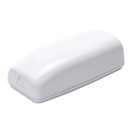
Figure 1: 1101 Wireless Transmitter
DESCRIPTION
The 1101 Series Wireless Universal
Transmitters are two‑way
supervisory wireless transmitters
typically used for door and window
applications. The 1101E features
128‑bit AES encryption.
The transmitter provides a cover
tamper, magnetic reed switch,
and an onboard terminal block to
allow for external contact wiring.
Both sets of contacts, internal and
external, can be programmed to
operate at the same time. This
allows two independent zones to
operate from one 1101.
The 1101 Series also features
Disarm/Disable functionality. When
this option is enabled, Zone Tripped
messages are disabled when the
system is disarmed.
Compatibility
All DMP XT Series and XR Series and
all 1100 Series Wireless Receivers.
To enable encryption on 1101E models,
Version 183 is required for XT and XR
Series panels. Version 300 is required
for wireless receivers.
What is Included?
•
One 1101 Wireless Universal
Transmitter
•
One Magnet with Standard and
Commercial Housing
•
One 3.0 V lithium CR123A battery
•
Hardware pack
1
PROGRAM THE PANEL
Refer to the panel programming guide as needed. After completing
each of the following steps, press CMD to advance to the next
prompt.
At a keypad, enter 6653 (PROG) to access the Programmer
1.
Menu.
2.
(1101E only) Go to SYSTEM OPTIONS. At 1100 ENCRYPTION,
select ALL to only add encrypted wireless devices to
the system. Select BOTH to allow both encrypted and
non‑encrypted wireless devices to be programmed.
3.
(1101E only) The default passphrase appears at the ENTER
PASSPHRASE prompt. Press CMD to keep the default. Press
any select key or area to change the passphrase and enter
an 8‑character hexadecimal string (0‑9, A‑F).
At ZONE INFORMATION, enter the wireless zone number.
4.
5.
At *UNUSED*, enter the zone name.
6.
At ZONE TYPE, press any select key or area and select the
zone type.
At the NEXT ZN? prompt, select NO.
7.
8.
When WIRELESS? displays, select YES.
9.
At SERIAL#, enter the eight‑digit device serial number.
10. At CONTACT, select either INTERNAL or EXTERNAL.
Note: Use consecutive zone numbers if using both
internal and external contacts.
11. At SUPRVSN TIME, enter a supervision time. Default is 240.
12. At DISARM DISABLE, select NO or YES.
Note: Program the external contact first if using both
internal and external contacts with Disarm/Disable
functionality.
13. At the NEXT ZONE prompt, select YES if you are finished
programming the zone. Select NO if you would like to access
additional programming options.
14. To save panel programming, go to STOP and press CMD.
2
INSTALL THE BATTERY
Use a 3.0 V lithium battery, a DMP Model CR123A battery, or an
equivalent model from Sony or Murata. For listed installations,
use either an Energizer® 123 battery or a CR123A battery
manufactured by Panasonic or Tekcell.
1.
Push the button on the end of the 1101 and separate the
two halves.
2.
Observing polarity, place the battery in the holder and
press it into place. Refer to Figure 2 during installation.
Advertisement
Table of Contents

Related Manuals for DMP Electronics 1101 Series


Summary of Contents for DMP Electronics 1101 Series
-
Page 1: What Is Included
1101 SERIES WIRELESS UNIVERSAL TRANSMITTER Installation Guide PROGRAM THE PANEL Refer to the panel programming guide as needed. After completing each of the following steps, press CMD to advance to the next prompt. At a keypad, enter 6653 (PROG) to access the Programmer Menu. -
Page 2: Select A Location
SELECT A LOCATION The 1101 provides a Survey LED capability to allow one person to confirm communication with the wireless receiver or panel while the cover is removed. With the cover removed, hold the transmitter in the desired location. Press the tamper switch to send data to the panel and determine if communication is confirmed or faulty. -
Page 3: Additional Information
WIRE EXTERNAL CONTACTS (OPTIONAL) Refer to Zone Information in the appropriate panel programming guide for more information. DMP recommends using 18 or 22 AWG unshielded wire for contact connections. Do not use twisted pair or shielded wire. Refer to Figure 6 when wiring external contacts. Use a flathead screwdriver to loosen the two external contact terminal screws. -
Page 4: Fcc Information
établies par le Code de sécurité 6 de Santé Canada. Le système doit être installé à une distance minimale de 7.87 pouces (20 cm) séparant l’antenne d’une personne présente en conformité avec les limites permises d’exposition du grand public. 1101 SERIES UNIVERSAL Patents U. S. Patent No. 7,239,236...
Need help?
Do you have a question about the 1101 Series and is the answer not in the manual?
Questions and answers