Spirax Sarco STAPs Quick Installation Manual
Wireless head unit
Hide thumbs
Also See for STAPs:
- Installation and maintenance instructions manual (25 pages) ,
- Quick installation manual (36 pages)
Table of Contents
Advertisement
Quick Links
0140051/2
IM-P014-16 MI Issue 2
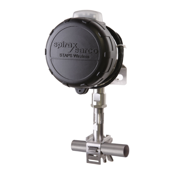
STAPS
Wireless Head Unit
Quick Installation Guide
IM-P014-16
1. Safety information
2. General product
information
3. Order of installation
4. Installation of head
5. Spare parts
6. Certification and
approvals
7. Technical data
8. Technical glossary
© Copyright 2015
MI Issue 2
1
Printed in GB
Advertisement
Table of Contents

Related Manuals for Spirax Sarco STAPs


Summary of Contents for Spirax Sarco STAPs
- Page 1 0140051/2 IM-P014-16 MI Issue 2 STAPS Wireless Head Unit Quick Installation Guide 1. Safety information 2. General product information 3. Order of installation 4. Installation of head 5. Spare parts 6. Certification and approvals 7. Technical data 8. Technical glossary ©...
-
Page 2: Safety Information
Determine the correct installation situation and direction of fluid flow. iv) Spirax Sarco products are not intended to withstand external stresses that may be induced by any system to which they are fitted. It is the responsibility of the installer to consider these stresses and take adequate precautions to minimise them. -
Page 3: Pressure Systems
1.9 Tools and consumables Before starting work ensure that you have suitable tools and / or consumables available. Use only genuine Spirax Sarco replacement parts. 1.10 Protective clothing Consider whether you and / or others in the vicinity require any protective clothing to protect against the hazards of, for example, chemicals, high / low temperature, radiation, noise, falling objects, and dangers to eyes and face. - Page 4 1.16 Returning products Customers and stockists are reminded that under EC Health, Safety and Environment Law, when returning products to Spirax Sarco they must provide information on any hazards and the precautions to be taken due to contamination residues or mechanical damage which may present a health, safety or environmental risk.
-
Page 5: General Product Information
- See software IMI for commissioning the unit into operation. Each STAPS head unit assembly is powered by a long life Lithium battery (typical battery life of over 3 years). It can communicate directly to a receiver that is connected to the PC software via a LAN connection or via another intelligent head or repeater. -
Page 6: Order Of Installation
IM-P014-24 STAPS Wireless Steam Trap Monitoring System Installation and Operating Instructions for use with Windows XP operating systems To ensure that the STAPS system operates correctly adhere to Section 3.2 and you must follow the sequence of installation specified in Section 3.3 3.2 Before Installation:... -
Page 7: Recommended Order Of Installation
12. Using the software, assign a trap to the Head, refer to Section 5.6 - Assigning traps to Heads IM-P014-26 or IM-P014-24. 13. Repeat Steps 6 to 8 for other STAPS Heads until all traps to be monitored within signal range are completed. - Page 8 4. Installation of the head unit assembly Note: Before actioning any installation observe the 'Safety information' in Section 1. The STAPS sensor includes the following parts: 1 off head and sensor assembly, 1 o f f l o w e r...
- Page 9 Installation - Is there sufficient room at the sensor for the head to be mounted on the sensor or locally within 1 m? Lagging - Ensure that any pipe lagging in the area where the STAPS head is to be fitted is removed before fitting. DO NOT re-lag the STAPS head unit, including the clamp and stem.
- Page 10 4.1.3 Turn head cover anticlockwise and align the cover lug with the arrow on the body and pull the cover away from the body. Fig. 8 IM-P014-16 MI Issue 2...
- Page 11 4.1.4 Remove the packaging from the battery and push it into the holder in the head unit. Ensure that the battery is in the correct orientation as per the orientation marker (+ to top). Note: Only use a SAFT LS 33600 Lithium Thionyl Chloride 3.6 V battery. Fig.
- Page 12 Mounting the head unit Ensure that any pipe lagging is removed from the area where the STAPS head is to be fitted. DO NOT re-lag the STAPS Head. 4.2.1 For pipe sizes ½" to 1¼" Slide the tongue of the lower clamp into the appropriate slot of the top clamp.
- Page 13 Caution: If fitted to a hot pipe, recheck that the clamp is tight after 15 minutes. Maximum 150 mm Fig. 13 Fig. 14 IM-P014-16 MI Issue 2...
- Page 14 4.2.2 For pipe sizes 1½", 2" - 2½" and 3" - 4" The larger sizes use jubilee clips rather than a clamp to attach the head unit to the pipe. Separate the jubilee clips and slide over the pipe and loosely tighten the clip to the pipe, allowing room to push the top clamp under.
- Page 15 4.2.3 Fitting the STAPS head to the STS17 or STS17.2 Separate the 'U' bolt from the top clamp. Slide the 'U' bolt around the Universal Flange on the STS17.2 casting and place the top clamp such that the STAPS sensor is upright and in contact with the top of the universal flange.
- Page 16 'U' bolt is not suitable, the head can be secured using zip ties (not supplied). Fig. 20 Do not attach the head directly to the steam pipe or any other hot structure. Do not lag the STAPS head unit, including the clamp and stem. IM-P014-16 MI Issue 2...
-
Page 17: Software Copyright
Fig. 21 Important: Make sure that MAC ID is noted against a trap type and reference location. This data will be required for entry into the STAPS software - See Software copyright statement below. Information required: 1. Location reference / trap tag No. -
Page 18: Spare Parts
Example: 1 off Battery spares kit (SAFT LS 33600 3.6 V battery) for a STAPS wireless steam trap monitoring system. 1 off Clamp for use with an STS17.2 pipeline trapping station. -
Page 19: Certification And Approvals
6. Certification and approvals United States - Standards used for Certification: FM3600, FM3610, FM3810, ASME / ISA 60079-0 and ASME / ISA 60079-11 Canada Standards used for Certification: CSA 1010.1, CSA C22.2 No.157, CSA C22.2 No.25, CAN / CSAE 60079-0 and CAN / CSA 60079-11 Note: The above approvals are only valid if the product is installed using the genuine supplied component parts and accessories, including consumable items such as batteries and power... -
Page 20: Technical Glossary
This individual should be able to supply the required advise and details to install the STAPS system onto your companies network. Orifice Size The orifice size is the size of the hole in the trap seat that the condensate passes through.
Need help?
Do you have a question about the STAPs and is the answer not in the manual?
Questions and answers