Table of Contents
Advertisement
Quick Links
Using the TPS53647: PWR710-EVM, 4-Phase, D-CAP+
Step-Down, DC-DC Analog with PMBus Interface
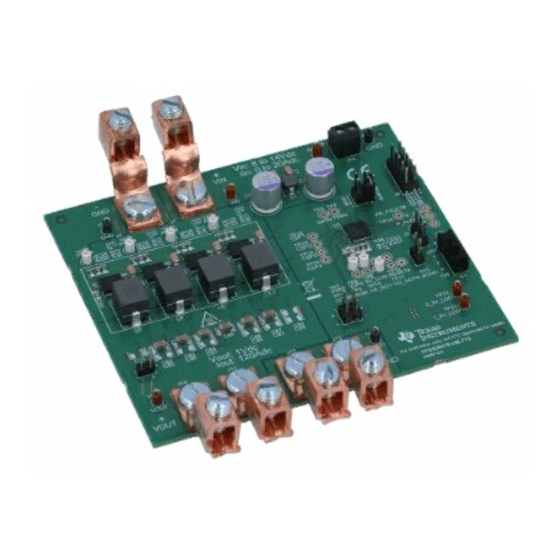
The PWR710-EVM evaluation module (EVM) uses the TPS53647 controller. The controller is 4-phase, D-
CAP+™ synchronous buck driverless controller with PMBus™ interface. The device operates using a
voltage supply between 4.5 V and 17 V. The controller allows programming and monitoring via the PMBus
interface. This PWR710-EVM uses the CSD95372B, Synchronous Buck NexFET™ Smart Power Stage
(SLPS499) device as the power stage.
....................................................................................................................
1
1.1
1.2
2
.....................................................................................................................
3
....................................................................................................................
4
4.1
4.2
4.3
4.4
4.5
5
5.1
6
6.1
6.2
6.3
6.4
7
8
9
..................................................................................................................
10
1
The PWR710-EVM operates as a single output converter. The nominal 12-V bus produced a regulated,
1.0-V output at up to 120 A of load current. The PWR710-EVM demonstrates the controller in a typical
low-voltage high-current application while providing a number of test points to evaluate the performance of
the controller. Refer to TPS53647 (SLUSC39) datasheet for more information on multi-phase
configuration.
1.1
Typical Applications
•
ASIC power in communications equipment
•
High density power solutions
•
Server power
•
Smart power systems
SLUUBA9A - June 2015 - Revised February 2017
Submit Documentation Feedback
................................................................................................
..............................................................................................................
.....................................................................................
.................................................................................
.....................................................................................................
........................................................................................
..............................................................................
.............................................................................
..............................................................................
.........................................................................................
.............................................................................................................
...........................................................................................................
..............................................................................
..............................................................................
.............................................................................................................
Using the TPS53647: PWR710-EVM, 4-Phase, D-CAP+ Step-Down, DC-DC
Copyright © 2015-2017, Texas Instruments Incorporated
SLUUBA9A - June 2015 - Revised February 2017
Contents
.............................................
....................................................
.................................................................
User's Guide
Analog with PMBus Interface
1
1
2
2
3
8
8
8
9
10
11
13
13
13
13
14
14
15
16
19
22
24
1
Advertisement
Table of Contents

Related Manuals for Texas Instruments TPS53647


Summary of Contents for Texas Instruments TPS53647
-
Page 1: Table Of Contents
Using the TPS53647: PWR710-EVM, 4-Phase, D-CAP+ Step-Down, DC-DC Analog with PMBus Interface The PWR710-EVM evaluation module (EVM) uses the TPS53647 controller. The controller is 4-phase, D- CAP+™ synchronous buck driverless controller with PMBus™ interface. The device operates using a voltage supply between 4.5 V and 17 V. The controller allows programming and monitoring via the PMBus interface. -
Page 2: Features
Full-load efficiency = 12 V, I = 120 A Operating temperature ºC Using the TPS53647: PWR710-EVM, 4-Phase, D-CAP+ Step-Down, DC-DC SLUUBA9A – June 2015 – Revised February 2017 Analog with PMBus Interface Submit Documentation Feedback Copyright © 2015–2017, Texas Instruments Incorporated... -
Page 3: Schematic
VR_HOT# AGND PWRGND VR_RDY VR_FAULT# VR_HOT# Figure 1. PWR710-EVM Schematic Controller SLUUBA9A – June 2015 – Revised February 2017 Using the TPS53647: PWR710-EVM, 4-Phase, D-CAP+ Step-Down, DC-DC Analog with PMBus Interface Submit Documentation Feedback Copyright © 2015–2017, Texas Instruments Incorporated... - Page 4 CSP3 IOUT PGND CSD95372BQ5M 1000pF 1.00 VREF Figure 4. Phase 3 Using the TPS53647: PWR710-EVM, 4-Phase, D-CAP+ Step-Down, DC-DC SLUUBA9A – June 2015 – Revised February 2017 Analog with PMBus Interface Submit Documentation Feedback Copyright © 2015–2017, Texas Instruments Incorporated...
- Page 5 CSP4 IOUT PGND CSD95372BQ5M 1000pF 1.00 VREF Figure 5. Phase 4 SLUUBA9A – June 2015 – Revised February 2017 Using the TPS53647: PWR710-EVM, 4-Phase, D-CAP+ Step-Down, DC-DC Analog with PMBus Interface Submit Documentation Feedback Copyright © 2015–2017, Texas Instruments Incorporated...
- Page 6 Schematic www.ti.com Figure 6. Output Filter Using the TPS53647: PWR710-EVM, 4-Phase, D-CAP+ Step-Down, DC-DC SLUUBA9A – June 2015 – Revised February 2017 Analog with PMBus Interface Submit Documentation Feedback Copyright © 2015–2017, Texas Instruments Incorporated...
- Page 7 Schematic www.ti.com Figure 7. Auxiliary Circuitry SLUUBA9A – June 2015 – Revised February 2017 Using the TPS53647: PWR710-EVM, 4-Phase, D-CAP+ Step-Down, DC-DC Analog with PMBus Interface Submit Documentation Feedback Copyright © 2015–2017, Texas Instruments Incorporated...
-
Page 8: Test Setup
9. To purchase this adapter visit the TI usb- to-gpio tool page. 4.2.7 Recommended Wire Gauge Using the TPS53647: PWR710-EVM, 4-Phase, D-CAP+ Step-Down, DC-DC SLUUBA9A – June 2015 – Revised February 2017 Analog with PMBus Interface Submit Documentation Feedback Copyright © 2015–2017, Texas Instruments Incorporated... -
Page 9: Recommended Test Setup
VIN and 5VIN input voltage sources, output load, and USB-to-GPIO adapter. Figure 8. PWR710-EVM Recommended Test Setup SLUUBA9A – June 2015 – Revised February 2017 Using the TPS53647: PWR710-EVM, 4-Phase, D-CAP+ Step-Down, DC-DC Analog with PMBus Interface Submit Documentation Feedback Copyright © 2015–2017, Texas Instruments Incorporated... -
Page 10: Usb Interface Adapter And Cable
Figure 9 shows the USB interface adapter and cable. Figure 9. Texas Instruments USB-to-GPIO Adapter and Connections Using the TPS53647: PWR710-EVM, 4-Phase, D-CAP+ Step-Down, DC-DC SLUUBA9A – June 2015 – Revised February 2017 Analog with PMBus Interface Submit Documentation Feedback... -
Page 11: List Of Test Points And Connectors
TSW-102-07- Choose NVM or pin strap TSW-105-07- PMBus connector TSW-102-07- Reset SLUUBA9A – June 2015 – Revised February 2017 Using the TPS53647: PWR710-EVM, 4-Phase, D-CAP+ Step-Down, DC-DC Analog with PMBus Interface Submit Documentation Feedback Copyright © 2015–2017, Texas Instruments Incorporated... - Page 12 + connector CB35-36-CY - connector CB35-36-CY - connector ED555/2DS 5VIN connector Using the TPS53647: PWR710-EVM, 4-Phase, D-CAP+ Step-Down, DC-DC SLUUBA9A – June 2015 – Revised February 2017 Analog with PMBus Interface Submit Documentation Feedback Copyright © 2015–2017, Texas Instruments Incorporated...
-
Page 13: Evm Configuration Using The Fusion Gui
12. Decrease 5VIN to 0 V. 13. Shut down the external fan if in use. SLUUBA9A – June 2015 – Revised February 2017 Using the TPS53647: PWR710-EVM, 4-Phase, D-CAP+ Step-Down, DC-DC Analog with PMBus Interface Submit Documentation Feedback Copyright © 2015–2017, Texas Instruments Incorporated... -
Page 14: Control Loop Gain And Phase Measurement Procedure
Using these measurement points results in efficiency measurements that do not include losses due to the connectors and PCB traces. Using the TPS53647: PWR710-EVM, 4-Phase, D-CAP+ Step-Down, DC-DC SLUUBA9A – June 2015 – Revised February 2017 Analog with PMBus Interface Submit Documentation Feedback Copyright ©... -
Page 15: Equipment Turn-On And Shutdown
4. Shut down input power supply 5VIN. 5. Shut down the external FAN if in use. SLUUBA9A – June 2015 – Revised February 2017 Using the TPS53647: PWR710-EVM, 4-Phase, D-CAP+ Step-Down, DC-DC Analog with PMBus Interface Submit Documentation Feedback Copyright © 2015–2017, Texas Instruments Incorporated... -
Page 16: Performance Data And Typical Characteristic Curves
Figure 13. Bode Plot (V = 12 V, V = 1.0 V, I = 120A) Using the TPS53647: PWR710-EVM, 4-Phase, D-CAP+ Step-Down, DC-DC SLUUBA9A – June 2015 – Revised February 2017 Analog with PMBus Interface Submit Documentation Feedback Copyright © 2015–2017, Texas Instruments Incorporated... - Page 17 Figure 16. Transient Response (Load Step 0 A to 40 A to Figure 17. Output Ripple 0A, 5A/us Slew Rate) SLUUBA9A – June 2015 – Revised February 2017 Using the TPS53647: PWR710-EVM, 4-Phase, D-CAP+ Step-Down, DC-DC Analog with PMBus Interface Submit Documentation Feedback Copyright © 2015–2017, Texas Instruments Incorporated...
- Page 18 VIN = 12 V, VOUT = 1 V, IOUT = 6 A Figure 18. Enable Startup Figure 19. Enable Shutdown Using the TPS53647: PWR710-EVM, 4-Phase, D-CAP+ Step-Down, DC-DC SLUUBA9A – June 2015 – Revised February 2017 Analog with PMBus Interface Submit Documentation Feedback Copyright ©...
-
Page 19: Evm Assembly Drawing And Pcb Layout
Figure 23. Internal Layer 1 (Top View) Figure 22. Top Copper (Top View) SLUUBA9A – June 2015 – Revised February 2017 Using the TPS53647: PWR710-EVM, 4-Phase, D-CAP+ Step-Down, DC-DC Analog with PMBus Interface Submit Documentation Feedback Copyright © 2015–2017, Texas Instruments Incorporated... - Page 20 Figure 24. Internal Layer 2 (Top View) Figure 26. Internal Layer 4 (Top View) Figure 27. Internal Layer 5 (Top View) Using the TPS53647: PWR710-EVM, 4-Phase, D-CAP+ Step-Down, DC-DC SLUUBA9A – June 2015 – Revised February 2017 Analog with PMBus Interface Submit Documentation Feedback Copyright ©...
- Page 21 Figure 28. Internal Layer 6 (Top View) Figure 29. Bottom Copper (Top View) SLUUBA9A – June 2015 – Revised February 2017 Using the TPS53647: PWR710-EVM, 4-Phase, D-CAP+ Step-Down, DC-DC Analog with PMBus Interface Submit Documentation Feedback Copyright © 2015–2017, Texas Instruments Incorporated...
-
Page 22: List Of Materials
CB35-36-CY Panduit J12, J13 component of quantity 0 indicates not populated. Using the TPS53647: PWR710-EVM, 4-Phase, D-CAP+ Step-Down, DC-DC SLUUBA9A – June 2015 – Revised February 2017 Analog with PMBus Interface Submit Documentation Feedback Copyright © 2015–2017, Texas Instruments Incorporated... - Page 23 TP29 5VIN, Test Point, Miniature, Red, TH Red Miniature Testpoint Keystone SLUUBA9A – June 2015 – Revised February 2017 Using the TPS53647: PWR710-EVM, 4-Phase, D-CAP+ Step-Down, DC-DC Analog with PMBus Interface Submit Documentation Feedback Copyright © 2015–2017, Texas Instruments Incorporated...
-
Page 24: Fusion Gui
• OC Fault and OC Warn Limits • OC Fault and OC Warn Limits Using the TPS53647: PWR710-EVM, 4-Phase, D-CAP+ Step-Down, DC-DC SLUUBA9A – June 2015 – Revised February 2017 Analog with PMBus Interface Submit Documentation Feedback Copyright © 2015–2017, Texas Instruments Incorporated... - Page 25 Margin High and Margin Low voltages • Phase numbers Figure 31. General Configure SLUUBA9A – June 2015 – Revised February 2017 Using the TPS53647: PWR710-EVM, 4-Phase, D-CAP+ Step-Down, DC-DC Analog with PMBus Interface Submit Documentation Feedback Copyright © 2015–2017, Texas Instruments Incorporated...
- Page 26 Dynamic Phase Shedding • Slew Rate • Load-line Figure 32. Advanced Configure Using the TPS53647: PWR710-EVM, 4-Phase, D-CAP+ Step-Down, DC-DC SLUUBA9A – June 2015 – Revised February 2017 Analog with PMBus Interface Submit Documentation Feedback Copyright © 2015–2017, Texas Instruments Incorporated...
- Page 27 Hexadecimal encoding. Figure 33. All Configure SLUUBA9A – June 2015 – Revised February 2017 Using the TPS53647: PWR710-EVM, 4-Phase, D-CAP+ Step-Down, DC-DC Analog with PMBus Interface Submit Documentation Feedback Copyright © 2015–2017, Texas Instruments Incorporated...
- Page 28 When the user selects [Store Config to NVM], the software commits the change to non-volatile memory and it becomes the new default. Figure 34. General Configure Pop-Up Using the TPS53647: PWR710-EVM, 4-Phase, D-CAP+ Step-Down, DC-DC SLUUBA9A – June 2015 – Revised February 2017 Analog with PMBus Interface Submit Documentation Feedback Copyright ©...
- Page 29 Clear Fault clears any prior fault flags Figure 35. Monitor Screen SLUUBA9A – June 2015 – Revised February 2017 Using the TPS53647: PWR710-EVM, 4-Phase, D-CAP+ Step-Down, DC-DC Analog with PMBus Interface Submit Documentation Feedback Copyright © 2015–2017, Texas Instruments Incorporated...
- Page 30 Selecting [System Dashboard] from mid-left screen adds a new window which displays system level information Figure Figure 36. System Dashboard Using the TPS53647: PWR710-EVM, 4-Phase, D-CAP+ Step-Down, DC-DC SLUUBA9A – June 2015 – Revised February 2017 Analog with PMBus Interface Submit Documentation Feedback...
- Page 31 Selecting [Status] from lower left corner shows the status of the controller Figure Figure 37. Status Screen SLUUBA9A – June 2015 – Revised February 2017 Using the TPS53647: PWR710-EVM, 4-Phase, D-CAP+ Step-Down, DC-DC Analog with PMBus Interface Submit Documentation Feedback Copyright © 2015–2017, Texas Instruments Incorporated...
- Page 32 38) . This action results in a browse-type sequence to allow the user to locate and lock the desired configure file. Figure 38. Import Configuration File Using the TPS53647: PWR710-EVM, 4-Phase, D-CAP+ Step-Down, DC-DC SLUUBA9A – June 2015 – Revised February 2017 Analog with PMBus Interface Submit Documentation Feedback Copyright ©...
- Page 33 Figure 7 .......................... • Updated Figure 8 ........................• Updated Figure 9 ........................• Updated Figure 10 ........................• Updated Figure 38 SLUUBA9A – June 2015 – Revised February 2017 Revision History Submit Documentation Feedback Copyright © 2015–2017, Texas Instruments Incorporated...
- Page 34 IMPORTANT NOTICE FOR TI DESIGN INFORMATION AND RESOURCES Texas Instruments Incorporated (‘TI”) technical, application or other design advice, services or information, including, but not limited to, reference designs and materials relating to evaluation modules, (collectively, “TI Resources”) are intended to assist designers who are developing applications that incorporate TI products;...
- Page 35 Mouser Electronics Authorized Distributor Click to View Pricing, Inventory, Delivery & Lifecycle Information: Texas Instruments TPS53647EVM-710...
Need help?
Do you have a question about the TPS53647 and is the answer not in the manual?
Questions and answers