Table of Contents
Advertisement
Quick Links
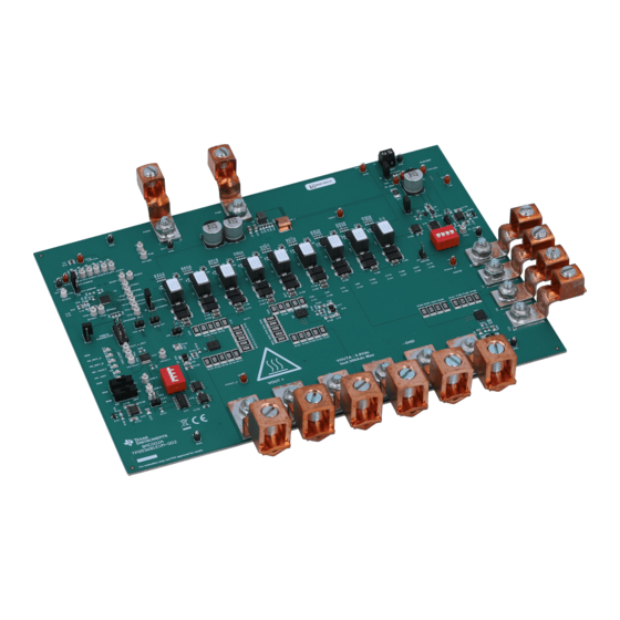
Using the TPS53681EVM-002, Dual Multiphase DC-DC
Step-Down Analog Controller with PMBus™ Interface
This User Guide describes the evaluation module (EVM) for the TPS53681 analog power controller, a
driverless D-CAP+™ multiphase buck controller, which manages several high current phases of the
CSD95490, a NexFet™ Smart Synchronous Buck Power Stage.
....................................................................................................................
1
2
2.1
3
.....................................................................................................................
4
...................................................................................................................
5
5.1
5.2
5.3
6
6.1
7
7.1
7.2
7.3
7.4
7.5
7.6
8
9
10
..................................................................................................................
11
1
Description
The TPS53681EVM implements a typical application for a low-voltage, high current dual output power
converter, operating from a nominal 12-V input rail to produce a 0.9-V output rail at up to 294 A of load
current and a 0.8-V rail at up to 47 A. The EVM includes test points for evaluating the performance of the
TPS53681 controller and CSD95490 power stages.
For ease of evaluation, the EVM requires only one (12-V) input supply and an output load to get started
with testing, however the user can opt to independently provide 5-V for greater control over the Power
Stage voltage. With the addition of the Fusion Digital Power™ Designer software, the EVM's PMBus™
interface allows access to the controller NVM for evaluation of additional configuration, control and
monitoring possibilities. Refer to the TPS53681 datasheet (SLUSCT1) for complete information on
configuring multi-phase operation with this controller.
SLUUBP7 - December 2017
Submit Documentation Feedback
.........................................................................................................
..............................................................................................................
.....................................................................................
................................................................................
....................................................................................................
.......................................................................................
..............................................................................
.........................................................................................
.............................................................................................................
...........................................................................................
.............................................................................
............................................................................
...........................................................................................................
..............................................................................
..................................................................................................
.............................................................................................................
Using the TPS53681EVM-002, Dual Multiphase DC-DC Step-Down Analog
Copyright © 2017, Texas Instruments Incorporated
.............................................
.................................................................
Controller with PMBus™ Interface
SLUUBP7 - December 2017
1
2
2
3
4
12
12
12
13
14
14
14
14
15
16
16
17
18
19
24
26
30
1
Advertisement
Table of Contents

Related Manuals for Texas Instruments TPS53681EVM-002


Summary of Contents for Texas Instruments TPS53681EVM-002
-
Page 1: Table Of Contents
Refer to the TPS53681 datasheet (SLUSCT1) for complete information on configuring multi-phase operation with this controller. SLUUBP7 – December 2017 Using the TPS53681EVM-002, Dual Multiphase DC-DC Step-Down Analog Controller with PMBus™ Interface Submit Documentation Feedback Copyright © 2017, Texas Instruments Incorporated... -
Page 2: Typical Applications
– Monitoring of input & output voltage, current, power, and power stage temperature • Convenient test points for probing critical waveforms Using the TPS53681EVM-002, Dual Multiphase DC-DC Step-Down Analog SLUUBP7 – December 2017 Controller with PMBus™ Interface Submit Documentation Feedback... -
Page 3: Electrical Performance Specifications
Rail B Full-load efficiency = 12 V, I = 47 A 90.6% OUTB Operating temperature ºC SLUUBP7 – December 2017 Using the TPS53681EVM-002, Dual Multiphase DC-DC Step-Down Analog Controller with PMBus™ Interface Submit Documentation Feedback Copyright © 2017, Texas Instruments Incorporated... -
Page 4: Schematic
Schematic www.ti.com Schematic Figure 1. TPS53681EVM - Controller Schematic Using the TPS53681EVM-002, Dual Multiphase DC-DC Step-Down Analog SLUUBP7 – December 2017 Controller with PMBus™ Interface Submit Documentation Feedback Copyright © 2017, Texas Instruments Incorporated... - Page 5 Schematic www.ti.com Figure 2. TPS53681EVM - Rail A Power Stages 1-3-5 Schematic SLUUBP7 – December 2017 Using the TPS53681EVM-002, Dual Multiphase DC-DC Step-Down Analog Controller with PMBus™ Interface Submit Documentation Feedback Copyright © 2017, Texas Instruments Incorporated...
- Page 6 Schematic www.ti.com Figure 3. TPS53681EVM - Rail A Power Stages 2-4-6 Schematic Using the TPS53681EVM-002, Dual Multiphase DC-DC Step-Down Analog SLUUBP7 – December 2017 Controller with PMBus™ Interface Submit Documentation Feedback Copyright © 2017, Texas Instruments Incorporated...
- Page 7 Schematic www.ti.com Figure 4. TPS53681EVM - Rail B Power Stages Schematic SLUUBP7 – December 2017 Using the TPS53681EVM-002, Dual Multiphase DC-DC Step-Down Analog Controller with PMBus™ Interface Submit Documentation Feedback Copyright © 2017, Texas Instruments Incorporated...
- Page 8 Schematic www.ti.com Figure 5. TPS53681EVM - AUX Voltages Schematic Using the TPS53681EVM-002, Dual Multiphase DC-DC Step-Down Analog SLUUBP7 – December 2017 Controller with PMBus™ Interface Submit Documentation Feedback Copyright © 2017, Texas Instruments Incorporated...
- Page 9 Schematic www.ti.com Figure 6. TPS53681EVM - Helper Circuits and Indicators Schematic SLUUBP7 – December 2017 Using the TPS53681EVM-002, Dual Multiphase DC-DC Step-Down Analog Controller with PMBus™ Interface Submit Documentation Feedback Copyright © 2017, Texas Instruments Incorporated...
- Page 10 Schematic www.ti.com Figure 7. TPS53681EVM - Input and Output Filter Schematic Using the TPS53681EVM-002, Dual Multiphase DC-DC Step-Down Analog SLUUBP7 – December 2017 Controller with PMBus™ Interface Submit Documentation Feedback Copyright © 2017, Texas Instruments Incorporated...
- Page 11 Schematic www.ti.com Figure 8. TPS53681EVM - On Board Transient Load Schematic SLUUBP7 – December 2017 Using the TPS53681EVM-002, Dual Multiphase DC-DC Step-Down Analog Controller with PMBus™ Interface Submit Documentation Feedback Copyright © 2017, Texas Instruments Incorporated...
-
Page 12: Test Setup
5.2.6 USB-to-GPIO Interface Adapter A communications adapter is required between the EVM and the host computer. This EVM is designed to use the Texas Instruments USB-to-GPIO adapter connected to J12. To purchase this adapter visit the TI USB-to_GPIO tool page. -
Page 13: Recommended Test Setup
12VIN 5VIN* VOUTB+ *IF EXTERNAL VOUTA+ SOURCE IS USED Figure 9. TPS53681EVM Recommended Test Setup SLUUBP7 – December 2017 Using the TPS53681EVM-002, Dual Multiphase DC-DC Step-Down Analog Controller with PMBus™ Interface Submit Documentation Feedback Copyright © 2017, Texas Instruments Incorporated... -
Page 14: Evm Configuration Using The Fusion Gui
10. Change relevant switch to OFF position (S1 for Rail A, S2 for Rail B). 11. Decrease VIN to 0 V. 12. Shut down the external fan if in use. Using the TPS53681EVM-002, Dual Multiphase DC-DC Step-Down Analog SLUUBP7 – December 2017 Controller with PMBus™ Interface Submit Documentation Feedback Copyright ©... -
Page 15: High Current Operation
=294A Figure 10. Thermal Picture of TPS53681 EVM. Rail A with Full Load Cooled at 100CFM SLUUBP7 – December 2017 Using the TPS53681EVM-002, Dual Multiphase DC-DC Step-Down Analog Controller with PMBus™ Interface Submit Documentation Feedback Copyright © 2017, Texas Instruments Incorporated... -
Page 16: Multiphase/Multi-Rail Configurations
4. To best observe transient effects, measure voltage across J16 (J17 for Rail B) 5. Turn OFF S3 (or S4) when finished observing transient effects. 6. Disconnect J14 (or J15) or turn off signal generator output. Using the TPS53681EVM-002, Dual Multiphase DC-DC Step-Down Analog SLUUBP7 – December 2017 Controller with PMBus™ Interface Submit Documentation Feedback Copyright ©... -
Page 17: Efficiency
VOUT Figure 11. Test Setup for Efficiency Measurement SLUUBP7 – December 2017 Using the TPS53681EVM-002, Dual Multiphase DC-DC Step-Down Analog Controller with PMBus™ Interface Submit Documentation Feedback Copyright © 2017, Texas Instruments Incorporated... -
Page 18: Equipment Turn-On And Shutdown
3. Reduce input voltage to 0 V and shut down input power supply VIN, then 5VIN if used. 4. Shut down the external fan if in use. Using the TPS53681EVM-002, Dual Multiphase DC-DC Step-Down Analog SLUUBP7 – December 2017 Controller with PMBus™ Interface Submit Documentation Feedback Copyright ©... -
Page 19: Performance Data And Typical Characteristic Curves
VOUT = 0.8 V, VIN =12 V Figure 14. VOUT A Load Regulation Figure 15. VOUT B Load Regulation SLUUBP7 – December 2017 Using the TPS53681EVM-002, Dual Multiphase DC-DC Step-Down Analog Controller with PMBus™ Interface Submit Documentation Feedback Copyright © 2017, Texas Instruments Incorporated... - Page 20 VIN = 12 V VOUT = 0.8 V IOUT = 45 A Figure 16. VOUT A Bode Plot Figure 17. VOUT B Bode Plot Using the TPS53681EVM-002, Dual Multiphase DC-DC Step-Down Analog SLUUBP7 – December 2017 Controller with PMBus™ Interface Submit Documentation Feedback Copyright ©...
- Page 21 Figure 21. VOUT A Output Ripple to 150 A to 0 A, 500 A/µs Slew Rate) SLUUBP7 – December 2017 Using the TPS53681EVM-002, Dual Multiphase DC-DC Step-Down Analog Controller with PMBus™ Interface Submit Documentation Feedback Copyright © 2017, Texas Instruments Incorporated...
- Page 22 Figure 25. VOUT B Transient Response (Load Step 45 A to 45 A, 500 A/µs Slew Rate) to 0 A, 500 A/µs Slew Rate) Using the TPS53681EVM-002, Dual Multiphase DC-DC Step-Down Analog SLUUBP7 – December 2017 Controller with PMBus™ Interface Submit Documentation Feedback Copyright ©...
- Page 23 VIN = 12 V, VOUT = 0.8 V, IOUT = 6 A Figure 28. VOUT B Enable Startup Figure 29. VOUT B Enable Shutdown SLUUBP7 – December 2017 Using the TPS53681EVM-002, Dual Multiphase DC-DC Step-Down Analog Controller with PMBus™ Interface Submit Documentation Feedback Copyright © 2017, Texas Instruments Incorporated...
-
Page 24: Evm Assembly Drawing
Figure 33. Internal Layer 1 (Top View) Figure 34. Internal Layer 2 (Top View) Figure 35. Internal Layer 3 (Top View) Using the TPS53681EVM-002, Dual Multiphase DC-DC Step-Down Analog SLUUBP7 – December 2017 Controller with PMBus™ Interface Submit Documentation Feedback... - Page 25 Figure 39. Internal Layer 7 (Top View) Figure 40. Internal Layer 8 (Top View) Figure 41. Bottom Copper (Top View) SLUUBP7 – December 2017 Using the TPS53681EVM-002, Dual Multiphase DC-DC Step-Down Analog Controller with PMBus™ Interface Submit Documentation Feedback Copyright © 2017, Texas Instruments Incorporated...
-
Page 26: Bill Of Materials
Kemet 0603 CAP, CERM, 0.01 uF, 100 V, +/- 5%, C176, C181 08051C103JAT2A X7R, 0805 Using the TPS53681EVM-002, Dual Multiphase DC-DC Step-Down Analog SLUUBP7 – December 2017 Controller with PMBus™ Interface Submit Documentation Feedback Copyright © 2017, Texas Instruments Incorporated... - Page 27 RES, 10.0, 1%, 0.063 W, 0402 CRCW040210R0FKED Vishay-Dale CRCW20101R00JNEFH RES, 1.0, 5%, 1 W, 2010 Vishay-Dale SLUUBP7 – December 2017 Using the TPS53681EVM-002, Dual Multiphase DC-DC Step-Down Analog Controller with PMBus™ Interface Submit Documentation Feedback Copyright © 2017, Texas Instruments Incorporated...
- Page 28 Test Point, Compact, White, TH 5007 Keystone TP39, TP40, TP41, TP42, TP43, TP44, TP52, TP53, TP57 Using the TPS53681EVM-002, Dual Multiphase DC-DC Step-Down Analog SLUUBP7 – December 2017 Controller with PMBus™ Interface Submit Documentation Feedback Copyright © 2017, Texas Instruments Incorporated...
- Page 29 R51, R57, R63, R69, R75, R81, R226, RES, 1.0, 5%, 0.1 W, 0603 CRCW06031R00JNEA Vishay-Dale R232, R238 SLUUBP7 – December 2017 Using the TPS53681EVM-002, Dual Multiphase DC-DC Step-Down Analog Controller with PMBus™ Interface Submit Documentation Feedback Copyright © 2017, Texas Instruments Incorporated...
-
Page 30: Fusion Gui
. If this were a power system that was populated with multiple Fusion GUI compatible devices, all of them would show up in the System View window. Figure 43. System View Using the TPS53681EVM-002, Dual Multiphase DC-DC Step-Down Analog SLUUBP7 – December 2017 Controller with PMBus™ Interface Submit Documentation Feedback Copyright ©... - Page 31 Fusion compatible devices connected as shown in Figure Figure 44. System Monitor SLUUBP7 – December 2017 Using the TPS53681EVM-002, Dual Multiphase DC-DC Step-Down Analog Controller with PMBus™ Interface Submit Documentation Feedback Copyright © 2017, Texas Instruments Incorporated...
- Page 32 To configure the these parameters on the other Rail, simply change options in the drop-down menu on the top- right corner. Figure 45. General Configure Tab Using the TPS53681EVM-002, Dual Multiphase DC-DC Step-Down Analog SLUUBP7 – December 2017 Controller with PMBus™ Interface Submit Documentation Feedback Copyright ©...
-
Page 33: Sluubp7 – December 2017 Using The Tps53681Evm-002, Dual Multiphase Dc-Dc Step-Down Analog
Fusion GUI www.ti.com Figure 46. Static Configure Tab SLUUBP7 – December 2017 Using the TPS53681EVM-002, Dual Multiphase DC-DC Step-Down Analog Controller with PMBus™ Interface Submit Documentation Feedback Copyright © 2017, Texas Instruments Incorporated... - Page 34 Fusion GUI www.ti.com Figure 47. Telemetry Configure Tab Figure 48. Transients Configure Tab Using the TPS53681EVM-002, Dual Multiphase DC-DC Step-Down Analog SLUUBP7 – December 2017 Controller with PMBus™ Interface Submit Documentation Feedback Copyright © 2017, Texas Instruments Incorporated...
- Page 35 Fusion GUI www.ti.com Figure 49. Protection Configure Tab SLUUBP7 – December 2017 Using the TPS53681EVM-002, Dual Multiphase DC-DC Step-Down Analog Controller with PMBus™ Interface Submit Documentation Feedback Copyright © 2017, Texas Instruments Incorporated...
- Page 36 This screen contains additional details such as the Hexadecimal encoding for the parameters. Figure 50. All Configure Using the TPS53681EVM-002, Dual Multiphase DC-DC Step-Down Analog SLUUBP7 – December 2017 Controller with PMBus™ Interface Submit Documentation Feedback...
- Page 37 If the user wishes to make this the new default value for the parameter then a [Store Config to NVM] must be performed, which commits the value to non-volatile memory. Figure 51. Static Configure Pop-Up SLUUBP7 – December 2017 Using the TPS53681EVM-002, Dual Multiphase DC-DC Step-Down Analog Controller with PMBus™ Interface Submit Documentation Feedback Copyright © 2017, Texas Instruments Incorporated...
- Page 38 • Margin control • Clear Fault clears any prior fault flags Figure 52. Monitor Screen Using the TPS53681EVM-002, Dual Multiphase DC-DC Step-Down Analog SLUUBP7 – December 2017 Controller with PMBus™ Interface Submit Documentation Feedback Copyright © 2017, Texas Instruments Incorporated...
- Page 39 Figure Figure 53. Status Screen SLUUBP7 – December 2017 Using the TPS53681EVM-002, Dual Multiphase DC-DC Step-Down Analog Controller with PMBus™ Interface Submit Documentation Feedback Copyright © 2017, Texas Instruments Incorporated...
- Page 40 Figure 54. Import Configuration File Using the TPS53681EVM-002, Dual Multiphase DC-DC Step-Down Analog SLUUBP7 – December 2017 Controller with PMBus™ Interface Submit Documentation Feedback...
- Page 41 STANDARD TERMS FOR EVALUATION MODULES Delivery: TI delivers TI evaluation boards, kits, or modules, including any accompanying demonstration software, components, and/or documentation which may be provided together or separately (collectively, an “EVM” or “EVMs”) to the User (“User”) in accordance with the terms set forth herein.
- Page 42 FCC Interference Statement for Class B EVM devices NOTE: This equipment has been tested and found to comply with the limits for a Class B digital device, pursuant to part 15 of the FCC Rules. These limits are designed to provide reasonable protection against harmful interference in a residential installation.
- Page 43 【無線電波を送信する製品の開発キットをお使いになる際の注意事項】 開発キットの中には技術基準適合証明を受けて いないものがあります。 技術適合証明を受けていないもののご使用に際しては、電波法遵守のため、以下のいずれかの 措置を取っていただく必要がありますのでご注意ください。 1. 電波法施行規則第6条第1項第1号に基づく平成18年3月28日総務省告示第173号で定められた電波暗室等の試験設備でご使用 いただく。 2. 実験局の免許を取得後ご使用いただく。 3. 技術基準適合証明を取得後ご使用いただく。 なお、本製品は、上記の「ご使用にあたっての注意」を譲渡先、移転先に通知しない限り、譲渡、移転できないものとします。 上記を遵守頂けない場合は、電波法の罰則が適用される可能性があることをご留意ください。 日本テキサス・イ ンスツルメンツ株式会社 東京都新宿区西新宿6丁目24番1号 西新宿三井ビル 3.3.3 Notice for EVMs for Power Line Communication: Please see http://www.tij.co.jp/lsds/ti_ja/general/eStore/notice_02.page 電力線搬送波通信についての開発キットをお使いになる際の注意事項については、次のところをご覧ください。http:/ /www.tij.co.jp/lsds/ti_ja/general/eStore/notice_02.page 3.4 European Union 3.4.1 For EVMs subject to EU Directive 2014/30/EU (Electromagnetic Compatibility Directive): This is a class A product intended for use in environments other than domestic environments that are connected to a low-voltage power-supply network that supplies buildings used for domestic purposes.
- Page 44 Notwithstanding the foregoing, any judgment may be enforced in any United States or foreign court, and TI may seek injunctive relief in any United States or foreign court. Mailing Address: Texas Instruments, Post Office Box 655303, Dallas, Texas 75265 Copyright © 2017, Texas Instruments Incorporated...
- Page 45 IMPORTANT NOTICE FOR TI DESIGN INFORMATION AND RESOURCES Texas Instruments Incorporated (‘TI”) technical, application or other design advice, services or information, including, but not limited to, reference designs and materials relating to evaluation modules, (collectively, “TI Resources”) are intended to assist designers who are developing applications that incorporate TI products;...
Need help?
Do you have a question about the TPS53681EVM-002 and is the answer not in the manual?
Questions and answers