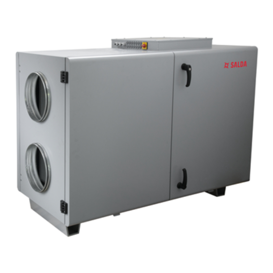
Salda RIRS EKO 3.0 1200 HE Mounting And Installation Instruction
Source: salda.lt/en, vetter-lufttechnik.de
Table of Contents
Advertisement
Advertisement
Table of Contents

Summarization of Contents
Symbols and Marking
Technical Label Information
Details and identification of components on the technical label.
Duct Connection Symbols
Explanation of symbols used for air duct connections (ODA, SUP, ETA, EHA).
Safety Instructions and Precautions
General Safety Rules
Key safety guidelines, warnings, and danger notices for installation and operation.
Package and Transportation
Unit Packaging and Palletization
Details on how the units are packaged and quantities per pallet.
Transportation and Unpacking Procedures
Instructions for safe handling during transport and unpacking.
Installation Requirements
Standard Components Included
List of standard parts included in the unit package.
Installation Space and Mounting
Requirements for installation space and mounting procedures.
Air Duct and Electrical Connections
Air Duct Connection Methods
Guidance on connecting circular and rectangular air ducts.
Electrical Connection Diagrams
Schematics for connecting the unit to the electrical network.
Start-Up and Maintenance
Pre-Startup Checks and Troubleshooting
Essential checks before operation and guidance for common faults.
Unit Maintenance Procedures
Detailed instructions for maintaining filters, fans, heat exchangers, and heaters.
Automatic Control and System Protection
Control Features and Modes
Description of Boost, Start/Stop, FanFail, continuous heating, cooling, and ventilation.
System Protection Mechanisms
Overview of safety features for water and electric heaters and antifreeze.
BMS Network and Modbus
BMS Network Integration
Instructions for connecting the unit to a Building Management System via ModBus.
Modbus Communication Addresses
Table listing Modbus addresses and their functions.
Electrical Unit Connection and Adjustment
HVAC Unit Electrical Connection
Guidelines for electrical connection of the unit and control panel.
System Adjustment Guidelines
Procedures for adjusting system parameters and settings.
Sensor and Converter Installation
Air Temperature and Quality Sensor Mounting
Recommendations for proper installation of temperature and air quality sensors.
Antifreeze Protection Installation
Proper installation of antifreeze protection for the water heater.
Control Board and Components
Control Board RG1 Overview
Information about the RG1 control board, including LED indications.
Component Labeling and Characteristics
Details on controller labeling and characteristics of system components.
Electrical Connection Diagrams
RIRS 1200 HE EKO 3.0 Electrical Diagram
Electrical schematic for the RIRS 1200 HE EKO 3.0 model.
RIRS 1900 HE EKO 3.0 Electrical Diagram
Electrical schematic for the RIRS 1900 HE EKO 3.0 model.
RIRS 1200-1900 HW EKO 3.0 Electrical Diagram
Electrical schematic for the RIRS 1200-1900 HW EKO 3.0 model.
RIRS 2500 HE EKO 3.0 Electrical Diagram
Electrical schematic for the RIRS 2500 HE EKO 3.0 model.
RIRS 2500 HW EKO 3.0 Electrical Diagram
Electrical schematic for the RIRS 2500 HW EKO 3.0 model.
RIRS 3500 HE EKO 3.0 Electrical Diagram
Electrical schematic for the RIRS 3500 HE EKO 3.0 model.
RIRS 3500 HW EKO 3.0 Electrical Diagram
Electrical schematic for the RIRS 3500 HW EKO 3.0 model.
RIRS 5500 HE EKO 3.0 Electrical Diagram
Electrical schematic for the RIRS 5500 HE EKO 3.0 model.
RIRS 5500 HW EKO 3.0 Electrical Diagram
Electrical schematic for the RIRS 5500 HW EKO 3.0 model.
Warranty and Maintenance Record
Warranty Terms and Conditions
Details on the warranty period, coverage, and exclusions.
Product Maintenance Log
A table for recording scheduled fan, heat exchanger, and filter maintenance.


Need help?
Do you have a question about the RIRS EKO 3.0 1200 HE and is the answer not in the manual?
Questions and answers