
Related Manuals for turck TBEN-L 8IOL Series


Summary of Contents for turck TBEN-L 8IOL Series
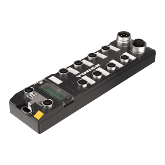
- Page 1 Your Global Automation Partner TBEN-L…-8IOL IO-Link Master Module Instructions for Use...
- Page 2 Hans Turck GmbH & Co. KG | T +49 208 4952-0 | F +49 208 4952-264 | more@turck.com | www.turck.com...
-
Page 3: Table Of Contents
Connecting the power supply .................. 23 7.2.1 Supply concept.......................... 24 Connecting IO-Link devices and digital sensors ............. 25 Commissioning .......................... 26 Setting the IP address.................... 26 8.1.1 Setting the IP address via switches at the device............... 26 8.1.2 Setting the IP address with Turck Service Tool .............. 28 V02.00 | 2019/10... - Page 4 Port functions for Port 0 (IO-Link Master)................ 121 10 Operating ............................ 126 10.1 Process input data...................... 126 10.2 Process output data .................... 128 10.3 LED displays......................... 129 Hans Turck GmbH & Co. KG | T +49 208 4952-0 | F +49 208 4952-264 | more@turck.com | www.turck.com...
- Page 5 10.4 Software diagnostic messages ................ 130 10.4.1 Status- and control word...................... 130 10.4.2 Diagnostic telegram........................ 131 10.4.3 PROFINET diagnostics ....................... 133 10.5 Using the data storage mode................... 136 10.5.1 Parameter ”data storage mode” = activated .............. 136 10.5.2 Parameter ”data storage mode” = read in ................. 138 10.5.3 Parameter ”data storage mode”...
- Page 6 Table of Contents Hans Turck GmbH & Co. KG | T +49 208 4952-0 | F +49 208 4952-264 | more@turck.com | www.turck.com...
-
Page 7: About These Instructions
This symbol denotes actions that the user must carry out. RESULTS OF ACTION This symbol denotes relevant results of actions. Additional documents The following additional documents are available online at www.turck.com: Data sheet EU Declaration of Conformity Commissioning manual IO-Link devices... -
Page 8: Notes On The Product
For further inquiries in Germany contact the Sales and Service Team on: Sales: +49 208 4952-380 Technology: +49 208 4952-390 Outside Germany, please contact your local Turck representative. Hans Turck GmbH & Co. KG | T +49 208 4952-0 | F +49 208 4952-264 | more@turck.com | www.turck.com... -
Page 9: For Your Safety
The product is designed according to state-of-the-art technology. However, residual risks still exist. Observe the following warnings and safety notices to prevent damage to persons and property. Turck accepts no liability for damage caused by failure to observe these warning and safety notices. -
Page 10: System Description Io-Link
Parallel exchange of device data without influencing the process data Communication via 24 V pulse modulation, standard UART protocol Hans Turck GmbH & Co. KG | T +49 208 4952-0 | F +49 208 4952-264 | more@turck.com | www.turck.com... -
Page 11: System Architecture
System architecture At least one IO-Link master and one IO-Link device (e.g. sensor or actuator) are required for IO- Link communication. IO-Link master and IO-Link device are interconnected via an unshielded 3- wire or 5-wire standard cable. The setting can be carried out with a configuration tool or via the fieldbus level. -
Page 12: Operating Principle
IO-Link device. Different minimum cycle times can be defined for different devices. Internal processing time of the IO-Link master and the IO-Link device Hans Turck GmbH & Co. KG | T +49 208 4952-0 | F +49 208 4952-264 | more@turck.com | www.turck.com... - Page 13 Cyclical and Acyclical Communication The data exchanged between IO-Link master and the IO-Link device can be divided into cyclical process data and acyclical data. Process data and value states are transferred cyclically. Acyc- lical data is transferred separately to cyclic process data. Acyclical data includes device data, parameter functions and events such as diagnostic information, which is only transferred on re- quest.
-
Page 14: Standard I/O Mode (Sio Mode)
In standard I/O mode IO-Link devices behave like digital sensors or actuators. In this mode the devices only send input or output data to the higher-level instance. IO-Link access to the device is not possible. Hans Turck GmbH & Co. KG | T +49 208 4952-0 | F +49 208 4952-264 | more@turck.com | www.turck.com... -
Page 15: Product Description
IO-Link mode or in SIO mode (DI). With Turck's "Simple IO-Link Device Integration (SIDI)", IO-Link devices can be directly integ- rated into PROFINET via the GSDML file of the TBEN-L…-8IOL. -
Page 16: Block Diagram
5 GND (V2) IO-Link Diag IO-Link 4 C/Q (V1) IO-Link Data IO-Link Ethernet µC IO-Link Diag Ethernet ETH1 ETH2 Fig. 6: Block diagram Hans Turck GmbH & Co. KG | T +49 208 4952-0 | F +49 208 4952-264 | more@turck.com | www.turck.com... -
Page 17: Properties And Features
Properties and features Fibre-glass reinforced housing Shock and vibration tested Fully potted module electronics Degree of protection IP67/IP69K UV-resistant according to DIN EN ISO 4892-2 Metal connectors 4 IO-Link ports Class A and 4 IO-Link ports Class B Multiprotocol functionality: PROFINET Device, EtherNet/IP™ Device, Modbus TCP Slave 4 universal DXP channels PROFINET: –... -
Page 18: Io-Link Channels
In all, up to four 3-wire PNP sensors or four PNP DC actuators with a maximum output current of 0.5 A can be connected per input or output. Hans Turck GmbH & Co. KG | T +49 208 4952-0 | F +49 208 4952-264 | more@turck.com | www.turck.com... -
Page 19: Mounting
Mounting The TBEN-L module can be screwed onto a flat mounting plate. „ Attach the module to the mounting surface with two M6 screws. The maximum tighten- ing torque for the screws is 1.5 Nm. „ Avoid mechanical stresses. „ Optional: Ground the device. -
Page 20: Grounding The Device
Fig. 8: TBEN-L4-8IOL equivalent circuit diagram and shielding concept 4 x 15 nF 1 nF 2,2 MΩ Fig. 9: TBEN-L5-8IOL equivalent circuit diagram and shielding concept Hans Turck GmbH & Co. KG | T +49 208 4952-0 | F +49 208 4952-264 | more@turck.com | www.turck.com... -
Page 21: Shielding Of The Fieldbus And I/O Level
6.2.2 Shielding of the fieldbus and I/O level The fieldbus and I/O module level of the TBEN-L modules can be grounded separately. Fig. 10: Grounding clip (1), grounding ring (2) and metal screw (3) The grounding ring (2) provides the grounding for the module. The shielding of the I/O level is permanently connected to the module ground. - Page 22 With the grounding clip mounted: The shield of the fieldbus is connected to the refer- ence potential of the installation via the module ground of the I/O level. Hans Turck GmbH & Co. KG | T +49 208 4952-0 | F +49 208 4952-264 | more@turck.com | www.turck.com...
-
Page 23: Connecting
Connecting Connecting the device to Ethernet For the connection to Ethernet the device has an integrated auto-crossing switch with two 4- pole, D-coded M12 x 1-Ethernet-connectors. The maximum tightening torque is 0.6 Nm. Fig. 14: M12 Ethernet connector „ Connect the device to Ethernet according to the pin assignment below. 1 = TX + 2 = RX + 3 = TX –... -
Page 24: Supply Concept
V1 = supply of the module electronics and the respective slots V2 = supply of module electronics and the respective connectors (separately detachable) Fig. 19: Supply TBEN-L…- 8IOL Hans Turck GmbH & Co. KG | T +49 208 4952-0 | F +49 208 4952-264 | more@turck.com | www.turck.com... -
Page 25: Connecting Io-Link Devices And Digital Sensors
Connecting IO-Link devices and digital sensors The device has eight M12 female connectors for connecting IO-Link devices and digital sensors and actuators. The maximum tightening torque is 0.8 Nm. NOTICE Wrong supply of IO-Link devices Damage to the device electronics „... -
Page 26: Commissioning
BootP server in the network. The subnet mask assigned by the BootP server and the default gateway address are stored non-volatile in the memory of the gateway. Hans Turck GmbH & Co. KG | T +49 208 4952-0 | F +49 208 4952-264 | more@turck.com | www.turck.com... - Page 27 In PGM mode, the complete IP address is assigned manually via the Turck Service Tool, FDT/DTM or via a web server. In PGM mode, the set IP address and the subnet mask are stored in the memory of the gate- way.
-
Page 28: Setting The Ip Address With Turck Service Tool
Fig. 25: Turck Service Tool – start dialog The Turck Service Tool shows the connected devices. Fig. 26: Turck Service Tool – found devices Hans Turck GmbH & Co. KG | T +49 208 4952-0 | F +49 208 4952-264 | more@turck.com | www.turck.com... - Page 29 „ Click on the desired device. „ Click Change or press [F2]. Fig. 27: Turck Service Tool – select the device to be addressed NOTE Clicking the IP address of the device opens the web server. „ Change the IP address and the network mask if necessary.
-
Page 30: Setting The Ip Address Via The Web Server
The ARGEE FLC programming software can be downloaded free of charge from www.turck.com The Zip archive "SW_ARGEE_Environment_Vx.x.zip" contains the software and the respective software documentation. Hans Turck GmbH & Co. KG | T +49 208 4952-0 | F +49 208 4952-264 | more@turck.com | www.turck.com... -
Page 31: Commissioning An Io-Link Device With Io-Link V1.0
Commissioning an IO-Link device with IO-Link V1.0 IO-Link devices in accordance with IO-Link specification V1.0 do not support data storage. If an IO-Link V1.0 device is used, data storage at the IO-Link port must be deactivated. „ Set Data storage mode at the port to deactivated, clear. „... -
Page 32: Commissioning An Io-Link Device With Io-Link V1.1
Fig. 31: Example: Reset device to factory settings via DTM „ Connect the IO-Link V1.1 device. The LED IOL at the IO-Link port is green, IO-Link communication active. Hans Turck GmbH & Co. KG | T +49 208 4952-0 | F +49 208 4952-264 | more@turck.com | www.turck.com... - Page 33 Delete the data storage memory via parameters „ Set Data storage mode to deactivated, clear. „ Load the parameter changes into the device. „ Re-activate the data storage, if necessary. „ Load the parameter changes into the device. „ Connect the IO-Link V1.1 device. The LED IOL at the IO-Link port is green, IO-Link communication active.
-
Page 34: Read In Connected Io-Link Devices: Topology Scan In The Dtm
Either the respective sensor DTMs in PACTware or the sensor IODDs via IODD DTM Configurator have to be installed. Fig. 33: PACTware – topology scan Hans Turck GmbH & Co. KG | T +49 208 4952-0 | F +49 208 4952-264 | more@turck.com | www.turck.com... -
Page 35: Commissioning The Device In Profinet
Commissioning the device in PROFINET 8.6.1 PROFINET IO device model The technical properties of PROFINET IO devices are defined via their device description file, the GSDML file. A PROFINET IO device consists of 1…n slots, which can also contain 1…n sub slots. Sub slots are placeholders for sub modules and establish the interface to the process. -
Page 36: Address Setting In Profinet
Assignment of a unique plant specific name to the respective field device. Assignment of the IP address from the IO-Controller before the system start-up based on the plant-specific (unique) name. Hans Turck GmbH & Co. KG | T +49 208 4952-0 | F +49 208 4952-264 | more@turck.com | www.turck.com... -
Page 37: Fsu - Fast Start-Up (Prioritized Startup)
PROFINET naming convention The names are assigned via DCP. The device name must meet the requirements of the Domain Name System (DNS) (see below). The device name is checked for correct spelling during input. NOTE The maximum length of the device name is 255 characters according to the specific- ation. - Page 38 45044 0xAFF4 I&M4-functions STRING[54] read/ I&M Signature write 45045… 0xAFF5 I&M5 to I&M15- not supported 45055 … functions 0xAFFF Hans Turck GmbH & Co. KG | T +49 208 4952-0 | F +49 208 4952-264 | more@turck.com | www.turck.com...
- Page 39 Acyclic I/O channel user data Index Name Data type Access Comment Dec. Hex. 0x01 Module paramet- specific read/ Parameters of the module write 0x02 Module type ENUM read Contains the module type UINT8 0x03 Module versio UINT8 read Firmware version of I/O channels 0x04 Module ID...
- Page 40 252 (0xFC) INDEX_CAP7 1 byte UINT8 253 (0xFD) INDEX_CAP8 1 byte UINT8 254 (0xFE) INDEX_CAP9 1 byte UINT8 255 (0xFF) Hans Turck GmbH & Co. KG | T +49 208 4952-0 | F +49 208 4952-264 | more@turck.com | www.turck.com...
-
Page 41: The Io-Link Function Block Iol_Call
8.6.7 The IO-Link function block IOL_CALL The IO-Link function block IOL_CALL is specified in the IO-Link specification "IO-Link Integration Part 1- Technical Specification for PROFIBUS and PROFINET“". Depending on the PLC manufacturer, the IO-Link CALL function block can differ from the specification (for example in the representation or the use of variables). - Page 42 Function not supported by IO-Link master. SUPPORTED 0xXX80AAXX MASTER_RESOURCE_ IO-Link master not available. UNAVAILABLE 0xXX80B0XX ACCESS_INVALID_INDEX Index invalid, wrong INDEX_CAP used Hans Turck GmbH & Co. KG | T +49 208 4952-0 | F +49 208 4952-264 | more@turck.com | www.turck.com...
- Page 43 Status Code Name Meaning 0xXX80B1XX ACCESS_WRITE_ Length of data to be written can not be LENGTH_ERROR handled from the module, wrong module ac- cessed. 0xXX80B2XX ACCESS_INVALID_ Wrong slot accessed DESTINATION 0xXX80B03XX ACCESS_TYPE_CONFLICT IOL_CALL invalid 0xXX80B5XX ACCESS_INVALID_INDEX Error in IOL_CALL sequence 0xXX80B6XX ACCESS_DENIED IOL-Link master module refuses the access.
- Page 44 Inconsistent parameters 0x8082 APP_DEVNOTRDY Application not ready, device busy 0x8100 UNSPECIFIC Vendor specific, according to device documentation 0x8101… VENDOR_SPECIFIC 0x8FF Hans Turck GmbH & Co. KG | T +49 208 4952-0 | F +49 208 4952-264 | more@turck.com | www.turck.com...
-
Page 45: Connecting The Device To A Siemens Plc In Profinet
– Port 1: Turck temperature sensor, TS-530-LI2UPN8X-..., IO-Link V1.0 – Port 2: Channel used as DI – Port 3: Turck linear position sensor, Li100P0-Q25LM0-..., IO-Link V1.0 – Port 4: Channel used as DI – Port 5: Channel used as DI –... -
Page 46: Installing The Gsdml File
Installing the GSDML-file: Define the source path for the GSDML-file and click Install. The device is added to the Hardware catalog of the programming software. Fig. 37: Installing the GSDML-file Hans Turck GmbH & Co. KG | T +49 208 4952-0 | F +49 208 4952-264 | more@turck.com | www.turck.com... -
Page 47: Connecting The Devices To The Plc
8.7.2 Connecting the devices to the PLC „ Select the TBEN-…-8IOL from the Hardware catalog and drag them into the "Device & networks" editor. „ Connect the devices to the PLC in the "Devices & networks" editor. Fig. 38: Connecting the device to the PLC V02.00 | 2019/10... -
Page 48: Assigning The Profinet Device Name
Assign PROFINET device name. „ Assign the desired PROFINET device name with Assign name. Fig. 39: Assigning the PROFINET device name Hans Turck GmbH & Co. KG | T +49 208 4952-0 | F +49 208 4952-264 | more@turck.com | www.turck.com... -
Page 49: Setting The Ip Address In Tia Portal
The function of the twelve empty slots is already defined in the GSDML file. The slots can only be used for a specific purpose. Slot Meaning Main module turck-tben-l5-8iol (default name) Parameterization of functions (protocol deactivation, etc.), which concern the complete module. Parameterization of PROFINET functions (MRP, etc.) X1 P1 Parameterization of the Ethernet port properties (topology, connection op- tions etc.). - Page 50 The IO-Link port is configured as digital input only. Port 8 4 byte IN Turck inclinometer, Port-configuration specific: B2N360-Q42-..., B2N360-Q42-E2LiUPN8X2 Hans Turck GmbH & Co. KG | T +49 208 4952-0 | F +49 208 4952-264 | more@turck.com | www.turck.com...
- Page 51 Ò „ Select Device view Device overview. „ Select functions as operation mode, diagnostics etc. from the hardware catalog and add them to the device slots via drag&drop. Fig. 41: TIA-Portal – configuring device slots V02.00 | 2019/10...
- Page 52 Select the device to be parameterized. Ò Ò „ Click Properties General Module parameters. „ Set the device parameters. Fig. 42: TIA-Portal – Parametrieren generischer IO-Link-Devices Hans Turck GmbH & Co. KG | T +49 208 4952-0 | F +49 208 4952-264 | more@turck.com | www.turck.com...
-
Page 53: Going Online With The Plc
8.7.6 Going online with the PLC „ Start the online mode (Go online). The device has been successfully connected to the PLC. Fig. 43: Starting the online mode 8.7.7 PROFINET – mapping The PROFINET mapping corresponds to the data mapping described in the sections "Process In- put Data”... -
Page 54: Use The Io_Link_Device Function Block In Tia Portal
Portal V15, the old IOL_CALL function block can be used to access the port 0 func- tions. Siemens provides the function block for TIA-Portal users under https://support.industry.siemens.com. Hans Turck GmbH & Co. KG | T +49 208 4952-0 | F +49 208 4952-264 | more@turck.com | www.turck.com... - Page 55 Start address of the input data of the IO-Link master e.g. with CPU 315 Fig. 45: Hardware identifier: Basic slot of the TBEN-L…-8IOL in the example Example read access – read product name Reading out the product name (product name, index 0x12) of the TURCK IO-Link I/O-hub TBIL- M1-16DXP at IO-Link port 4. „...
- Page 56 Fig. 46: IO_LINK_DEVICE – input variables for read access „ Activate the read access via a rising edge at REQ. Fig. 47: IO_LINK_DEVICE – activate read access Hans Turck GmbH & Co. KG | T +49 208 4952-0 | F +49 208 4952-264 | more@turck.com | www.turck.com...
- Page 57 In this example, the result of this request can be seen in the watch table (row 19 and fol- lowing) in the IO-Link Record. Fig. 48: IO_LINK_DEVICE – product name TBIL-M1-16DXP V02.00 | 2019/10...
- Page 58 0x05 = 600 ms measured value update time, display rotated by 180°. Fig. 49: Extract from the documentation for TS-500-… Hans Turck GmbH & Co. KG | T +49 208 4952-0 | F +49 208 4952-264 | more@turck.com | www.turck.com...
- Page 59 „ Write the input variables of the function block via control variable as follows: „ Activate the write access in the function block via RD_WR Sensor 1= TRUE. Variable True Meaning TRUE Send a write request Hardware identifier of the Basic slot according to the configuration in the Device view Function block instance Length of the data to be written [byte]...
- Page 60 Fig. 52: IO_LINK_DEVICE – activate read access The display is now rotated about 180° and set to an actualization time of 600 ms Hans Turck GmbH & Co. KG | T +49 208 4952-0 | F +49 208 4952-264 | more@turck.com | www.turck.com...
-
Page 61: Commissioning The Device In Modbus Tcp
Commissioning the device in Modbus TCP 8.8.1 Implemented Modbus functions The devices support the following functions for accessing process data, parameters, dia- gnostics and other services. Function codes Read Coils – reading multiple output bits Read Discrete Inputs – reading multiple input bits Read Holding Registers –... - Page 62 0x9000, 0x9001 36864, 36865 436865, 436866 Diagnostics 0xA000, 0xA001 40960, 40961 440961, 440962 Parameters 0xB000, 0xB001 45056, 45057 445057, 445058 Hans Turck GmbH & Co. KG | T +49 208 4952-0 | F +49 208 4952-264 | more@turck.com | www.turck.com...
- Page 63 Register 0x1130: Modbus connection mode This register defines the behavior of the Modbus connections. Designation Value Meaning MB_OnlyOneWritePermis- All Modbus connections receive the write au- sion thorization Only one Modbus connection can receive the write permission. A write permission is opened until a Disconnect.
-
Page 64: Data Width
The parameters are saved. 8.8.3 Data width Module Process input data Process output data Alignment TBEN-L…-8IOL 344 byte word by word Hans Turck GmbH & Co. KG | T +49 208 4952-0 | F +49 208 4952-264 | more@turck.com | www.turck.com... -
Page 65: Register Mapping
8.8.4 Register mapping Register Bit no. Input data 0x0000… Process input data 0x00xx [} 126] Module status 0x00xx see status- and control word + 1 re- [} 130] gister Output data 0x0800… Process output data 0x08xx [} 128] Diagnostics [} 130] 0xA000 DXP channel diagnostics 0xA001 IO-Link channel diagnosis …... - Page 66 VAUX1 monitoring 0xB048 VAUX2 VAUX2 pin2 pin2 C5 C4 (ch9) (ch11) 0xB049 VAUX2 VAUX2 pin2 pin2 C7 C6 (ch13) (ch15) Hans Turck GmbH & Co. KG | T +49 208 4952-0 | F +49 208 4952-264 | more@turck.com | www.turck.com...
-
Page 67: Error Behavior (Watchdog)
Input assembly instance 103, 120, 121, 122, 123,124, 125 Output assembly instance 104, 150, 151, 152 Configuration assembly Instance 8.9.2 EDS files and catalog files The EDS and catalog files can be downloaded free of charge from www.turck.com. TBEN-L_ETHERNETIP.zip V02.00 | 2019/10... -
Page 68: Device Level Ring (Dlr)
Communications Adapter 12 0x0C 0x03 Product UINT Identifier for a specific product of a code device type. default: 27247 = 6A6F Hans Turck GmbH & Co. KG | T +49 208 4952-0 | F +49 208 4952-264 | more@turck.com | www.turck.com... - Page 69 Attr. no. Attribute Get/Set Type Value name 0x04 Revision STRUCT OF: Revision of the device which is rep- resented by the Indentity Object. 0x01 Major USINT 0x06 Minor USINT 0x05 Device WORD WORD status 0x06 Serial UDINT Contains the ident no. of the product number (3 last bytes of the MAC-ID).
- Page 70 Starts the reset service for the device. 0x0E Get_Attribute_Single Returns the contents of a specified attribute. 0x10 Set_Attribute_Single Modifies a single attribute. Hans Turck GmbH & Co. KG | T +49 208 4952-0 | F +49 208 4952-264 | more@turck.com | www.turck.com...
- Page 71 The following description of the Ethernet Link Object is taken from the CIP specification, Vol. 2, Rev. 2.1 by ODVA & ControlNet International Ltd. and adapted to the Turck products. Instance attributes Attr.
- Page 72 IP™ con- sembly nection Instance Size [8 Instance Size [8 Instance Size [8 Rockwell Omron bit] bit] bit] IOL 8 IN/8 Hans Turck GmbH & Co. KG | T +49 208 4952-0 | F +49 208 4952-264 | more@turck.com | www.turck.com...
- Page 73 Configuration assembly (instance 106) The modules support Configuration Assembly. The Configuration Assembly contains: 10 bytes module configuration data (EtherNet/IP™-specific) + 136 bytes (parameter data, depending on device) The meaning of the input data can be found in chapter “Parameterizing and configuring”. Byte no.
- Page 74 [byte] puts [byte] gnostics (byte] nection [byte] [byte] Instance Size [8 bit] Exclusive Owner Input Only 103 Exclusive Owner (Omron) Hans Turck GmbH & Co. KG | T +49 208 4952-0 | F +49 208 4952-264 | more@turck.com | www.turck.com...
- Page 75 EtherNet/ Input Assembly Device Basic I/O IO-Link in- Dia- Event data IP™ Con- status [byte] puts [byte] gnostics (byte] nection [byte] [byte] Instance Size [8 bit] IOL 4 IN/4 OUT, dia- gnostics IOL 6 IN/6 OUT, dia- gnostics IOL 8 IN/8 OUT, dia- gnostics IOL 4 IN/4...
- Page 76 0xAB Port 16th Event) Qualifier (16th Event) 0xAC Event Code low byte (16th Event) Event Code high byte (16th Event) Hans Turck GmbH & Co. KG | T +49 208 4952-0 | F +49 208 4952-264 | more@turck.com | www.turck.com...
- Page 77 Instance 120 – 4 byte IN/4 byte OUT, diagnostics The description of the input data can be found in chapter “Operating” [} 126] Word Bit no. Status word 0x00 Diag Inputs 0x01 DI14 DI12 DI10 DXP7 DI6 DXP5 DI4 DXP3 DI2 DXP1 DI0 (SIO) (SIO)
- Page 78 DVS6 - DVS4 - DVS2 - DVS0 IO-Link process input data 0x03… 2 words per port 0x04 … 0x11… 0x12 Hans Turck GmbH & Co. KG | T +49 208 4952-0 | F +49 208 4952-264 | more@turck.com | www.turck.com...
- Page 79 Instance 122 – 6 byte IN/6 byte OUT, diagnostics The description of the input data can be found in chapter “Operating” [} 126] Word Bit no. Status word 0x00 Diag Inputs 0x01 DI14 DI12 DI10 DXP7 DI6 DXP5 DI4 DXP3 DI2 DXP1 DI0 (SIO) (SIO)
- Page 80 DVS6 - DVS4 - DVS2 - DVS0 IO-Link process input data 0x03… 3 words per port 0x05 … 0x18… 0x1A Hans Turck GmbH & Co. KG | T +49 208 4952-0 | F +49 208 4952-264 | more@turck.com | www.turck.com...
- Page 81 Instance 124 – 8 byte IN/8 byte OUT, diagnostics The description of the input data can be found in chapter “Operating” [} 126] Word Bit no. Status word 0x00 Diag Inputs 0x01 DI14 DI12 DI10 DXP7 DI6 DXP5 DI4 DXP3 DI2 DXP1 DI0 (SIO) (SIO)
- Page 82 - - - - DXP7 - DXP5 - DXP3 DXP1 IO-Link process output data 0x02… 16 words per port 0x11 … 0x72… 0x81 Hans Turck GmbH & Co. KG | T +49 208 4952-0 | F +49 208 4952-264 | more@turck.com | www.turck.com...
- Page 83 Word Bit no. 11 10 9 8 7 VAUX1/VAUX2 0x83 VAUX VAUX VAUX VAUX - - - - VAUX VAUX VAUX VAUX VAUX1 VAUX1 VAUX1 VAUX1 2 pin2 2 pin2 2 pin2 2 pin2 1 pin1 1 pin1 1 pin1 1 pin1 pin1 pin1...
- Page 84 1 pin1 1 pin1 pin1 pin1 pin1 pin1 (ch15) (ch13) (ch11) (ch9) (ch14) (ch12) (ch10) (ch8) (ch6/7) (ch4/5) (ch2/3) (ch0/1) Hans Turck GmbH & Co. KG | T +49 208 4952-0 | F +49 208 4952-264 | more@turck.com | www.turck.com...
- Page 85 Instance 152 – 8 byte IN/8 byte OUT The description of the output data can be found in chapter “Operating” [} 128] Word Bit no. 11 10 9 8 7 Control Word 0x00 reserved DXP outputs 0x01 - - - - DXP7 - DXP5 - DXP3 DXP1...
- Page 86 Common services Service code Class Instance Meaning Dec. Hex. 0x54 FWD_OPEN_CMD (opens a connection) 0x4E FWD_CLOSE_CMD (closes a connection) 0x52 UNCONNECTED_SEND_CMD Hans Turck GmbH & Co. KG | T +49 208 4952-0 | F +49 208 4952-264 | more@turck.com | www.turck.com...
- Page 87 TCP/IP Interface Object (0xF5) The following description of the Ethernet Link Object is taken from the CIP specification, Vol. 2, Rev. 1.1 by ODVA & ControlNet International Ltd. and adapted to the Turck products. Class attributes Attr. no. Designation Get/Set...
- Page 88 1 = The Interface Configuration attribute contains valid configuration. 2…15 = reserved 4…31 reserved Fig. 53: TCP/IP object state diagram (acc. to CIP Spec., Vol.2, Rev. 1.1) Hans Turck GmbH & Co. KG | T +49 208 4952-0 | F +49 208 4952-264 | more@turck.com | www.turck.com...
- Page 89 Configuration capability The Configuration capability indicates the device’s support for optional network configuration capability. Designation Meaning Value BOOTP client The device is capable of obtaining its network configuration via BOOTP. DNS client The device is capable of resolving host names by querying a DNS server.
- Page 90 2 = auto-negotiation failed but detected speed (de- fault: half duplex). 3 = successfully negotiated speed and duplex. 4 = autonegotiation not attempted. Forced speed and duplex. Hans Turck GmbH & Co. KG | T +49 208 4952-0 | F +49 208 4952-264 | more@turck.com | www.turck.com...
-
Page 91: Vsc-Vendor Specific Classes
Designation Meaning Default value Manual setting re- 0 = interface can activate changes to link paramet- quires reset ers (auto-negotiate, duplex mode, interface speed) automatically 1 = device requires a Reset service to be issued to its Identity Object in order to adapt the changes. Local Hardware 0 = interface detects no local hardware fault Fault... - Page 92 (cannot be deactivated via the EtherNet/IP™ interface). Bit 1: Deactivates Modbus TCP Bit 2: Deactivates PROFINET Bit 15: Deactivates the web server Hans Turck GmbH & Co. KG | T +49 208 4952-0 | F +49 208 4952-264 | more@turck.com | www.turck.com...
- Page 93 IO-Link Parameter Object (VSC 103) The IO-Link Parameter Object enables the acyclic transfer of parameter data between the IO- Link master and the IO-Link device. Instance 1 of the object addresses the IO-Link master The instance attribute numbers address the IO-Link port at the IO-Link master or the port 0 functions of the IO-Link master.
- Page 94 MSB from index of the IO-Link ISDU object acc. to IODD Data byte 2 Sub index USINT Sub index from the IO-Link ISDU object acc. to IODD Hans Turck GmbH & Co. KG | T +49 208 4952-0 | F +49 208 4952-264 | more@turck.com | www.turck.com...
- Page 95 Data Value/content Description Data byte 3…data Data Array of Byte Parameter data (n= length of ISDU object byte n + 3) V02.00 | 2019/10...
- Page 96 Meaning acc. to spe- cification 0x0000 No error No error 0x7000 IOL_CALL Unexpected Conflict write-re- quest, read request ex- pected Hans Turck GmbH & Co. KG | T +49 208 4952-0 | F +49 208 4952-264 | more@turck.com | www.turck.com...
- Page 97 Error code Designation Meaning acc. to spe- cification 0x7001 Wrong Decoding er- IOL_CALL 0x7002 Port blocked The accessed port is occu- pied by an- other task … reserved 0x8000 Timeout Timeout, IOL master or IOL device port busy 0x8001 Wrong index Error: IOL in- dex <...
- Page 98 Inconsistent parameters 0x8082 APP_DEVNOTRDY Application not ready, device busy 0x8100 UNSPECIFIC Vendor specific, according to device documenta- tion 0x8101… VENDOR_SPECIFIC 0x8FF Hans Turck GmbH & Co. KG | T +49 208 4952-0 | F +49 208 4952-264 | more@turck.com | www.turck.com...
- Page 99 IO-Link Port Class (VSC 137) This class provides one instance per IO-Link port at the IO-Link master module. Attr. no. Designation Get/ Type Meaning Dec. Hex. Parameters 0x01 Operation mode G/S USINT 0 = IO-Link without validation 1 = IO-Link with family compatible device 2 = IO-Link with compatible device 3 = IO-Link with identical device 4 = DI (with parameter access)
- Page 100 0x2B Input data word 15 USINT 0x2C Output data word 0 USINT … … … USINT 0x3B Output data word 15 USINT Hans Turck GmbH & Co. KG | T +49 208 4952-0 | F +49 208 4952-264 | more@turck.com | www.turck.com...
- Page 101 IO-Link Events Class (VSC 138) Attr. no. Designation Get/Set Type Meaning Dec. Hex. 0x01 IOL-Event 1 – port G USINT Port no. of the port which sends the 1st IO-Link Event. … … 0x10 IOL-Event 16 – USINT Port no. of the port which sends the port 16th IO-Link Event.
- Page 102 0x22 DXP 3 – Output value USINT 0x23 DXP 5 – Output value USINT 0x24 DXP 7 – Output value USINT Hans Turck GmbH & Co. KG | T +49 208 4952-0 | F +49 208 4952-264 | more@turck.com | www.turck.com...
- Page 103 VAUX Control Class (VSC 161) This class contains parameters and diagnostics for the monitoring of 24 VDC sensor and actu- ator supply. Attr.-no. Designation Get/ Type Meaning Dec. Hex. Activate VAUX1 monitoring 0x01 VAUX Control - VAUX1 pin1 C0 (ch0/1) G/S USINT 0 = 24 VDC 1 = switchable...
- Page 104 0 = off 1 = on 0x18 VAUX Control - VAUX2 pin2 C7 (ch15) G USINT 0 = off 1 = on Hans Turck GmbH & Co. KG | T +49 208 4952-0 | F +49 208 4952-264 | more@turck.com | www.turck.com...
-
Page 105: Connecting The Devices To A Rockwell Plc With Ethernet/Ip
Used Software The following software tools are used in this example: Rockwell RS Logix Catalog file for Turck compact stations "TURCK_BLOCK_STATIONS_Vxx.L5K" as part of the file "TBEN-L_ETHERNETIP.zip" (downloadable free of charge under www.turck.com) Catalog files Turck provides catalog files "TURCK_BLOCK_STATIONS_Vxx.L5K" for use in Rockwell Automa- tion's RSLogix/Studio5000. -
Page 106: Adding The Devices From The Catalog Files To The New Project
8.10.1 Adding the devices from the catalog files to the new project „ Right-click the device entry and use Copy. Fig. 54: RSLogix – Copying the device entry from catalog file Hans Turck GmbH & Co. KG | T +49 208 4952-0 | F +49 208 4952-264 | more@turck.com | www.turck.com... - Page 107 „ Right-click the EtherNet/IP™-Scanner in the second instance of the RS Logix and add the device to the project via Paste. In this example, the configuration with 4 byte in- and 4 byte output data plus diagnostics TBEN_L5_8IOL_4in4out_diag is used. Fig. 55: RSLogix –...
-
Page 108: Configuring The Device In Rs Logix
Set the IP address of the device. Fig. 56: Setting module name and IP address „ Optional: Set the connection parameters Fig. 57: Setting the connection parameters Hans Turck GmbH & Co. KG | T +49 208 4952-0 | F +49 208 4952-264 | more@turck.com | www.turck.com... -
Page 109: Parameterizing The Device
8.10.3 Parameterizing the device „ Open the Controller Tags of the device. „ Parameterize the device via the Controller Tags (in the example: TBEN_L5_8IOL_4in- 4out_diag:C). Fig. 58: Parameterizing the Device V02.00 | 2019/10... -
Page 110: Going Online With The Plc
Set the communication path via Set Project Path. The communication path is set. Fig. 59: Setting the communication path „ Select the PLC. „ Click Go online. Hans Turck GmbH & Co. KG | T +49 208 4952-0 | F +49 208 4952-264 | more@turck.com | www.turck.com... - Page 111 Fig. 60: Going online with the device „ Click Download In the following dialog (Connect To Go Online) „ Confirm all following messages. The project is loaded down to the controller. The connection is established. V02.00 | 2019/10...
-
Page 112: Reading Process Data
The access to parameter data (TBEN_L5_8IOL_…:C), input data (TBEN_L5_8IOL_…:I) and output data (TBEN_L5_8IOL_…:O) is possible. Fig. 61: Controller Tags in the project tree Hans Turck GmbH & Co. KG | T +49 208 4952-0 | F +49 208 4952-264 | more@turck.com | www.turck.com... -
Page 113: Parameters
Parameterizing and Configuring Parameters The device has 4 bytes of module parameters, 16 bytes each of IO-Link port parameters and 16 bytes of parameters for VAUX1/VAUX2 monitoring. Word no. Bit no. Basic 0x00 DXP7_ DXP5_ DXP3_ DXP1_ 0x01 DXP7_ DXP5_ DXP3_ DXP1_ EN DO... - Page 114 The device remains in the safe state (Pre-Operate). Parameters and diagnostic information can be read and respectively written. Hans Turck GmbH & Co. KG | T +49 208 4952-0 | F +49 208 4952-264 | more@turck.com | www.turck.com...
- Page 115 Parameter name Value Meaning Description dec. Hex. 0x02 IO-Link with compatible Pin 4 is operated in IO-Link mode. device The master checks if the Vendor ID and the Device ID of the connected device match those of the con- figured one. If the Vendor ID matches, but the Device ID not, then the master tries to write the Device ID to the device.
- Page 116 (Mapping PDIN) the fieldbus side. PROFINET: With PROFINET, the parameter is permanently set to 0x00 = direct and cannot be changed. Hans Turck GmbH & Co. KG | T +49 208 4952-0 | F +49 208 4952-264 | more@turck.com | www.turck.com...
- Page 117 Parameter name Value Meaning Description dec. Hex. 0x00 direct The process data are not swapped. i.e.: 0x0123 4567 89AB CDEF 0x01 Swap 16 bit The bytes are swapped per word. i.e.: 0x2301 6745 AB89 EFCD 0x02 Swap 32 bit The bytes are swapped per double word. i.e.: 0x6745 2301 EFCD AB89 0x03 swap all All bytes are swapped.
- Page 118 0x54 29.6 0x7A 57.6 0x90 0xA3 118.4 0xB6 15.2 1x56 30.4 0x7C 59.2 0x91 89.6 0xA4 0xB7 auto., 0xFF comp. Hans Turck GmbH & Co. KG | T +49 208 4952-0 | F +49 208 4952-264 | more@turck.com | www.turck.com...
-
Page 119: Adapting Process Data Mapping
9.1.1 Adapting process data mapping The mapping of process data can be adapted application-specifically via the IO-Link master's parameterization. Depending on the used fieldbus, it can be necessary to swap process data word-wise, double word-wise or completely in order to align them to the data structure in the PLC. The process data mapping is determined channel by channel through the parameters process input data mapping and process output data mapping. -
Page 120: Profinet Parameters
Entity_Port 0 = IO-Link master module (IOLM) Entity_Port 1 = IO-Link device at IO-Link port 1 … Entity_Port 8 = IO-Link device at IO-Link port 8 Hans Turck GmbH & Co. KG | T +49 208 4952-0 | F +49 208 4952-264 | more@turck.com | www.turck.com... -
Page 121: Port Functions For Port 0 (Io-Link Master)
9.2.1 Port functions for Port 0 (IO-Link Master) IO-Link Index (port function invocation) The access to the IO-Link master functionalities (port 0) is done via index 65535: Subindex 64: Master Port Validation Configuration The object writes a specific configuration of the Devices to be connected to the IO-Link port to the Master. - Page 122 Defines the type of the event (Warning, Noti- fication, Single Shot Event, etc.) in accordance with IO-Link specification „IO-Link Interface and System“. Hans Turck GmbH & Co. KG | T +49 208 4952-0 | F +49 208 4952-264 | more@turck.com | www.turck.com...
- Page 123 Byte no. Bit no. Description Port IO-Link port which sends an event Event Code high byte High or- low byte of the error code sent Event Code low byte … … Qualifier see byte 2 - 5 Port Event Code high byte Event Code low byte Subindex 66: Set Default Parameterization Writing this object sets the IO-Link master back to factory settings.
- Page 124 Diagnostic bit Meaning NO_DS The parameterized port mode does not support data storage. Remedy: Change the parameterization of the port. Hans Turck GmbH & Co. KG | T +49 208 4952-0 | F +49 208 4952-264 | more@turck.com | www.turck.com...
- Page 125 Diagnostic bit Meaning DS_F Error in the data storage, synchronization not possible Possible causes: Connected device does not support data storage Overflow of the data storage buffer Remedy: „ Connect a device that supports data storage. „ Clear the data storage buffer. „...
-
Page 126: Process Input Data
0x83 - DXP 7 DXP 5 DXP 3 DXP 1 IO-Link port 1 0x84 GEN- OVL V EVT1 EVT2 PD HIGH Hans Turck GmbH & Co. KG | T +49 208 4952-0 | F +49 208 4952-264 | more@turck.com | www.turck.com... - Page 127 Word Bit no. 11 10 0x85 IO-Link port 2, assignment similar to port 1 0x86 IO-Link port 3, assignment similar to port 1 0x87 IO-Link port 4, assignment similar to port 1 0x88 IO-Link port 5, assignment similar to port 1 0x89 IO-Link port 6, assignment similar to port 1 0x8A IO-Link port 7, assignment similar to port 1 0x8B IO-Link port 8, assignment similar to port 1...
-
Page 128: Process Output Data
The 24 VDC sensor/actuator supply at Pin1 of the connector is Cx (chy/chz) switched off. The 24 VDC sensor/actuator supply at Pin1 of the connector is switched on. Hans Turck GmbH & Co. KG | T +49 208 4952-0 | F +49 208 4952-264 | more@turck.com | www.turck.com... -
Page 129: Led Displays
Name Value Meaning VAUX2 Pin2 The Class B supply at Pin2 of the connector is switched off. Cx (chy/chz) The Class B supply at Pin2 of the connector is switched on. 10.3 LED displays The device has the following LED indicators: Power supply Group and bus errors Status... -
Page 130: Software Diagnostic Messages
DIAG Byte 1 Byte 0 Description Internal error The device-internal communication is dis- turbed. DIAG Diagnostic messages at the device Hans Turck GmbH & Co. KG | T +49 208 4952-0 | F +49 208 4952-264 | more@turck.com | www.turck.com... -
Page 131: Diagnostic Telegram
Description The DTM Force Mode is activated, which means, the actual output values may no match the ones defined and sent by the field bus. V1 or V2 too low (< 18 V DC). The status word is mapped into the module's process data. In EtherNet/IP™... - Page 132 IO-Link device. EVT1 Maintenance events A Maintenance event in accordance with the IO-Link specification occurred, maintenance necessary. Hans Turck GmbH & Co. KG | T +49 208 4952-0 | F +49 208 4952-264 | more@turck.com | www.turck.com...
-
Page 133: Profinet Diagnostics
Meaning EVT2 Out-of-specification events An Out-of-specification event in accordance with the IO-Link specification oc- curred. GENERR Common error The device sends an error (device status 4, in accordance with IO-Link specifica- tion), which is not clearly specified. Read out the device Event Codes in order to be able to specify the error more precisely. - Page 134 IO-Link port 5 (Slot 6, according to configuration tool) Similar to port 1 IO-Link port 6 (Slot 7, according to configuration tool) Hans Turck GmbH & Co. KG | T +49 208 4952-0 | F +49 208 4952-264 | more@turck.com | www.turck.com...
- Page 135 IO-Link port diagnostics PROFINET Diagnostics Similar to port 1 IO-Link port 7 (Slot 8, according to configuration tool) Similar to port 1 IO-Link port 8 (Slot 9, according to configuration tool) Similar to port 1 V02.00 | 2019/10...
-
Page 136: Using The Data Storage Mode
The data set in the device is actual, if DS_UPLOAD_FLAG = 1. The data set in the Master is actual, if DS_UPLOAD_FLAG = 0. Hans Turck GmbH & Co. KG | T +49 208 4952-0 | F +49 208 4952-264 | more@turck.com | www.turck.com... - Page 137 IO-Link master. Turck IO-Link devices can be reset to factory settings via a system command using a generic IO-Link-DTM and the device-specific IODD. For the reset of third party devices, please read the corresponding manufacturer documentation.
-
Page 138: Parameter "Data Storage Mode" = Read In
The data set in the master is deleted. The synchronization of parameter sets is deactivated. IOLM IOLD Fig. 68: Data storage mode deactivated – no synchronization Hans Turck GmbH & Co. KG | T +49 208 4952-0 | F +49 208 4952-264 | more@turck.com | www.turck.com... -
Page 139: Troubleshooting
Troubleshooting If the device does not work as expected, proceed as follows: „ Exclude environmental disturbances. „ Check the connections of the device for errors. „ Check device for parameterization errors. If the malfunction persists, the device is faulty. In this case, decommission the device and re- place it with a new device of the same type. -
Page 140: Maintenance
Example: update the firmware with the PACTware™ FDT frame application „ Launch PACTware™. Ò „ Right-click Host PC Add device. Fig. 69: Adding a Device in PACTware™ Hans Turck GmbH & Co. KG | T +49 208 4952-0 | F +49 208 4952-264 | more@turck.com | www.turck.com... - Page 141 „ Select BL Service Ethernet and confirm with OK. Fig. 70: Selecting the Ethernet interface „ Double-click the connected device. PACTware™ opens the bus address management. Fig. 71: Opening the busaddress management V02.00 | 2019/10...
- Page 142 PACTware™ shows the progress of the firmware update with a green bar at the bottom of the screen. Fig. 74: Firmware update in progress Hans Turck GmbH & Co. KG | T +49 208 4952-0 | F +49 208 4952-264 | more@turck.com | www.turck.com...
-
Page 143: Repair
Observe our return acceptance conditions when returning the device to Turck. 13.1 Returning devices Returns to Turck can only be accepted if the device has been equipped with a Decontamination declaration enclosed. The decontamination declaration can be downloaded from https://www.turck.de/en/retoure-service-6079.php and must be completely filled in, and affixed securely and weather-proof to the outside of the packaging. -
Page 144: Technical Data
Address assignment Static IP, DHCP Supported Function Codes FC1, FC2, FC3, FC4, FC5, FC6, FC15, FC16, FC23 Number of TCP connections Hans Turck GmbH & Co. KG | T +49 208 4952-0 | F +49 208 4952-264 | more@turck.com | www.turck.com... - Page 145 Technical Data Register start address 0 (0x0000) Register start address 2048 (0x0800) Lokal port Port 502, fixed setting EtherNet/IP™ Address assignment according to EtherNet/IP™ standard Device Level Ring (DLR) Supported Quick Connect (QC) < 150 ms Number of Class 3 (TCP) connec- tions Number of Class 1 (CIP) connec- tions...
- Page 146 160 years acc. to SN 29500 (Ed. 99) 20 °C Housing material PA6-GF30 Housing color Black Material window Lexan Material label Polycarbonate Halogen-free Hans Turck GmbH & Co. KG | T +49 208 4952-0 | F +49 208 4952-264 | more@turck.com | www.turck.com...
- Page 147 FCC declaration NOTE This equipment has been tested and found to comply with the limits for a Class A digital device, pursuant to part 15 of the FCC Rules. These limits are designed to provide reasonable protection against harmful interference when the equipment is operated in a commercial environment.
- Page 148 Over 30 subsidiaries and over 60 representations worldwide! D301407 | 2019/10 D301407 www.turck.com...
Need help?
Do you have a question about the TBEN-L 8IOL Series and is the answer not in the manual?
Questions and answers