Advertisement
Quick Links
Advertisement

Related Manuals for turck TBEN-LL-8IOL


Summary of Contents for turck TBEN-LL-8IOL
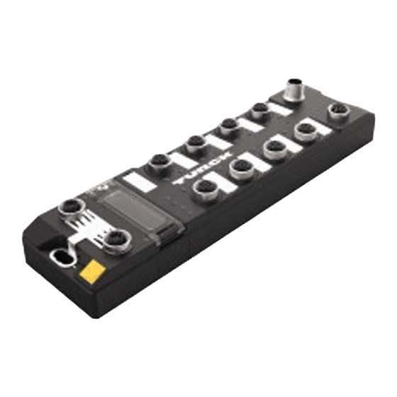
- Page 1 Your Global Automation Partner TBEN-LL-8IOL IO-Link Master Module Instructions for Use...
- Page 2 Hans Turck GmbH & Co. KG | T +49 208 4952-0 | F +49 208 4952-264 | more@turck.com | www.turck.com...
- Page 3 Connecting the power supply .................. 24 7.2.1 Supply concept.......................... 25 Connecting IO-Link devices and digital sensors ............. 26 Commissioning .......................... 28 Setting the IP address.................... 28 8.1.1 Setting the IP address via switches at the device............... 28 8.1.2 Setting the IP address with Turck Service Tool .............. 30 V01.00 | 2019/11...
- Page 4 Port functions for Port 0 (IO-Link Master)................ 122 10 Operating ............................ 127 10.1 Process input data...................... 127 10.2 Process output data .................... 129 10.3 LED displays......................... 130 Hans Turck GmbH & Co. KG | T +49 208 4952-0 | F +49 208 4952-264 | more@turck.com | www.turck.com...
- Page 5 10.4 Software diagnostic messages ................ 131 10.4.1 Status- and control word...................... 132 10.4.2 Diagnostic telegram........................ 133 10.4.3 PROFINET diagnostics ....................... 135 10.5 Using the data storage mode................... 137 10.5.1 Parameter ”data storage mode” = activated .............. 137 10.5.2 Parameter ”data storage mode” = read in ................. 139 10.5.3 Parameter ”data storage mode”...
- Page 6 Table of Contents Hans Turck GmbH & Co. KG | T +49 208 4952-0 | F +49 208 4952-264 | more@turck.com | www.turck.com...
- Page 7 This symbol denotes actions that the user must carry out. RESULTS OF ACTION This symbol denotes relevant results of actions. Additional documents The following additional documents are available online at www.turck.com: Data sheet EU Declaration of Conformity Commissioning manual IO-Link devices...
- Page 8 For further inquiries in Germany contact the Sales and Service Team on: Sales: +49 208 4952-380 Technology: +49 208 4952-390 Outside Germany, please contact your local Turck representative. Hans Turck GmbH & Co. KG | T +49 208 4952-0 | F +49 208 4952-264 | more@turck.com | www.turck.com...
- Page 9 The product is designed according to state-of-the-art technology. However, residual risks still exist. Observe the following warnings and safety notices to prevent damage to persons and property. Turck accepts no liability for damage caused by failure to observe these warning and safety notices.
- Page 10 Parallel exchange of device data without influencing the process data Communication via 24 V pulse modulation, standard UART protocol Hans Turck GmbH & Co. KG | T +49 208 4952-0 | F +49 208 4952-264 | more@turck.com | www.turck.com...
- Page 11 System architecture At least one IO-Link master and one IO-Link device (e.g. sensor or actuator) are required for IO- Link communication. IO-Link master and IO-Link device are interconnected via an unshielded 3- wire or 5-wire standard cable. The setting can be carried out with a configuration tool or via the fieldbus level.
- Page 12 IO-Link device. Different minimum cycle times can be defined for different devices. Internal processing time of the IO-Link master and the IO-Link device Hans Turck GmbH & Co. KG | T +49 208 4952-0 | F +49 208 4952-264 | more@turck.com | www.turck.com...
- Page 13 Cyclical and Acyclical Communication The data exchanged between IO-Link master and the IO-Link device can be divided into cyclical process data and acyclical data. Process data and value states are transferred cyclically. Acyc- lical data is transferred separately to cyclic process data. Acyclical data includes device data, parameter functions and events such as diagnostic information, which is only transferred on re- quest.
- Page 14 In standard I/O mode IO-Link devices behave like digital sensors or actuators. In this mode the devices only send input or output data to the higher-level instance. IO-Link access to the device is not possible. Hans Turck GmbH & Co. KG | T +49 208 4952-0 | F +49 208 4952-264 | more@turck.com | www.turck.com...
- Page 15 The devices are designed in a fully encapsulated housing with degree of protection IP65/IP67/ IP69K. The IO-Link master module TBEN-LL-8IOL has eight IO-Link ports for connecting IO-Link devices. The IO-Link ports at the connectors X0…X3 are designed as Class A ports. The IO-Link ports at the connectors X4…X7 are designed as Class B ports.
- Page 16 – Network load class 3 EtherNet/IP: – Support of the IO-Link Parameter Object for asynchronous services (IO-Link CALL) – Predefined in- and oputput assemblies Hans Turck GmbH & Co. KG | T +49 208 4952-0 | F +49 208 4952-264 | more@turck.com | www.turck.com...
- Page 17 Device Level Ring (DLR) 5.4.2 IO-Link channels The IO-Link master module TBEN-LL-8IOL has four Class A IO-Link ports (slots X0…X3) and four Class B IO-Link ports (slots X4…X7). The eight IO-Link channels can be parameterized independently of each other and operated either in IO-Link mode or in SIO mode (DI).
- Page 18 In all, up to four 3-wire PNP sensors or four PNP DC actuators with a maximum output current of 0.5 A can be connected per input or output. Hans Turck GmbH & Co. KG | T +49 208 4952-0 | F +49 208 4952-264 | more@turck.com | www.turck.com...
- Page 19 Mounting NOTICE Mounting on uneven surfaces Device damage due to stresses in the housing „ Fix the device on a flat mounting surface. „ Use two M6 screws for mounting. The device can be screwed onto a flat mounting plate. „...
- Page 20 Hans Turck GmbH & Co. KG | T +49 208 4952-0 | F +49 208 4952-264 | more@turck.com | www.turck.com...
- Page 21 Shielding concept of the fieldbus level On delivery, a grounding clip is provided on the connectors for the fieldbus connection. When mounted directly on a mounting plate, the shielding of the fieldbus cables is routed dir- ectly to the module ground via the grounding clip and the metal screw in the lower mounting hole.
- Page 22 With mounted grounding clip: The shielding of the fieldbus is connected to the reference potential of the installation via the module grounding of the I/O level. Hans Turck GmbH & Co. KG | T +49 208 4952-0 | F +49 208 4952-264 | more@turck.com | www.turck.com...
- Page 23 Connecting Connecting the device to Ethernet For the connection to Ethernet the device has an integrated auto-crossing switch with two 4- pole, D-coded M12 x 1-Ethernet-connectors. The maximum tightening torque is 0.6 Nm. Fig. 12: M12 Ethernet connector „ Connect the device to Ethernet according to the pin assignment below. 1 = TX 2 = RX 3 = TX...
- Page 24 LED PWR changes from green to red. In case of an undervoltage at V1, the LED PWR is turned off. Hans Turck GmbH & Co. KG | T +49 208 4952-0 | F +49 208 4952-264 | more@turck.com | www.turck.com...
- Page 25 V1 = supply of the module electronics and the respective slots V2 = supply of module electronics and the respective connectors (separately detachable) Fig. 16: Power supply of TBEN-LL-8IOL V01.00 | 2019/11...
- Page 26 3 = GND (V1) 4 = C/Q (V1) 5 = GND (V2) X4…X7 Fig. 19: Pin assignment of IO-Link master ports, Class B, X4…X7 Hans Turck GmbH & Co. KG | T +49 208 4952-0 | F +49 208 4952-264 | more@turck.com | www.turck.com...
- Page 27 „ Connect the sensors and actuators to the device according to the pin assignment. Meaning Pin 1 VAUX1, switchable via process data Pin 2 Switchable Class B supply (VAUX2) Pin 3 Ground V1 Pin 4 IO-Link or digital input Pin 5 Ground V2 NOTICE Connection of Class A devices to Class B ports...
- Page 28 Device damage through penetrating foreign objects or liquids is possible. Close the cover over the switches securely. Hans Turck GmbH & Co. KG | T +49 208 4952-0 | F +49 208 4952-264 | more@turck.com | www.turck.com...
- Page 29 PGM mode In PGM mode, the complete IP address is assigned manually via the Turck Service tool, FDT/DTM or via a web server. In PGM mode, the set IP address and the subnet mask are stored in the gateway memory. All network settings (IP address, subnet mask, default gateway) are accep- ted by the internal EEPROM of the module.
- Page 30 Fig. 21: Turck Service Tool – start dialog The Turck Service Tool shows the connected devices. Fig. 22: Turck Service Tool – found devices Hans Turck GmbH & Co. KG | T +49 208 4952-0 | F +49 208 4952-264 | more@turck.com | www.turck.com...
- Page 31 „ Click on the desired device. „ Click Change or press [F2]. Fig. 23: Turck Service Tool – select the device to be addressed NOTE Clicking the IP address of the device opens the web server. „ Change the IP address and the network mask if necessary.
- Page 32 Write the new IP address, subnet mask and default gateway via Submit to the device. Fig. 25: Setting the IP Address via the Web Server Hans Turck GmbH & Co. KG | T +49 208 4952-0 | F +49 208 4952-264 | more@turck.com | www.turck.com...
- Page 33 ARGEE/FLC The ARGEE FLC programming software can be downloaded free of charge from www.turck.com The Zip archive "SW_ARGEE_Environment_Vx.x.zip" contains the software and the respective software documentation. Commissioning an IO-Link device with IO-Link V1.0 IO-Link devices in accordance with IO-Link specification V1.0 do not support data storage. If an IO-Link V1.0 device is used, data storage at the IO-Link port must be deactivated.
- Page 34 Fig. 27: Example: Reset device to factory settings via DTM „ Connect the IO-Link V1.1 device. The LED IOL at the IO-Link port is green, IO-Link communication active. Hans Turck GmbH & Co. KG | T +49 208 4952-0 | F +49 208 4952-264 | more@turck.com | www.turck.com...
- Page 35 Delete the data storage memory via parameters „ Set Data storage mode to deactivated, clear. „ Load the parameter changes into the device. „ Re-activate the data storage, if necessary. „ Load the parameter changes into the device. „ Connect the IO-Link V1.1 device. The LED IOL at the IO-Link port is green, IO-Link communication active.
- Page 36 Either the respective sensor DTMs in PACTware or the sensor IODDs via IODD DTM Configurator have to be installed. Fig. 29: PACTware – topology scan Hans Turck GmbH & Co. KG | T +49 208 4952-0 | F +49 208 4952-264 | more@turck.com | www.turck.com...
- Page 37 Commissioning the device in PROFINET 8.6.1 PROFINET IO device model The technical properties of PROFINET IO devices are defined via their device description file, the GSDML file. A PROFINET IO device consists of 1…n slots, which can also contain 1…n sub slots. Sub slots are placeholders for sub modules and establish the interface to the process.
- Page 38 IO-Link ports for the configuration with specific IO-Link devices or for gen- eric configuration one slot each for diagnostics and status Hans Turck GmbH & Co. KG | T +49 208 4952-0 | F +49 208 4952-264 | more@turck.com | www.turck.com...
- Page 39 8.6.3 Address setting in PROFINET In IP-based communication, the field devices are addressed by means of an IP address. PROFINET uses the Discovery and Configuration Protocol (DCP) for IP assignment. When delivered, each field device has, among other things, a MAC address. The MAC address is sufficient to give the respective field device a unique name.
- Page 40 … 0xAFEF 45040 0xAFF0 I&M0-functions read Identification & Maintaining 45041 0xAFF1 I&M0-functions STRING[54] read/ I&M Tag function and write location Hans Turck GmbH & Co. KG | T +49 208 4952-0 | F +49 208 4952-264 | more@turck.com | www.turck.com...
- Page 41 Index Name Data type Access Comment 45042 0xAFF2 I&M2-functions STRING[16] read/ I&M Installation Date write 45043 0xAFF3 I&M3-functions STRING[54] read/ I&M Description Text write 45044 0xAFF4 I&M4-functions STRING[54] read/ I&M Signature write 45045… 0xAFF5 I&M5 to I&M15- not supported 45055 …...
- Page 42 0xFE CAP 8 Record read/ write 0xFF CAP 9 Record read/ Client access point for class 2 write masters Hans Turck GmbH & Co. KG | T +49 208 4952-0 | F +49 208 4952-264 | more@turck.com | www.turck.com...
- Page 43 IM99 (IOL_M) Name Size Data type Default setting IOL_LINK_VERSION 1 byte UINT8 17 (0x11) IO_LINK_PROFILE_VERSION 1 byte UINT8 0 (0x00) IO_LINK_FEATURE_SUPPORT 4 byte UINT32 0 (0x00) NUMBER_OF_PORTS 1 byte UINT8 4 (0x04) REF_PORT_CONFIG 1 byte UINT8 0 (0x00) REF_IO_MAPPING 1 byte UINT8 0 (0x00) REF_IOL_M...
- Page 44 Length of the data to be read/written. This information is not necessary for the Siemens IOL_CALL. RECORD_IOL_DATA Source/destination for the data to be read/written. Hans Turck GmbH & Co. KG | T +49 208 4952-0 | F +49 208 4952-264 | more@turck.com | www.turck.com...
- Page 45 IOL_CALL – output variables Designation Data type Meaning acc. IO-Link spec. DONE_VALID BOOL The read or write access has been executed. BUSY BOOL The read or write access is actually in progress. ERROR BOOL Error while reading or writing. STATUS DWORD Communication error status of the acyclic communication [} 45] IOL_STATUS DWORD...
- Page 46 M_ISDU_ILLEGAL Device can not respond to master request 0x8000 APP_DEV Application error in the device 0x8011 IDX_NOTAVAIL Index not available Hans Turck GmbH & Co. KG | T +49 208 4952-0 | F +49 208 4952-264 | more@turck.com | www.turck.com...
- Page 47 IOL-Error Type Designation acc. to IO-Link Spec. Meaning 0x8012 SUBIDX_NOTAVAIL Sub-Index not available 0x8020 SERV_NOTAVAIL The service is temporarily not available. 0x8021 SERV_NOTAVAIL_LOCCTRL Service temporarily not available, device is busy (e. g. teaching or parameterization of the device via the master active) 0x8022 SERV_NOTAVAIL_DEVCTRL Service temporarily not available, device is...
- Page 48 The programming software has been started. A new project has been created. The PLC has been added to the project. Hans Turck GmbH & Co. KG | T +49 208 4952-0 | F +49 208 4952-264 | more@turck.com | www.turck.com...
- Page 49 8.7.1 Installing the GSDML file The GSDML file can be downloaded for free from www.turck.com Ò „ Adding the GSDML-file: Click "Options" "Manage general station description files (GSD)". „ Installing the GSDML-file: Define the source path for the GSDML-file and click Install.
- Page 50 „ Connect the devices to the PLC in the "Devices & networks" editor. Fig. 34: Connecting the device to the PLC Hans Turck GmbH & Co. KG | T +49 208 4952-0 | F +49 208 4952-264 | more@turck.com | www.turck.com...
- Page 51 8.7.3 Assigning the PROFINET device name Ò „ Select Online access Online & diagnostics. Ò „ Functions Assign PROFINET device name. „ Assign the desired PROFINET device name with Assign name. Fig. 35: Assigning the PROFINET device name V01.00 | 2019/11...
- Page 52 Ò Ò „ Select Device view Properties Ethernet addresses. „ Assign the desired IP address. Fig. 36: Assigning the IP address Hans Turck GmbH & Co. KG | T +49 208 4952-0 | F +49 208 4952-264 | more@turck.com | www.turck.com...
- Page 53 8.7.5 Configuring device functions The TBEN-LL-8IOL appears as a modular slave with twelve empty virtual slots. Slots 0 and Basic are pre-configured. The function of the twelve empty slots is already defined in the GSDML file. The slots can only be used for a specific purpose.
- Page 54 Select functions as operation mode, diagnostics etc. from the hardware catalog and add them to the device slots via drag&drop. Fig. 37: TIA-Portal – configuring device slots Hans Turck GmbH & Co. KG | T +49 208 4952-0 | F +49 208 4952-264 | more@turck.com | www.turck.com...
- Page 55 Setting IO-Link Port Parameters In generic port configuration, the ports of the IO-Link master can be operated in IO-Link mode with different configuration as well as in SIO mode (DI). In specific port configuration, the IO-Link ports receive the parameters from the GSDML-file. Parameters like for example Operation mode, Data storage mode, Vendor- and Device ID can- not be changed.
- Page 56 The PROFINET mapping corresponds to the data mapping described in the sections "Process In- put Data” [} 127] and „Process Output Data" [} 129]. Hans Turck GmbH & Co. KG | T +49 208 4952-0 | F +49 208 4952-264 | more@turck.com | www.turck.com...
- Page 57 8.7.8 Use the IO_LINK_DEVICE function block in TIA Portal The IO_LINK_DEVICE function block is based on the IOL_CALL function block according to the IO-Link specification. Fig. 40: Example call of Siemens FB "IO_LINK_DEVICE" NOTE The access to the port 0 functions of the IO-Link master with an IOL_INDEX of 65535 is not possible with version V3.0.2 of the Siemens IO_LINK_DEVICE block.
- Page 58 Start address of the input data of the IO-Link master e.g. with CPU 315 Fig. 41: Hardware identifier: Basic slot of the TBEN-L…-8IOL in the example Hans Turck GmbH & Co. KG | T +49 208 4952-0 | F +49 208 4952-264 | more@turck.com | www.turck.com...
- Page 59 Example read access – read product name Reading out the product name (product name, index 0x12) of the TURCK IO-Link I/O-hub TBIL- M1-16DXP at IO-Link port 4. „ Write the input variables of the function block via control variable as follows:...
- Page 60 In this example, the result of this request can be seen in the watch table (row 19 and fol- lowing) in the IO-Link Record. Fig. 44: IO_LINK_DEVICE – product name TBIL-M1-16DXP Hans Turck GmbH & Co. KG | T +49 208 4952-0 | F +49 208 4952-264 | more@turck.com | www.turck.com...
- Page 61 Example access write – rotate display The display of the Turck temperature sensors TS-500-LUUPN8X-H1141-... at IO-Link port 1 is ro- tated. The parameter Measured value update time/rotating/disabling a display in index 55 is set to 0x05 = 600 ms measured value update time, display rotated by 180°.
- Page 62 1. IOL_INDEX 0x12 Index for Measured value update time/rotating/dis- abling a display Fig. 46: IO_LINK_DEVICE – input variables for read access Hans Turck GmbH & Co. KG | T +49 208 4952-0 | F +49 208 4952-264 | more@turck.com | www.turck.com...
- Page 63 „ Set the value to be written 0x05 via the first word of IO-Link Record in the watch table. Fig. 47: IO_LINK_DEVICE – Control value 0x05 for index 0x55 „ Activate the Write access via a rising edge at REQ. Fig. 48: IO_LINK_DEVICE – activate read access The display is now rotated about 180°...
- Page 64 Bit 0 = EtherNet/IP active Bit 1 = Modbus TCP active Bit 2 = PROFINET active Bit 15 = Web server active Hans Turck GmbH & Co. KG | T +49 208 4952-0 | F +49 208 4952-264 | more@turck.com | www.turck.com...
- Page 65 Address Access Meaning 0x1150 read only LED behavior (PWR) at V2 undervoltage bit 0: 0 = red 1 = green flashing 0x2400 read only V1 [mV]: 0 at < 18 V 0x2401 read only V2 [mV]: 0 at < 18 V 0x8000…0x8400 read only Process data of the inputs (identical to registers...
- Page 66 0x113D. Both registers can also be written with one single request using the function codes FC16 and FC23. The parameters are reset tot default values. „ Save changes via a subsequent Save service. Hans Turck GmbH & Co. KG | T +49 208 4952-0 | F +49 208 4952-264 | more@turck.com | www.turck.com...
- Page 67 Register 0x113E and 0x113F: Save Modbus-Connection-Parameters Registers 0x113E and 0x113F are used for the non-volatile saving of parameters in registers 0x1120 and 0x1130 to 0x113B. Procedure: „ Write 0x7361 to register 0×113E. „ Write 0x7665 ("save") within 30 seconds in register 0x113F to activate the reset of the re- gisters.
- Page 68 8 registers parameter data, assignment similar to port 1 0xB019 IO-Link port 4 0xB01A… 8 registers parameter data, assignment similar to port 1 0xB021 Hans Turck GmbH & Co. KG | T +49 208 4952-0 | F +49 208 4952-264 | more@turck.com | www.turck.com...
- Page 69 Register no. Bit no. 15 14 13 12 11 10 9 IO-Link port 5 0xB022… 8 registers parameter data, assignment similar to port 1 0xB029 IO-Link port 6 0xB02A… 8 registers parameter data, assignment similar to port 1 0xB031 IO-Link port 7 0xB032…...
- Page 70 8.9.2 EDS files and catalog files The EDS and catalog files can be downloaded free of charge from www.turck.com. TBEN-L_ETHERNETIP.zip Hans Turck GmbH & Co. KG | T +49 208 4952-0 | F +49 208 4952-264 | more@turck.com | www.turck.com...
- Page 71 8.9.3 Device Level Ring (DLR) The devices support DLR. The Device Level Ring (DLR)-redundancy protocol is used to increase the stability of EtherNet/IP networks. DLR-enabled devices have an integrated switch and can thus be integrated into a ring topology. The DLR protocol is used to detect an interruption in the ring.
- Page 72 = 0 Configured TRUE = 1: The application in the device has been con- figured (default setting). reserved default = 0 Hans Turck GmbH & Co. KG | T +49 208 4952-0 | F +49 208 4952-264 | more@turck.com | www.turck.com...
- Page 73 Name Definition 4…7 Extended Device Status 0011 = no I/O connection established 0110 = at least one I/O connection in RUN mode 0111 = at least one I/O connection established, all in IDLE mode All other settings = reserved Minor recoverable fault Recoverable fault, e.g.: Undervoltage Force-Mode in DTM active...
- Page 74 IOL 6 IN/6 OUT, diagnostics IOL 8 IN/8 OUT, diagnostics IOL 4 IN/4 OUT IOL 6 IN/6 OUT IOL 8 IN/8 OUT Hans Turck GmbH & Co. KG | T +49 208 4952-0 | F +49 208 4952-264 | more@turck.com | www.turck.com...
- Page 75 Configuration assembly (instance 106) The modules support Configuration Assembly. The Configuration Assembly contains: 10 bytes module configuration data (EtherNet/IP-specific) + 136 bytes (parameter data, depending on device) The meaning of the input data can be found in chapter “Parameterizing and configuring”. Byte no.
- Page 76 The port is set to autonegotiation. 100BT/FD Fix setting of the communication parameters for the Ethernet port to: 100BaseT full duplex Hans Turck GmbH & Co. KG | T +49 208 4952-0 | F +49 208 4952-264 | more@turck.com | www.turck.com...
- Page 77 Input assembly instances EtherNet/IP Con- Input Assembly Device Basic I/O IO-Link Diagnostics Event nection status [byte] inputs [byte] data [byte] [byte] (byte] Instance Size [8 bit] Exclusive Owner 103 Input Only Exclusive Owner (Omron) IOL 4 IN/4 OUT, diagnostics IOL 6 IN/6 OUT, diagnostics IOL 8 IN/8 OUT, diagnostics...
- Page 78 0xAB Port 16th Event) Qualifier (16th Event) 0xAC Event Code low byte (16th Event) Event Code high byte (16th Event) Hans Turck GmbH & Co. KG | T +49 208 4952-0 | F +49 208 4952-264 | more@turck.com | www.turck.com...
- Page 79 Instance 120 – 4 byte IN/4 byte OUT, diagnostics The description of the input data can be found in chapter “Operating” [} 127] Word Bit no. Status word 0x00 Diag Inputs 0x01 DI14 DI12 DI10 DXP7 DI6 DXP5 DI4 DXP3 DI2 DXP1 DI0 (SIO) (SIO)
- Page 80 DVS6 - DVS4 - DVS2 - DVS0 IO-Link process input data 0x03… 2 words per port 0x04 … 0x11… 0x12 Hans Turck GmbH & Co. KG | T +49 208 4952-0 | F +49 208 4952-264 | more@turck.com | www.turck.com...
- Page 81 Instance 122 – 6 byte IN/6 byte OUT, diagnostics The description of the input data can be found in chapter “Operating” [} 127] Word Bit no. Status word 0x00 Diag Inputs 0x01 DI14 DI12 DI10 DXP7 DI6 DXP5 DI4 DXP3 DI2 DXP1 DI0 (SIO) (SIO)
- Page 82 DVS6 - DVS4 - DVS2 - DVS0 IO-Link process input data 0x03… 3 words per port 0x05 … 0x18… 0x1A Hans Turck GmbH & Co. KG | T +49 208 4952-0 | F +49 208 4952-264 | more@turck.com | www.turck.com...
- Page 83 Instance 124 – 8 byte IN/8 byte OUT, diagnostics The description of the input data can be found in chapter “Operating” [} 127] Word Bit no. Status word 0x00 Diag Inputs 0x01 DI14 DI12 DI10 DXP7 DI6 DXP5 DI4 DXP3 DI2 DXP1 DI0 (SIO) (SIO)
- Page 84 DVS6 - DVS4 - DVS2 - DVS0 IO-Link process input data 0x03… 4 words per port 0x06 … 0x1F… 0x22 Hans Turck GmbH & Co. KG | T +49 208 4952-0 | F +49 208 4952-264 | more@turck.com | www.turck.com...
- Page 85 Output assembly instances EtherNet/IP Con- Output Assembly Control DXP outputs IO-Link VAUX [byte] nection word [byte] [byte] outputs [byte] Instance Size [8 bit] Exclusive Owner 104 IOL 4 IN/4 OUT IOL 6 IN/6 OUT IOL 8 IN/8 OUT Instance 104 – Exclusive Owner The description of the output data can be found in chapter “Operating”...
- Page 86 X3 pin1 X2 pin1 X1 pin1 X0 (ch14) (ch12) (ch10) (ch8) (ch6/7) (ch4/5) (ch2/3) (ch0/1) (ch15) (ch13) (ch11) (ch9) Hans Turck GmbH & Co. KG | T +49 208 4952-0 | F +49 208 4952-264 | more@turck.com | www.turck.com...
- Page 87 This object is used for connection and connectionless communications, including establishing connections across multiple subnets. The following description of the Ethernet Link Object is taken from the CIP specification, Vol. 2, Rev. 2.1 by ODVA & ControlNet International Ltd. and adapted to the Turck products. Common services Service code...
- Page 88 0x06 Host name String 0 = no host name con- figured 0x0C QuickConnect BOOL 0 = deactivate 1 = activate Hans Turck GmbH & Co. KG | T +49 208 4952-0 | F +49 208 4952-264 | more@turck.com | www.turck.com...
- Page 89 Common services Service code Class Instance Meaning Dec. Hex. 0x01 Get_Attribute_All 0x02 Set_Attribute_All 0x0E Get_Attribute_Single 0x10 Set_Attribute_Single Interface status This status attribute shows the status of the TCP/IP network interface. Refer to the TCP/IP Ob- ject Status Diagram for details on the states of this status attribute. Designation Meaning 0…3...
- Page 90 This mechanism allows the DHCP client to forward its host name to the DHCP servers. The DHCP server then updates the DNS data for the client. Hans Turck GmbH & Co. KG | T +49 208 4952-0 | F +49 208 4952-264 | more@turck.com | www.turck.com...
- Page 91 Ethernet Link Object (0xF6) The following description of the Ethernet Link Object is taken from the CIP specification, Vol. 2, Rev. 1.1 by ODVA & ControlNet International Ltd. and adapted to the Turck products. Class attributes Attr.-no. Designation Get/Set Type Value Dec.
- Page 92 Basic Class [} 101] Parameters and diagnostics of the digital channels channels 0xB9 VAUX Control Class [} 104] Parameters and status for VAUX Hans Turck GmbH & Co. KG | T +49 208 4952-0 | F +49 208 4952-264 | more@turck.com | www.turck.com...
- Page 93 Gateway Class (VSC 100) This class contains all information concerning the whole device. Object Instance 2, Gateway Instance Attr. no. Designation Get/set Type Meaning Dec. Hex. 0x6D Status word STRUCT The status word contains gen- (status register 2) eral module status information. 0x73 On IO connection ENUM...
- Page 94 MSB from index of the IO-Link ISDU object acc. to IODD Data byte 2 Sub index USINT Sub index from the IO-Link ISDU object acc. to IODD Hans Turck GmbH & Co. KG | T +49 208 4952-0 | F +49 208 4952-264 | more@turck.com | www.turck.com...
- Page 95 Request parameters for the ISDU Read Service Name Data type Description Data byte 0 0x12 UINT Index for the product name in the device (e.g. Turck I/O hub TBIL-M1-16DXP) according to IODD Data byte 1 0x00 UINT Data byte 2 0x00 USINT The index has no sub index.
- Page 96 IO-Link Parameter Object Instance 0x01 Addressing the IO-Link master Instance attribute 0x04 IO-Link port number Service code 0x4C Write_ISDU: Write access Hans Turck GmbH & Co. KG | T +49 208 4952-0 | F +49 208 4952-264 | more@turck.com | www.turck.com...
- Page 97 Request parameters for the ISDU write service Name Data type Description 0x18 UINT Index for the application specific tag in the device (e.g. In Turck I/O-Hub TBIL-M1- 16DXP) 0x00 USINT The index has no sub index. Byte 0: 0x54 The Application Specific Tag of the device...
- Page 98 0x04 Revision USINT 0 = automatic 1 = V 1.0 0x05 Activate USINT 0 = no Quick Start- 1 = yes Hans Turck GmbH & Co. KG | T +49 208 4952-0 | F +49 208 4952-264 | more@turck.com | www.turck.com...
- Page 99 Attr. no. Designation Get/ Type Meaning Dec. Hex. 0x06 Device para- USINT 0 = no meterization 1 = yes via GSD 0x07 Process input USINT 0 = diagnostics generated data invalid 1 = no diagnostic generated 0x08 Deactivate USINT 0 = no diagnostics 1 = notifications 2 = notifications and warnings...
- Page 100 Event code of the 1st IO-Link event Event Code … … 0x30 IOL-Event 16– USINT Event code of the 1st IO-Link event Event Code Hans Turck GmbH & Co. KG | T +49 208 4952-0 | F +49 208 4952-264 | more@turck.com | www.turck.com...
- Page 101 Basic Class (VSC 184) Attr. no. Designation Get/set Type Meaning Dec. Hex. 0x01 DXP 1 - Manual output reset after overcurrent G/S USINT 0 = no 1 = yes 0x02 DXP 3 - Manual output reset after overcurrent G/S USINT 0 = no 1 = yes 0x03...
- Page 102 USINT 0 = off 1 = on 0x2D DXP 1 – Output value USINT 0 = off 1 = on Hans Turck GmbH & Co. KG | T +49 208 4952-0 | F +49 208 4952-264 | more@turck.com | www.turck.com...
- Page 103 Attr. no. Designation Get/set Type Meaning Dec. Hex. 0x2E DXP 3 – Output value USINT 0 = off 1 = on 0x2F DXP 5 – Output value USINT 0 = off 1 = on 0x30 DXP 7 – Output value USINT 0 = off 1 = on...
- Page 104 0 = off 1 = on 0x0E VAUX Control - VAUX1 pin1 X1 (Ch2/3) USINT 0 = off 1 = on Hans Turck GmbH & Co. KG | T +49 208 4952-0 | F +49 208 4952-264 | more@turck.com | www.turck.com...
- Page 105 Attr. no. Designation Get/set Type Meaning Dec. Hex. 0x0F VAUX Control - VAUX1 pin1 X2 (Ch4/5) USINT 0 = off 1 = on 0x10 VAUX Control - VAUX1 pin1 X3 (Ch6/7) USINT 0 = off 1 = on 0x11 VAUX Control - VAUX1 pin1 X4 (Ch8) USINT 0 = off 1 = on...
- Page 106 The PLC and the Scanner mentioned above have been added to the project in the second in- stance of RSLogix/Studio5000. Hans Turck GmbH & Co. KG | T +49 208 4952-0 | F +49 208 4952-264 | more@turck.com | www.turck.com...
- Page 107 8.10.1 Adding the devices from the catalog files to the new project „ Right-click the device entry and use Copy. Fig. 50: RSLogix – Copying the device entry from catalog file V01.00 | 2019/11...
- Page 108 Paste. In this example, the configuration with 4 byte in- and 4 byte output data plus diagnostics TBEN_L5_8IOL_4in4out_diag is used. Fig. 51: RSLogix – predefined configurations of TBEN-L5-8IOL in new project Hans Turck GmbH & Co. KG | T +49 208 4952-0 | F +49 208 4952-264 | more@turck.com | www.turck.com...
- Page 109 8.10.2 Configuring the device in RS Logix „ Open the device entry by double-clicking. „ Assign a module name. „ Set the IP address of the device. Fig. 52: Setting module name and IP address „ Optional: Set the connection parameters Fig. 53: Setting the connection parameters V01.00 | 2019/11...
- Page 110 Open the Controller Tags of the device. „ Parameterize the device via the Controller Tags (in the example: TBEN_L5_8IOL_4in- 4out_diag:C). Fig. 54: Parameterizing the Device Hans Turck GmbH & Co. KG | T +49 208 4952-0 | F +49 208 4952-264 | more@turck.com | www.turck.com...
- Page 111 8.10.4 Going online with the PLC „ Search the network via the Who Active function. „ Select the PLC. „ Set the communication path via Set Project Path. The communication path is set. Fig. 55: Setting the communication path V01.00 | 2019/11...
- Page 112 Click Download In the following dialog (Connect To Go Online) „ Confirm all following messages. The project is loaded down to the controller. The connection is established. Hans Turck GmbH & Co. KG | T +49 208 4952-0 | F +49 208 4952-264 | more@turck.com | www.turck.com...
- Page 113 8.10.5 Reading process data „ Open the Controller Tags in the project tree by double-clicking the entry. The access to parameter data (TBEN_L5_8IOL_…:C), input data (TBEN_L5_8IOL_…:I) and output data (TBEN_L5_8IOL_…:O) is possible. Fig. 57: Controller Tags in the project tree V01.00 | 2019/11...
- Page 114 Assignment similar to IO-Link port 1 (Word 0x02...0x09) 0x31 IO-Link port 7 0x32… Assignment similar to IO-Link port 1 (Word 0x02...0x09) 0x39 Hans Turck GmbH & Co. KG | T +49 208 4952-0 | F +49 208 4952-264 | more@turck.com | www.turck.com...
- Page 115 Word no. Bit no. IO-Link port 8 0x3A… Assignment similar to IO-Link port 1 (Word 0x02...0x09) 0x41 VAUX monitoring 0x42 VAUX1 pin1 VAUX1 pin1 X1 (ch2/3) X0 (ch0/1) 0x43 VAUX1 pin1 VAUX1 pin1 X3 (ch6/7) X2 (ch4/5) 0x44 VAUX1 pin1 VAUX1 pin1 X5 (ch10) X4 (ch8)
- Page 116 (master or device) serve as the reference data. 0x01 overwrite Synchronization of parameter data activated, the data in the master serve as reference data. Hans Turck GmbH & Co. KG | T +49 208 4952-0 | F +49 208 4952-264 | more@turck.com | www.turck.com...
- Page 117 Parameter name Value Meaning Description dec. Hex. 0x02 read in Synchronization of parameter data activated. The data in the connected IO-Link device serve as refer- ence data. Synchronization of parameter data deactivated. The 0x03 Deactivated, clear data set in the master is deleted. Activate Quick For fast applications (e.g.
- Page 118 0x02 off The Class B supply at Pin2 of the respective connector is switched off. Hans Turck GmbH & Co. KG | T +49 208 4952-0 | F +49 208 4952-264 | more@turck.com | www.turck.com...
- Page 119 Values for the parameter ”cycle time” [ms]: Time Value Time Value Time Value Time Value Time Value Time Value auto 0x00 0x58 31.2 0x7E 60.8 0x92 91.2 0xA5 121.6 0xB8 0x10 16.8 0x5A 0x80 62.4 0x93 92.8 0xA6 123.2 0xB9 0x18 17.6 0x5C...
- Page 120 Rotary encoder Counter/position Low byte High byte RI… value Byte 10 High byte Low byte Byte 11 Most Diagnostics Significant Byte Hans Turck GmbH & Co. KG | T +49 208 4952-0 | F +49 208 4952-264 | more@turck.com | www.turck.com...
- Page 121 9.1.2 PROFINET parameters For PROFINET, a distinction must be made in the parameters between the PROFINET device parameters and the parameters of the I/O channels Parameters_TBEN_S2-4IOL . PROFINET device parameters Default values are shown in bold. Parameter name Value Meaning Description Output behavior at set to 0...
- Page 122 2 byte Unsigned 16 DEVICE_ID 4 byte Unsigned 32 FUNCTION_ID 2 byte Unsigned 16 Value: 0 SERIAL_NUMBER 16 byte String Hans Turck GmbH & Co. KG | T +49 208 4952-0 | F +49 208 4952-264 | more@turck.com | www.turck.com...
- Page 123 Content Size Format Comment IOL7 VENDOR_ID 2 byte Unsigned 16 DEVICE_ID 4 byte Unsigned 32 FUNCTION_ID 2 byte Unsigned 16 Value: 0 SERIAL_NUMBER 16 byte String IOL7 VENDOR_ID 2 byte Unsigned 16 DEVICE_ID 4 byte Unsigned 32 FUNCTION_ID 2 byte Unsigned 16 Value: 0 SERIAL_NUMBER 16 byte...
- Page 124 Teach port 4 0x05 Teach port 5 0x06 Teach port 6 0x07 Teach port 7 0x08 Teach port 8 0x09…0xFF reserved Hans Turck GmbH & Co. KG | T +49 208 4952-0 | F +49 208 4952-264 | more@turck.com | www.turck.com...
- Page 125 Subindex 68: Master Port Scan Configuration The object reads the configuration of the IO-Link devices connected to the IO-Link master. 28 byte are returned per IO-Link port. Entity_Port IO-Link sub index Read/write Length Read Max. 120 byte Structure of the response telegram: IO-Link port Content Length...
- Page 126 Adapt the master parameterization Device status Value Meaning Device works correctly Maintenance event Out-of-specification event Functional check Error 5…255 reserved Hans Turck GmbH & Co. KG | T +49 208 4952-0 | F +49 208 4952-264 | more@turck.com | www.turck.com...
- Page 127 Operating CAUTION Hot surface at full load and high ambient temperatures Burn risk „ Avoid touching the device without additional protection. 10.1 Process input data Word Bit no. Basic 0x00 DI14 DI12 DI10 DXP7 DI6 DXP5 DI4 DXP3 DI2 DXP1 DI0 (SIO) (SIO) (SIO)
- Page 128 (only valid for devices with an output data length > 0). The connected device sends an process input data in- valid error. The IO-Link data are valid. Hans Turck GmbH & Co. KG | T +49 208 4952-0 | F +49 208 4952-264 | more@turck.com | www.turck.com...
- Page 129 Name Value Meaning Process input data of the connected device The order of the IO-Link IO-Link process input data process input data can be changed via the parameter Process input data mapping. [} 131] Diagnostics IO-Link Events [} 123] [} 132] Module status 10.2 Process output data Word...
- Page 130 LED IOL 0, 2, 4, 6, 8, 10, Meaning (Channel in IO-Link-mode) 12, 14 (IO-Link port 1…8) Port inactive, no IO-Link communication, diagnostics deactivated Hans Turck GmbH & Co. KG | T +49 208 4952-0 | F +49 208 4952-264 | more@turck.com | www.turck.com...
- Page 131 LED IOL 0, 2, 4, 6, 8, 10, Meaning (Channel in IO-Link-mode) 12, 14 (IO-Link port 1…8) Green flashing IO-Link communication, process data valid Red flashing IO-Link communication active and module error, invalid process data IO-Link supply error free, no IO-Link communication and/ or module error, process data invalid LED IOL 0, 2, 4, 6, 8, 10, Meaning (channel in SIO mode (DI))
- Page 132 Activating or deactivating the status and control word modifies the process data mapping. Control word The control word has no function. Hans Turck GmbH & Co. KG | T +49 208 4952-0 | F +49 208 4952-264 | more@turck.com | www.turck.com...
- Page 133 10.4.2 Diagnostic telegram Channel Byte no. Bit 7 Bit 6 Bit 5 Bit 4 Bit 3 Bit 2 Bit 1 Bit 0 V1/V2 V1/V2 overcurrent diagnostics VERR V1 VERR V1 VERR V1 VERR V1 VERR V1 VERR V1 VERR V1 VERR V1 X7 ch14 X6 ch12...
- Page 134 A temperature diagnosis is available on the connected device. PRMERR Parameterization error The connected device reports a parameterization error (loss of parameters, no parameter initialization, etc.). Hans Turck GmbH & Co. KG | T +49 208 4952-0 | F +49 208 4952-264 | more@turck.com | www.turck.com...
- Page 135 Meaning ULVE Upper limit value exceeded The process value exceeds the parameterized measurement range or the chosen measurement range has been chosen too low. VLOW Undervoltage One of the voltages at the connected device is below the defined range. VHIGH Overvoltage One of the voltages at the connected device is below the defined range.
- Page 136 (Slot 8, according to configuration tool) Similar to port 1 IO-Link port 8 (Slot 9, according to configuration tool) Similar to port 1 Hans Turck GmbH & Co. KG | T +49 208 4952-0 | F +49 208 4952-264 | more@turck.com | www.turck.com...
- Page 137 10.5 Using the data storage mode Data storage mode NOTE Data storage mode is only available for devices complying with the IO-Link specifica- tion V1.1. In the IO-Link master, the data storage mode can be set using the parameter "data storage mode".
- Page 138 Turck IO-Link devices can be reset to factory settings via a system command using a generic IO-Link-DTM and the device-specific IODD. For the reset of third party devices, please read the corresponding manufacturer documentation. Hans Turck GmbH & Co. KG | T +49 208 4952-0 | F +49 208 4952-264 | more@turck.com | www.turck.com...
- Page 139 10.5.2 Parameter ”data storage mode” = read in The data set in the device is always the reference data set. The synchronization of the parameter sets is unidirectional towards to the master. The status of the DS_UPLOAD_FLAG is ignored. IOLM IOLD Fig. 62: Data storage mode = read in –...
- Page 140 IO-Link port with the gnosis if the process value can- parameter Process input data in- Ò not be measured. valid No diagnostic generated. Hans Turck GmbH & Co. KG | T +49 208 4952-0 | F +49 208 4952-264 | more@turck.com | www.turck.com...
- Page 141 The firmware of the device can be updated via FDT/DTM. The PACTware FDT frame application, the DTM for the device and the current firmware are available as downloads free of charge from www.turck.com. NOTICE Interruption of the power supply during the firmware update Risk of device damage due to faulty firmware update „...
- Page 142 Fig. 67: Opening the busaddress management „ Search for connected Ethernet devices: Click the Search icon. „ Select the required device. Hans Turck GmbH & Co. KG | T +49 208 4952-0 | F +49 208 4952-264 | more@turck.com | www.turck.com...
- Page 143 Fig. 68: Selecting the device „ Click Firmware Download to start the firmware update. Fig. 69: Starting the firmware update „ Select the storage location and confirm with OK. PACTware shows the progress of the firmware update with a green bar at the bottom of the screen.
- Page 144 Disposal The devices must be disposed of correctly and must not be included in normal household garbage. Hans Turck GmbH & Co. KG | T +49 208 4952-0 | F +49 208 4952-264 | more@turck.com | www.turck.com...
- Page 145 Technical data Technical Data Power supply Supply voltage 24 VDC Permissible range 18…30 VDC IO-Link 20,4 ... 28.8 VDC Total current max. 9 A per voltage group V1 + V2: max. 11 A Power consumption Operating current (at 24 VDC nominal voltage) < 120 mA (outputs inactive) Operating current (at 28.8…18.0 VDC) V1: 120…180 mA V2: 90…40 mA...
- Page 146 500 V AC Digital outputs Number of channels 4 DXP Output type Type of output diagnostics Channel diagnostics Hans Turck GmbH & Co. KG | T +49 208 4952-0 | F +49 208 4952-264 | more@turck.com | www.turck.com...
- Page 147 Technical Data Output voltage 24 VDC from potential group Output current per channel 2 A, short-circuit-proof Potential isolation Galvanic isolation to P1/P2, voltage proof up to 500 V AC IO-Link Number of channels IO-Link Pin 4 operated in IO-Link mode IO-Link specification Version 1.1 IO-Link port type...
- Page 148 Hans Turck GmbH & Co. KG | T +49 208 4952-0 | F +49 208 4952-264 | more@turck.com | www.turck.com...
- Page 149 Over 30 subsidiaries and over 60 representations worldwide! 100013018 | 2019/11 100013018 www.turck.com...
Need help?
Do you have a question about the TBEN-LL-8IOL and is the answer not in the manual?
Questions and answers