
Subscribe to Our Youtube Channel
Related Manuals for turck TBEN-S2-4IOL


Summary of Contents for turck TBEN-S2-4IOL
- Page 1 Your Global Automation Partner TBEN-S2-4IOL IO-Link Master Module Instructions for Use...
- Page 2 Hans Turck GmbH & Co. KG | T +49 208 4952-0 | F +49 208 4952-264 | more@turck.com | www.turck.com...
-
Page 3: Table Of Contents
Table of Contents About These Instructions ........................ 7 Target groups........................ 7 Explanation of symbols used .................. 7 Additional documents.................... 7 Feedback about these instructions................ 7 Notes on the Product ......................... 8 Product identification..................... 8 Scope of delivery ...................... 8 Legal requirements...................... 8 Manufacturer and service .................... - Page 4 PROFINET parameters ....................... 110 IO-Link functions for acyclic communication ............ 111 9.2.1 Port functions for Port 0 (IO-Link Master)................ 111 Hans Turck GmbH & Co. KG | T +49 208 4952-0 | F +49 208 4952-264 | more@turck.com | www.turck.com...
- Page 5 10 Operating ............................ 116 10.1 Process input data...................... 116 10.2 Process output data .................... 118 10.3 LED displays......................... 119 10.4 Software diagnostic messages ................ 120 10.4.1 Status- and control word...................... 120 10.4.2 Diagnostic telegram........................ 121 10.4.3 PROFINET diagnostics ....................... 123 10.5 Using the data storage mode...................
- Page 6 Table of Contents Hans Turck GmbH & Co. KG | T +49 208 4952-0 | F +49 208 4952-264 | more@turck.com | www.turck.com...
-
Page 7: About These Instructions
This symbol denotes actions that the user must carry out. RESULTS OF ACTION This symbol denotes relevant results of actions. Additional documents The following additional documents are available online at www.turck.com: Data sheet EU Declaration of Conformity Commissioning manual IO-Link devices... -
Page 8: Notes On The Product
For further inquiries in Germany contact the Sales and Service Team on: Sales: +49 208 4952-380 Technology: +49 208 4952-390 Outside Germany, please contact your local Turck representative. Hans Turck GmbH & Co. KG | T +49 208 4952-0 | F +49 208 4952-264 | more@turck.com | www.turck.com... -
Page 9: For Your Safety
The product is designed according to state-of-the-art technology. However, residual risks still exist. Observe the following warnings and safety notices to prevent damage to persons and property. Turck accepts no liability for damage caused by failure to observe these warning and safety notices. -
Page 10: System Description Io-Link
IO-Link. Standard tools and functions are provided for the integration, commissioning and configura- tion of the IO-Link communication. Hans Turck GmbH & Co. KG | T +49 208 4952-0 | F +49 208 4952-264 | more@turck.com | www.turck.com... -
Page 11: Operating Principle
BL67 BL67 BL67 BL67 BL67 BL67 Power Fig. 1: IO-Link system overview Operating principle IO-Link is a digital point-to-point connection between an IO-Link master and an IO-Link device. Process data and other information such as parameters and diagnostic messages are trans- ferred with a 24 V pulse modulation via a combined switching status and data channel (C/Q). -
Page 12: Operating Modes
The two communication types are independent of each other and do not interact. Hans Turck GmbH & Co. KG | T +49 208 4952-0 | F +49 208 4952-264 | more@turck.com | www.turck.com... - Page 13 Cyclical communication Process data Value status (port qualifier) 0…32 bytes of process data possible per The Port Qualifier indicates whether the device (each input and output) process data is valid or not. Process data size determined by the device Acylical communication Device data Value status (port qualifier) Parameters, identification data or...
-
Page 14: Standard I/O Mode (Sio Mode)
In standard I/O mode IO-Link devices behave like digital sensors or actuators. In this mode the devices only send input or output data to the higher-level instance. IO-Link access to the device is not possible. Hans Turck GmbH & Co. KG | T +49 208 4952-0 | F +49 208 4952-264 | more@turck.com | www.turck.com... -
Page 15: Product Description
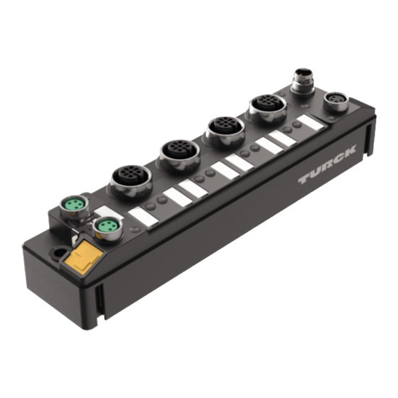
The devices are designed in a fully encapsulated housing with degree of protection IP65/IP67/ IP69K. The TBEN-S2-4IOL IO-Link Master Module has four IO-Link ports for connecting IO-Link devices. In addition to the four IO-Link channels, four universal digital DXP-channels (PNP) are available. -
Page 16: Properties And Features
With the other protocols, the device can only be ac- cessed read-only. Hans Turck GmbH & Co. KG | T +49 208 4952-0 | F +49 208 4952-264 | more@turck.com | www.turck.com... -
Page 17: Io-Link Channels
Protocol Dependent Functions The device Supported the following Ethernet protocol specific functions: PROFINET FSU - Fast Start-Up (prioritized startup) Topology discovery Address assignment via LLDP MRP (Media Redundancy Protocol) EtherNet/IP™ QC – QuickConnect Device Level Ring (DLR) 5.4.2 IO-Link channels The IO-Link master module has four Class A IO-Link channels. -
Page 18: Mounting
Repeat steps 1 to 4 until the module group in complete. Fig. 5: Step 1 Fig. 6: Step 2 Fig. 7: Step 3 Fig. 8: Step 4 Hans Turck GmbH & Co. KG | T +49 208 4952-0 | F +49 208 4952-264 | more@turck.com | www.turck.com... -
Page 19: Combine Tben-S Modules For Single And Composite Mounting On A Din Rail
6.1.2 Combine TBEN-S modules for single and composite mounting on a DIN rail The TBNN-S0-DRS adapter serves for single and composite mounting of TBEN-S modules on a DIN rail. NOTICE Incorrect mounting Missing grounding may cause malfunction „ Align the adapters so that the arrow on the locking lever points in the direction of the M8 Ethernet sockets. -
Page 20: Attach Tben-S Modules To A Mounting Plate
„ To avoid material abrasion and color changes: Protect the device from direct sunlight, e.g. by using protective shields. Hans Turck GmbH & Co. KG | T +49 208 4952-0 | F +49 208 4952-264 | more@turck.com | www.turck.com... -
Page 21: Grounding The Device
6.5.1 Equivalent wiring diagram and shielding concept The equivalent circuit diagrams and shielding concepts of the TBEN-S module variants are shown in the following figures: Fig. 15: TBEN-S2-4IOL– equivalent wiring dia- gram and shielding concept 6.5.2 Fieldbus and I/O level shielding The fieldbus and the I/O level of the TBEN-S modules can be grounded separately. -
Page 22: Grounding The Device - I/O And Fieldbus Level
Use a slim slotted screwdriver in order to lift up and remove the grounding clamp. Fig. 18: Use a flat slotted screwdriver to push the grounding clip forwards and remove it. Hans Turck GmbH & Co. KG | T +49 208 4952-0 | F +49 208 4952-264 | more@turck.com | www.turck.com... -
Page 23: Grounding The Device - Mounting On A Din Rail
Mounting the grounding clip: grounding the fieldbus level directly „ Place the grounding clip between the fieldbus connectors by using a screwdriver in such way that the clip contacts the metal housing of the connectors. The shielding of the fieldbus cables is connected to the grounding clip. Fig. 19: Mounting the grounding clip 6.5.4 Grounding the device –... -
Page 24: Connecting
3 = TX – 4 = TX – 4 = RX – Fig. 21: Ethernet connectors – pin assignment P1 and P2 Hans Turck GmbH & Co. KG | T +49 208 4952-0 | F +49 208 4952-264 | more@turck.com | www.turck.com... -
Page 25: Connecting The Supply Voltage
Connecting the supply voltage For the connection to the power supply, the device has two 4-pin M8 connectors. V1 and V2 are galvanically isolated. NOTICE Interchanging of Ethernet- and power cables Destruction of module electronic „ Observe using the correct M8-connectors when connecting Ethernet- and power cables: - Ethernet: P1 and P2, supply voltage: X1and X2... -
Page 26: Supply Concept
Pin 2 Digital in- or output (DXP) Pin 3 Ground V2 Pin 4 IO-Link or digital input Pin 5 Not connected Hans Turck GmbH & Co. KG | T +49 208 4952-0 | F +49 208 4952-264 | more@turck.com | www.turck.com... -
Page 27: Setting The Ip Address
The device is factory set to IP address 192.168.1.254 and does not have a PROFINET device name. The IP address can be set via the Turck Service Tool, the DTM, the web server, a DHCP server or PROFINET DCP. The following example shows the setting of the IP address via the Turck Service Tool. - Page 28 Change the IP address and if necessary the network mask and gateway. „ Accept the changes by clicking Set in device. Fig. 29: Turck Service Tool – Change device configuration Hans Turck GmbH & Co. KG | T +49 208 4952-0 | F +49 208 4952-264 | more@turck.com | www.turck.com...
-
Page 29: Argee/Flc
ARGEE/FLC The ARGEE FLC programming software can be downloaded free of charge from www.turck.com The Zip archive "SW_ARGEE_Environment_Vx.x.zip" contains the software and the respective software documentation. Commissioning an IO-Link device with IO-Link V1.0 IO-Link devices in accordance with IO-Link specification V1.0 do not support data storage. If an IO-Link V1.0 device is used, data storage at the IO-Link port must be deactivated. -
Page 30: Commissioning An Io-Link Device With Io-Link V1.1
Fig. 31: Example: Reset device to factory settings via DTM „ Connect the IO-Link V1.1 device. The LED IOL at the IO-Link port is green, IO-Link communication active. Hans Turck GmbH & Co. KG | T +49 208 4952-0 | F +49 208 4952-264 | more@turck.com | www.turck.com... - Page 31 Delete the data storage memory via parameters „ Set Data storage mode to deactivated, clear. „ Load the parameter changes into the device. „ Re-activate the data storage, if necessary. „ Load the parameter changes into the device. „ Connect the IO-Link V1.1 device. The LED IOL at the IO-Link port is green, IO-Link communication active.
-
Page 32: Read In Connected Io-Link Devices: Topology Scan In The Dtm
Either the respective sensor DTMs in PACTware or the sensor IODDs via IODD DTM Configurator have to be installed. Fig. 33: PACTware – topology scan Hans Turck GmbH & Co. KG | T +49 208 4952-0 | F +49 208 4952-264 | more@turck.com | www.turck.com... -
Page 33: Commissioning The Device In Profinet
8.6.2 Device model – TBEN-S2-4IOL The TBEN-S2-4IOL provides 4 parameterizable I/O-Link-channels and 4 universal I/O-channels (DXP). In addition to that, 3 virtual channels are provided via GSDML in PROFINET. Those chan- nels are used to map the different diagnostic and status (IO-Link and VAUX diagnostics, IO-Link Events, module status) data into the master's process image . -
Page 34: Address Setting In Profinet
Assignment of a unique plant specific name to the respective field device. Assignment of the IP address from the IO-Controller before the system start-up based on the plant-specific (unique) name. Hans Turck GmbH & Co. KG | T +49 208 4952-0 | F +49 208 4952-264 | more@turck.com | www.turck.com... -
Page 35: Fsu - Fast Start-Up (Prioritized Startup)
PROFINET naming convention The names are assigned via DCP. The device name must meet the requirements of the Domain Name System (DNS) (see below). The device name is checked for correct spelling during input. NOTE The maximum length of the device name is 255 characters according to the specific- ation. - Page 36 45044 0xAFF4 I&M4-functions STRING[54] read/ I&M Signature write 45045… 0xAFF5 I&M5 to I&M15- not supported 45055 … functions 0xAFFF Hans Turck GmbH & Co. KG | T +49 208 4952-0 | F +49 208 4952-264 | more@turck.com | www.turck.com...
- Page 37 Acyclic I/O channel user data Index Name Data type Access Comment Dec. Hex. 0x01 Module paramet- specific read/ Parameters of the module write 0x02 Module type ENUM read Contains the module type UINT8 0x03 Module versio UINT8 read Firmware version of I/O chan- nels 0x04 Module ID...
-
Page 38: The Io-Link Function Block Iol_Call
Fix value (65098): defines the access to be an IO-Link CALL IOL_INDEX Number of the IO-Link index which has to be read IOL_SUBINDEX INT Definition of a possible sub index. Hans Turck GmbH & Co. KG | T +49 208 4952-0 | F +49 208 4952-264 | more@turck.com | www.turck.com... - Page 39 Designation Data Meaning acc. IO-Link type spec. Length of the data to be read/written. This information is not neces- sary for the Siemens IOL_CALL. RECORD_IOL_ Source/destination for the data to be read/written. DATA IOL_CALL – output variables Designation Data Meaning acc.
- Page 40 Error: IOL index < 32767 or > 65535 selected 0x8002 Wrong port address Port address not available 0x8003 Wrong port function Port function not available … reserved Hans Turck GmbH & Co. KG | T +49 208 4952-0 | F +49 208 4952-264 | more@turck.com | www.turck.com...
- Page 41 IOL-Error Type Designation acc. to IO- Meaning Link Spec. 0x1000 COM_ERR Communication error Possible source: the addressed port is parameterized as digital input DI and is not in IO-Link mode 0x1100 I_SERVICE_TIMEOUT Timeout in communication, device does not respond in time 0x5600 M_ISDU_CHECKSUM Master reports checksum error, access to device not...
-
Page 42: Connecting The Device To A Siemens Plc In Profinet
The programming software has been started. A new project has been created. The PLC has been added to the project. Hans Turck GmbH & Co. KG | T +49 208 4952-0 | F +49 208 4952-264 | more@turck.com | www.turck.com... -
Page 43: Installing The Gsdml File
8.7.1 Installing the GSDML file The GSDML file can be downloaded for free from www.turck.com Ò „ Adding the GSDML-file: Click Options Manage general station description files (GSD). Fig. 37: Adding the GSDML-file „ Installing the GSDML-file: Define the source path for the GSDML-file and click Install. -
Page 44: Connecting The Devices To The Plc
„ Connect the devices to the PLC in the Devices & networks editor. Fig. 39: Connecting the device to the PLC Hans Turck GmbH & Co. KG | T +49 208 4952-0 | F +49 208 4952-264 | more@turck.com | www.turck.com... -
Page 45: Assigning The Profinet Device Name
8.7.3 Assigning the PROFINET device name Ò „ Select Online access Online & diagnostics. Ò „ Functions Assign PROFINET device name. „ Assign the desired PROFINET device name with Assign name. Fig. 40: Assigning the PROFINET device name V01.00 | 2019/10... -
Page 46: Setting The Ip Address In Tia Portal
Optional mapping of the IO-Link events into the master's process image. Module status Optional mapping of the module status into the masters process image. Hans Turck GmbH & Co. KG | T +49 208 4952-0 | F +49 208 4952-264 | more@turck.com | www.turck.com... - Page 47 Turck temperature Port configuration generic: sensor, IN 1 WORD TS-530-LI2UPN8X-... Port 2 1 Bit IN Port 3 2 byte IN Turck linearity sensor, Port-configuration specific: Li100P0-Q25LM0-... Li100P0-QU25L Port 4 2 byte IN Turck I/O hub, Port configuration specific: 2 byte OUT...
- Page 48 Ò Ò „ Click Properties General Module parameters. „ Set the device parameters. Fig. 43: TIA-Portal – Parameterizing generic IO-Link devices Hans Turck GmbH & Co. KG | T +49 208 4952-0 | F +49 208 4952-264 | more@turck.com | www.turck.com...
-
Page 49: Going Online With The Plc
8.7.6 Going online with the PLC „ Start the online mode (Go online). The device has been successfully connected to the PLC. Fig. 44: Starting the online mode 8.7.7 PROFINET – mapping The PROFINET mapping corresponds to the data mapping described in the sections "Process In- put Data”... -
Page 50: Use The Io_Link_Device Function Block In Tia Portal
Portal V15, the old IOL_CALL function block can be used to access the port 0 func- tions. Siemens provides the function block for TIA-Portal users underhttps://sup- port.industry.siemens.com. Hans Turck GmbH & Co. KG | T +49 208 4952-0 | F +49 208 4952-264 | more@turck.com | www.turck.com... - Page 51 HW identifier of the basic slot (slot 1), for example with CPU 1511-PN (used in this example) Start address of the input data of the IO-Link master e.g. with CPU 315 Fig. 46: Hardware identifier: Basic slot of the TBEN-S2-4IOL in the example V01.00 | 2019/10...
- Page 52 The I/O hub TBIL-M1-16DXP is connected to port 4. IOL_INDEX 0x12 Index for product name Fig. 47: IO_LINK_DEVICE – input variables for read access Hans Turck GmbH & Co. KG | T +49 208 4952-0 | F +49 208 4952-264 | more@turck.com | www.turck.com...
- Page 53 „ Activate the read access via a rising edge at REQ. Fig. 48: IO_LINK_DEVICE – activate read access In this example, the result of this request can be seen in the watch table (row 19 and fol- lowing) in the IO-Link Record. Fig. 49: IO_LINK_DEVICE –...
- Page 54 0x05 = 600 ms measured value update time, display rotated by 180°. Fig. 50: Extract from the documentation for TS-500-… Hans Turck GmbH & Co. KG | T +49 208 4952-0 | F +49 208 4952-264 | more@turck.com | www.turck.com...
- Page 55 „ Write the input variables of the function block via control variable as follows: „ Activate the write access in the function block via RD_WR Sensor 1= TRUE. Variable True Meaning TRUE Send a write request Hardware identifier of the Basic slot according to the configuration in the Device view Function block instance Length of the data to be written [byte]...
- Page 56 Fig. 53: IO_LINK_DEVICE – activate read access The display is now rotated about 180° and set to an actualization time of 600 ms Hans Turck GmbH & Co. KG | T +49 208 4952-0 | F +49 208 4952-264 | more@turck.com | www.turck.com...
-
Page 57: Commissioning The Device In Modbus Tcp
Commissioning the device in Modbus TCP 8.8.1 Implemented Modbus functions The devices support the following functions for accessing process data, parameters, dia- gnostics and other services. Function codes Read Coils – reading multiple output bits Read Discrete Inputs – reading multiple input bits Read Holding Registers –... - Page 58 0x9000, 0x9001 36864, 36865 436865, 436866 Diagnostics 0xA000, 0xA001 40960, 40961 440961, 440962 Parameters 0xB000, 0xB001 45056, 45057 445057, 445058 Hans Turck GmbH & Co. KG | T +49 208 4952-0 | F +49 208 4952-264 | more@turck.com | www.turck.com...
- Page 59 Register 0x1130: Modbus connection mode This register defines the behavior of the Modbus connections. Designation Value Meaning MB_OnlyOneWritePermission All Modbus connections receive the write au- thorization Only one Modbus connection can receive the write permission. A write permission is opened until a Disconnect.
-
Page 60: Data Width
FC16 and FC23. The parameters are saved. 8.8.3 Data width Module Process input Process output Alignment TBEN-S2-4IOL 208 byte word by word Hans Turck GmbH & Co. KG | T +49 208 4952-0 | F +49 208 4952-264 | more@turck.com | www.turck.com... -
Page 61: Register Mapping
8.8.4 Register mapping Register no. Bit no. 15 14 13 12 11 10 9 Input data 0x0000… Process input data 0x00xx [} 116] Module status 0x00xx see status- and control word + 1 register Output data 0x0800… Process output data 0x08xx [} 118] Diagnostics 0xA000... -
Page 62: Error Behavior (Watchdog)
"0" after the watchdog time has expired, unless another protocol (PROFINET, Eth- erNet/IP™) has been activated in the meantime. Hans Turck GmbH & Co. KG | T +49 208 4952-0 | F +49 208 4952-264 | more@turck.com | www.turck.com... -
Page 63: Commissioning The Device In Ethernet/Ip
104, 150, 151, 152 Configuration assembly Instance 8.9.2 EDS files and catalog files The EDS and catalog files can be downloaded free of charge from www.turck.com. TBEN-S_ETHERNETIP.zip 8.9.3 Device Level Ring (DLR) The devices support DLR. The Device Level Ring (DLR)-redundancy protocol is used to increase the stability of EtherNet/IP™... - Page 64 (the last 3 bytes of the MAC-ID). 0x07 Product STRUCT OF: i.e.: TBEN-S2-4IOL name USINT STRING [13] Hans Turck GmbH & Co. KG | T +49 208 4952-0 | F +49 208 4952-264 | more@turck.com | www.turck.com...
- Page 65 Device status Name Definition 0…1 reserved default = 0 Configured TRUE = 1: The application in the device has been con- figured (default setting). reserved default = 0 4…7 Extended Device status 0011 = no I/O connection established 0110 = at least one I/O connection in RUN mode 0111 = at least one I/O connection established, all in IDLE mode...
- Page 66 Dec. Hex. 0x01 Get_Attribute_All Returns a predefined list of object attributes. 0x0E Get_Attribute_Single Returns the content of a specified attribute. Hans Turck GmbH & Co. KG | T +49 208 4952-0 | F +49 208 4952-264 | more@turck.com | www.turck.com...
- Page 67 Assembly instances EtherNet/IP™ Input assembly Output assembly Configuration assembly Supported by Connection Instance Size Instance Size Instance Size Rockwell Omron [8 bit] [8 bit] [8 bit] Exclusive Owner 103 Exclusive Owner (Omron) IOL 4 IN/4 OUT, diagnostics IOL 6 IN/6 OUT, diagnostics IOL 8 IN/8 OUT, diagnostics...
- Page 68 Device ID 0x21 34…49 0x22… IO-Link port 2 0x31 50…65 0x32… IO-Link port 3 0x41 66…81 0x42… IO-Link port 4 0x51 Hans Turck GmbH & Co. KG | T +49 208 4952-0 | F +49 208 4952-264 | more@turck.com | www.turck.com...
- Page 69 Device configuration data Parameter name Value Meaning LED-behavior (PWR) at PWR-LED constant red at V2 undervoltage. V2 undervoltage green PWR-LED is blinking green at V2 under- voltage. ETH x Port Setup Auto negotiation The port is set to autonegotiation. 100BT/FD Fix setting of the communication paramet- ers for the Ethernet port to: 100BaseT...
- Page 70 0x66 Port 16th Event) Qualifier (16th Event) 0x67 Event Code low byte (16th Event) Event Code high byte (16th Event) Hans Turck GmbH & Co. KG | T +49 208 4952-0 | F +49 208 4952-264 | more@turck.com | www.turck.com...
- Page 71 Instance 120 – 4 bytes IN/4 bytes OUT, diagnostics The description of the parameters can be found in chapter “Parameterizing and configur- ing” [} 116] Word no. Bit no. Status word [} 120] 0x00 FCE - DIAG Inputs 0x01 DXP7 DI6 DXP5 DI4 DXP3 DI2 DXP1 DI0 (SIO)
- Page 72 DVS2 - DVS0 IO-Link – process input data 0x03… 2 words per port 0x04 0x05… 0x06 0x07… 0x08 0x09… 0x0A Hans Turck GmbH & Co. KG | T +49 208 4952-0 | F +49 208 4952-264 | more@turck.com | www.turck.com...
- Page 73 Instance 122 – 6 bytes IN/6 bytes OUT, diagnostics The description of the parameters can be found in chapter “Parameterizing and configur- ing” [} 116] Word no. Bit no. Status word [} 120] 0x00 FCE - Diag Inputs 0x01 DXP7 DI6 DXP5 DI4 DXP3 DI2 DXP1 DI0 (SIO)
- Page 74 DVS2 - DVS0 IO-Link – process input data 0x03… 3 words per port 0x05 0x06… 0x08 0x09… 0x0B 0x0C… 0x0E Hans Turck GmbH & Co. KG | T +49 208 4952-0 | F +49 208 4952-264 | more@turck.com | www.turck.com...
- Page 75 Instance 124 – 8 bytes IN/8 bytes OUT, diagnostics The description of the parameters can be found in chapter “Parameterizing and configur- ing” [} 116] Word no. Bit no. Status word [} 120] 0x00 Diag Inputs 0x01 DXP7 DI6 DXP5 DI4 DXP3 DI2 DXP1 DI0 (SIO) (SIO)
- Page 76 DVS2 - DVS0 IO-Link – process input data 0x03… 4 words per port 0x06 0x07… 0x0A 0x0B… 0x0E 0x0F… 0x12 Hans Turck GmbH & Co. KG | T +49 208 4952-0 | F +49 208 4952-264 | more@turck.com | www.turck.com...
- Page 77 Output assembly instances EtherNet/IP™ Output assembly Control word DXP outputs IO-Link out- VAUX [byte] Connection [byte] [byte] puts [byte] Instance Size [8 bit] Exclusive Owner 104 IOL 4 IN/4 OUT IOL 6 IN/6 OUT IOL 8 IN/8 OUT Instance 104 – Exclusive Owner The description of the parameters can be found in chapter “Parameterizing and configur- ing”...
- Page 78 DXP7 DXP5 DXP3 DXP1 IO-Link process output data 0x02… 4 words per port 0x05 0x06… 0x09 0x0A… 0x0D 0x0E… 0x11 Hans Turck GmbH & Co. KG | T +49 208 4952-0 | F +49 208 4952-264 | more@turck.com | www.turck.com...
- Page 79 This object is used for connection and connectionless communications, including establishing connections across multiple subnets. The following description of the Ethernet Link Object is taken from the CIP specification, Vol. 2, Rev. 2.1 by ODVA & ControlNet International Ltd. and adapted to the Turck products. Common services Service code...
- Page 80 0x06 Host name STRING 0 = no Host Name con- figured 0x0C QuickConnect BOOL 0 = deactivate 1 = activate Hans Turck GmbH & Co. KG | T +49 208 4952-0 | F +49 208 4952-264 | more@turck.com | www.turck.com...
- Page 81 Common services Service code Class Instance Meaning Dec. Hex. 0x01 Get_Attribute_All 0x02 Set_Attribute_All 0x0E Get_Attribute_Single 0x10 Set_Attribute_Single Interface status The Status attribute indicates the status of the TCP/IP network interface. Refer to the TCP/IP Ob- ject State diagram for a description of object states as they relate to the Status attribute. Designation Meaning 0…3...
- Page 82 The mechanism allows the DHCP client to transmit its host name to the DHCP server. The DHCP server then updates the DNS records on behalf of the client. Hans Turck GmbH & Co. KG | T +49 208 4952-0 | F +49 208 4952-264 | more@turck.com | www.turck.com...
- Page 83 Ethernet Link Object (0xF6) The following description of the Ethernet Link Object is taken from the CIP specification, Vol. 2, Rev. 1.1 by ODVA & ControlNet International Ltd. and adapted to the Turck products. Class attributes Attr.-no. Designation Get/Set Type Value Dec.
- Page 84 1 = local hardware error detected Common services Service code Class Instance Meaning Dec. Hex. 0x01 Get_Attribute_All 0x0E Get_Attribute_Single 0x4C Enetlink_Get_and_Clear Hans Turck GmbH & Co. KG | T +49 208 4952-0 | F +49 208 4952-264 | more@turck.com | www.turck.com...
-
Page 85: Vsc-Vendor Specific Classes
8.9.6 VSC-Vendor Specific Classes In addition to supporting the above named CIP Standard Classes, the device support the vendor specific classes (VSCs) described in the following. Class Code Name Description dec. Hex. 0x64 Gateway Class [} 86] Data and parameters for the field bus specific part of the device. - Page 86 (cannot be deactivated via the EtherNet/IP™ interface). Bit 1: Deactivates Modbus TCP Bit 2: Deactivates PROFINET Bit 15: Deactivates the web server Hans Turck GmbH & Co. KG | T +49 208 4952-0 | F +49 208 4952-264 | more@turck.com | www.turck.com...
- Page 87 UINT 0x06 Max. class attribute UINT One attribute per IO-Link port, 1 attribute (128) for port 0 func- tions) Example: TBEN-L…-8IOL: 1…8, 128 TBEN-S2-4IOL 1…4, 128 Instance attributes Common services Service code Class Instance Service name Dec. Hex. 0x0E Get_Attribute_Single Returns the content of a specified attribute.
- Page 88 (e.g. Turck I/O hub TBIL-M1-16DXP) ac- cording to IODD Data byte 1 0x00 UINT Data byte 2 0x00 USINT The index has no sub index. Hans Turck GmbH & Co. KG | T +49 208 4952-0 | F +49 208 4952-264 | more@turck.com | www.turck.com...
- Page 89 CIP Service Response: Name Data type Description ISDU data Array of Byte Error-free access: Content: 54 42 49 4C 2D 4D 31 2D 31 36 44 58 50 (TBIL- M1-16DXP) Access error: Content: Error code Write_ISDU – Request Data Value/content Description Class 0x67...
- Page 90 Device can not respond to master request 0x8000 APP_DEV Application error in the device 0x8011 IDX_NOTAVAIL Index not available 0x8012 SUBIDX_NOTAVAIL Sub-Index not available Hans Turck GmbH & Co. KG | T +49 208 4952-0 | F +49 208 4952-264 | more@turck.com | www.turck.com...
- Page 91 Error code Designation acc. to specification Meaning 0x8020 SERV_NOTAVAIL The service is temporarily not available. 0x8021 SERV_NOTAVAIL_LOCCTRL Service temporarily not available, device is busy (e. g. teaching or parameterization of the device at the device active) 0x822 SERV_NOTAVAIL_DEVCTRL Service temporarily not available, device is busy (e.
- Page 92 DXP 3 – Output value USINT 0x1B DXP 5 – Output value USINT 0x1C DXP 7 – Output value USINT Hans Turck GmbH & Co. KG | T +49 208 4952-0 | F +49 208 4952-264 | more@turck.com | www.turck.com...
- Page 93 IO-Link Port Class (VSC 137) This class provides one instance per IO-Link port at the IO-Link master module. Attr. no. Designation Get/Set Type Meaning Dec. Hex. Parameters 0x01 Operation mode USINT 0 = IO-Link without validation 1 = IO-Link with family compatible device 2 = IO-Link with compatible device 3 = IO-Link with identical device 4 = DI (with parameter access)
- Page 94 Input data word 15 USINT 0x2C Output data word 0 USINT … … … USINT 0x3B Output data word 15 USINT Hans Turck GmbH & Co. KG | T +49 208 4952-0 | F +49 208 4952-264 | more@turck.com | www.turck.com...
- Page 95 IO-Link Events Class (VSC 138) Attr. no. Designation Get/Set Type Meaning Dec. Hex. 0x01 IOL-Event 1 – USINT Port no. of the port which sends the 1st port IO-Link Event. … … 0x10 IOL-Event 16 – USINT Port no. of the port which sends the 16th port IO-Link Event.
-
Page 96: Connecting The Devices To A Rockwell Plc With Ethernet/Ip
A new project has been created in a second instance of RSLogix. The PLC and the Scanner mentioned above have been added to the project in the second in- stance. Hans Turck GmbH & Co. KG | T +49 208 4952-0 | F +49 208 4952-264 | more@turck.com | www.turck.com... -
Page 97: Adding The Devices From The Catalog Files To The New Project
8.10.1 Adding the devices from the catalog files to the new project „ Right-click the device entry and use Copy. Fig. 55: RSLogix – Copying the device entry from catalog file V01.00 | 2019/10... - Page 98 Paste. In this example, the configuration with 4 byte in- and 4 byte output data plus diagnostics TBEN_S2_4IOL_4in4out_diag is used. Fig. 56: RSLogix – predefined configurations of TBEN-S2-4IOL in new project Hans Turck GmbH & Co. KG | T +49 208 4952-0 | F +49 208 4952-264 | more@turck.com | www.turck.com...
-
Page 99: Configuring The Device In Rs Logix
8.10.2 Configuring the device in RS Logix „ Open the device entry by double-clicking. „ Assign a module name. „ Set the IP address of the device. Fig. 57: Setting module name and IP address „ Optional: Set the connection parameters. Fig. 58: Setting the connection parameters V01.00 | 2019/10... -
Page 100: Parameterizing The Device
Open the Controller Tags of the device. „ Parameterize the device via the Controller Tags TBEN_S2_4IOL_4in4out_diag:C. Fig. 59: Parameterizing the Device Hans Turck GmbH & Co. KG | T +49 208 4952-0 | F +49 208 4952-264 | more@turck.com | www.turck.com... -
Page 101: Going Online With The Plc
8.10.4 Going online with the PLC „ Search the network via the Who Active function. „ Select the PLC. „ Set the communication path via Set Project Path. The communication path is set. Fig. 60: Setting the communication path V01.00 | 2019/10... - Page 102 Click Download In the following dialog (Connect To Go Online) „ Confirm all following messages. The project is loaded down to the controller. The connection is established. Hans Turck GmbH & Co. KG | T +49 208 4952-0 | F +49 208 4952-264 | more@turck.com | www.turck.com...
-
Page 103: Reading Process Data
8.10.5 Reading process data „ Open the Controller Tags in the project tree by double-clicking the entry. The access to parameter data (TBEN_S2_4IOL_…:C), input data (TBEN_S2_4IOL_…:I) and output data (TBEN_S2_4IOL_…:O) is possible. Fig. 62: Controller Tags in the project tree V01.00 | 2019/10... -
Page 104: Parameters_Tben_S2-4Iol
0x00 Yes The output at pin 2 is deactivated. Chx (DXPx_ENDO) 0x01 No The output at pin 2 is activated. Hans Turck GmbH & Co. KG | T +49 208 4952-0 | F +49 208 4952-264 | more@turck.com | www.turck.com... - Page 105 Parameter name Value Meaning Description dec. Hex. Operation mode 0x00 IO-Link without validation Pin 4 is operated in IO-Link mode. The master does not check if the connected device matches the configured one. 0x01 IO-Link with compatible Pin 4 is operated in IO-Link mode. device The master checks if the Vendor ID and the MSB of the Device ID (this byte defines the product family)
- Page 106 Influences the sending of IO-Link Events from the master to the fieldbus. Depending on the diagnostics parameterization, the master transmits Events based on their priority to the fieldbus or not. Hans Turck GmbH & Co. KG | T +49 208 4952-0 | F +49 208 4952-264 | more@turck.com | www.turck.com...
- Page 107 Parameter name Value Meaning Description dec. Hex. 0x00 No The master transmits all IO-Link Events to the field- bus. 0x01 Notifications The master transmits all IO-Link Events to the field- bus except for IO-Link notifications. 0x02 Notifications and warnings The master transmits all IO-Link Events to the field- bus except for IO-Link notifications and warnings.
- Page 108 0x54 29.6 0x7A 57.6 0x90 0xA3 118.4 0xB6 15.2 1x56 30.4 0x7C 59.2 0x91 89.6 0xA4 0xB7 auto., 0xFF comp. Hans Turck GmbH & Co. KG | T +49 208 4952-0 | F +49 208 4952-264 | more@turck.com | www.turck.com...
-
Page 109: Adapting Process Data Mapping
9.1.1 Adapting process data mapping The mapping of process data can be adapted application-specifically via the IO-Link master's parameterization. Depending on the used fieldbus, it can be necessary to swap process data word-wise, double word-wise or completely in order to align them to the data structure in the PLC. The process data mapping is determined channel by channel through the parameters process input data mapping and process output data mapping. -
Page 110: Profinet Parameters
Explicit deactivation of the Ethernet ANT Force Mode Deac- protocols or web server tivate Force Mode Deactivate EtherNet/IP™ Deactivate Modbus Deactivate WEB server 0 Hans Turck GmbH & Co. KG | T +49 208 4952-0 | F +49 208 4952-264 | more@turck.com | www.turck.com... -
Page 111: Io-Link Functions For Acyclic Communication
IO-Link functions for acyclic communication The acyclic access to the data of IO-Link devices is realized via IO-Link CALLs. A distinction must be made between data of the IO-Link master (IOLM) and data of connected IO-Link devices (IOLD). The addressing of the IO-Link CALL defines which device is addressed via the CALL: The addressing is defined by the so called Entitiy_Port: Entity_Port 0 = IO-Link master module (IOLM) Entity_Port 1 = IO-Link device at IO-Link port 1... - Page 112 High or- low byte of the error code sent Event Code low byte … … Qualifier see byte 2…5 Port Event Code high byte Event Code low byte Hans Turck GmbH & Co. KG | T +49 208 4952-0 | F +49 208 4952-264 | more@turck.com | www.turck.com...
- Page 113 Subindex 66: Set Default Parameterization Writing this object sets the IO-Link master back to factory settings. Any parameter setting and configuration is overwritten. The data storage buffer is deleted as well. Entity_Port IO-Link sub index Read/write Length Write 4 byte Structure of the reset command: Byte 3 Byte 2...
- Page 114 Diagnostic bit Meaning NO_DS The parameterized port mode does not support data storage. Remedy: Change the parameterization of the port. Hans Turck GmbH & Co. KG | T +49 208 4952-0 | F +49 208 4952-264 | more@turck.com | www.turck.com...
- Page 115 Diagnostic bit Meaning DS_F Error in the data storage, synchronization not possible Possible causes: Connected device does not support data storage Overflow of the data storage buffer Remedy: „ Connect a device that supports data storage. „ Clear the data storage buffer. „...
-
Page 116: Operating
Event Code low byte (16th Event) Event Code high byte (16th Event) Module status (status word) 0x67 COM V1 DIAG Hans Turck GmbH & Co. KG | T +49 208 4952-0 | F +49 208 4952-264 | more@turck.com | www.turck.com... - Page 117 Meaning of process data bits Name Value Meaning I/O data Digital input x No signal at DI (pin 4, SIO) Signal at DI (pin 4, SIO) DXPx configurable digital channel (DXP channel) No input signal at DXP-channel (pin 2) Input signal at DXP-channel (pin 2) DVSx Input value valid (Data Valid Signal) The IO-Link data are invalid.
-
Page 118: Process Output Data
(0…32 byte per channel) 0x40 Name Value Meaning I/O data DXPx DXP output Output inactive Output active, max. output current 2 A Hans Turck GmbH & Co. KG | T +49 208 4952-0 | F +49 208 4952-264 | more@turck.com | www.turck.com... -
Page 119: Led Displays
10.3 LED displays The device has the following LED indicators: Power supply Group and bus errors Status Diagnostics LED PWR Meaning No voltage connected or under voltage at V1 Green Voltage V1 and V2 OK No voltage connected or under voltage at V2 LED BUS Meaning No voltage connected... -
Page 120: Software Diagnostic Messages
Activating or deactivating the status and control word modifies the process data mapping. Control word The control word has no function. Hans Turck GmbH & Co. KG | T +49 208 4952-0 | F +49 208 4952-264 | more@turck.com | www.turck.com... -
Page 121: Diagnostic Telegram
10.4.2 Diagnostic telegram Channel Byte no. Bit 7 Bit 6 Bit 5 Bit 4 Bit 3 Bit 2 Bit 1 Bit 0 DXP diagnostics ERR DXP7 - ERR DXP5 - ERR DXP3 - ERR DXP1 - IO-Link Device diagnostic messages Master diagnostics IO-Link EVT1... - Page 122 A temperature diagnosis is available on the connected device. PRMERR Parameterization error The connected device reports a parameterization error (loss of parameters, no parameter initialization, etc.). Hans Turck GmbH & Co. KG | T +49 208 4952-0 | F +49 208 4952-264 | more@turck.com | www.turck.com...
-
Page 123: Profinet Diagnostics
Meaning ULVE Upper limit value exceeded The process value exceeds the parameterized measurement range or the chosen measurement range has been chosen too low. VLOW Undervoltage One of the voltages at the connected device is below the defined range. VLOW Overvoltage One of the voltages at the connected device is below the defined range. -
Page 124: Using The Data Storage Mode
The data set in the device is always the reference data set. The synchronization of the parameter sets is unidirectional towards to the master. The status of the DS_UPLOAD_FLAG is ignored. Hans Turck GmbH & Co. KG | T +49 208 4952-0 | F +49 208 4952-264 | more@turck.com | www.turck.com... -
Page 125: Parameter "Data Storage Mode" = Overwrite
IOLM IOLD Fig. 64: Data storage mode = read in – parameter set in the device changed 10.5.2 Parameter ”data storage mode” = overwrite The data set in the master is always the reference data set. The synchronization of the parameter sets is unidirectional towards to the device. The status of the DS_UPLOAD_FLAG is ignored. -
Page 126: Troubleshooting
IO-Link port with the diagnosis if the process value parameter Process input data in- Ò cannot be measured. valid No diagnostic generated. Hans Turck GmbH & Co. KG | T +49 208 4952-0 | F +49 208 4952-264 | more@turck.com | www.turck.com... -
Page 127: Maintenance
The firmware of the device can be updated via FDT/DTM. The PACTware™ FDT frame applica- tion, the DTM for the device and the current firmware are available as downloads free of charge from www.turck.com. NOTICE Interruption of the power supply during the firmware update Risk of device damage due to faulty firmware update „... - Page 128 Fig. 68: Selecting the Ethernet interface „ Double-click the connected device. PACTware™ opens the bus address management. Fig. 69: Opening the busaddress management Hans Turck GmbH & Co. KG | T +49 208 4952-0 | F +49 208 4952-264 | more@turck.com | www.turck.com...
- Page 129 „ Search for connected Ethernet devices: Click the Search icon. „ Select the required device. Fig. 70: Selecting the device „ Click Firmware Download to start the firmware update. Fig. 71: Starting the firmware update „ Select the storage location and confirm with OK. PACTware™...
-
Page 130: Repair
Disposal The devices must be disposed of correctly and must not be included in normal household garbage. Hans Turck GmbH & Co. KG | T +49 208 4952-0 | F +49 208 4952-264 | more@turck.com | www.turck.com... -
Page 131: Technical Data
Technical Data Technical Data Power supply Supply voltage 24 VDC Permissible range 18…30 VDC IO-Link 20.4…28.8 VDC Total current max. 4 A per voltage group Operating current V1: min. 50 mA, max. 110 mA V2: min.10 mA, max. 115 mA Sensor/actuator supply VAUX2 Supply from V2, not short-circuit proof, max. - Page 132 Max. 32 byte input/32 byte output Input data max. 32 Byte per channel Output data max. 32 Byte per channel Hans Turck GmbH & Co. KG | T +49 208 4952-0 | F +49 208 4952-264 | more@turck.com | www.turck.com...
- Page 133 Technical Data Transmission rate 4,8 kbps (COM 1) 38,4 kbps (COM 2) 230,4 kbps (COM 3) Transmission cable Length: max. 20 m standard lines, 3- or 4-wire (depending on the application), unshiel- Mounting Type of mounting 2 mounting holes, Ø 4,6 mm Standard/Directive conformity Vibration test According to EN 60068-2-6...
- Page 134 Over 30 subsidiaries and over 60 representations worldwide! D301369 | 2019/10 D301369 www.turck.com...
Need help?
Do you have a question about the TBEN-S2-4IOL and is the answer not in the manual?
Questions and answers