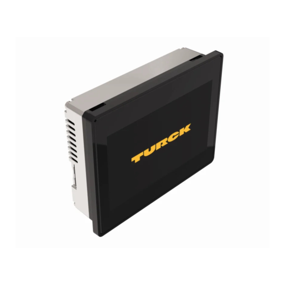
turck TX700 HMI/PLC Series Operating Instructions Manual

turck TX700 HMI/PLC Series Operating Instructions Manual

Hide thumbs Also See for TX700 HMI/PLC Series:

Advertisement

Your Global Automation Partner
TX700
HMI/PLC Series
Operating instructions

Advertisement

Table of Contents
loading
Need help?

Need help?

Do you have a question about the TX700 HMI/PLC Series and is the answer not in the manual?

Questions and answers

Summary of Contents for turck TX700 HMI/PLC Series

  • Page 1 Your Global Automation Partner TX700 HMI/PLC Series Operating instructions...
  • Page 2 Hans Turck GmbH & Co. KG | T +49 208 4952-0 | F +49 208 4952-264 | more@turck.com | www.turck.com...
  • Page 3: Table Of Contents

    Table of Contents About this Document Target Groups Explanation of Symbols Used Other Documents Feedback about these Instructions Product Overview Product Identification Type Code List of Available Devices Standards and Approvals Special Instruction for Use Technical Specifications Technical Data Environmental Conditions/Protection Class Electromagnetic Compatibility (EMC) Dimensions 4.4.1...
  • Page 4 Unpacking and Packing the Device 13.1 TX705/TX707/TX710 13.2 TX715/TX721 Appendix: Accessories 14.1 Plug-in Extension Modules 14.2 Mounting Material/Power Supply Connector 14.3 USB/SD Accessory Hans Turck GmbH & Co. KG | T +49 208 4952-0 | F +49 208 4952-264 | more@turck.com | www.turck.com...
  • Page 5: About This Document

    This symbol denotes actions that the user must carry out. ➤ ➤ RESULTS OF ACTION This symbol denotes relevant results of actions. ➥ ➤ Other Documents The following additional documents are available online at www.turck.com ■ Data sheet ■ Installation guide ■ CAD data 2018/09...
  • Page 6: Feedback About These Instructions

    Operator interface with TFT color 15.6” widescreen display multitouch projected capacitive touchscreen ■ TX721 Operator interface with TFT color 21.5” widescreen display multitouch projected capacitive touchscreen Hans Turck GmbH & Co. KG | T +49 208 4952-0 | F +49 208 4952-264 | more@turck.com | www.turck.com...
  • Page 7: Type Code

    Serial number number V… Internal version ID of the product Type Code TX 7 05 – P3 CV 01 Produktfamilie Serie Bildschirmdiagonale Produktfamilie Serie Größe Turck HMI/PLC TX700 Serie 5" 7" 10,1" 15,6" 21,5" Visualisierung Kommunikation Visualisierung Kommunikation 00 ohne SPS Funktionalität XX ohne Visualisierungsfunktionalität...
  • Page 8: Standards And Approvals

    Care shall be taken not to allow layers of dust to form on the graphic panel in a way that might cause the accumulation of static charges. Hans Turck GmbH & Co. KG | T +49 208 4952-0 | F +49 208 4952-264 | more@turck.com | www.turck.com...
  • Page 9: Technical Specifications

    Technical Specifications Technical Data TX705 TX707 TX710 TX715 TX721 Touchscreen True Glass Projected Capacitive, Multitouch technology Display/backlight TFT Color / LED Colors 64 K Brightness 300 Cd/m² typ. 500 Cd/m² typ. 500 Cd/m² typ. 400 Cd/m² typ. 300 Cd/m² typ. Resolution 800x480 800 ×...
  • Page 10: Environmental Conditions/Protection Class

    (Time of continuos operation until the brightness of the backlight reaches 50 % of the rated value when the surrounding air tempera- ture is 25 °C). Hans Turck GmbH & Co. KG | T +49 208 4952-0 | F +49 208 4952-264 | more@turck.com | www.turck.com...
  • Page 11: Dimensions

    NOTE Extended use in environments where the surrounding air temperature is 40 °C or higher may degrade backlight quality/reliability/durability. Dimensions 4.4.1 TX705 Fig.2: Dimensions TX705 Model TX705 147 mm/5.78” 107 mm/4.21” 136 mm/5.35” 96 mm/3.78” 56 mm/2.40” 8 mm/0.31” 2018/09...
  • Page 12: Tx707/Tx710/Tx715/Tx721

    411 mm/16.18” 256 mm/10.00” 56 mm/2.20” 8 mm/0.31” TX721 552 mm/21.73” 347 mm/13.66” 541 mm/21.30” 336 mm/13.22” 56 mm/2.20” 8 mm/0.31” Hans Turck GmbH & Co. KG | T +49 208 4952-0 | F +49 208 4952-264 | more@turck.com | www.turck.com...
  • Page 13: Installing The Hmi

    Installing the HMI Installation Environment Avoid prolonged exposition to direct sunlight to avoid the risk of overheating the device. The equipment is not intended for installation in contact with corrosive chemical compounds. Check the resistance of the front panel film to a specific compound before installation. Do not use tools of any kind (screwdrivers, etc.) to operate the touch screen of the panel.
  • Page 14: Connecting

    Serial Port Ethernet port 0 (10/100 Mbit) Ethernet port 1 (10/100 Mbit) Expansion slot for plug-in modules SD card slot Hans Turck GmbH & Co. KG | T +49 208 4952-0 | F +49 208 4952-264 | more@turck.com | www.turck.com...
  • Page 15: Tx707/Tx710/Tx715/Tx721

    TX707/TX710/TX715/TX721 Fig.7: TX707/TX710/TX715/TX721 – connection options Connector Description USB Port Ethernet port 2 (10/100 Mbit) Ethernet port 1 (10/100 Mbit) Serial port Ethernet port 0 (10/100/1000 Mbit) Power supply 2 × Expansion slot for plug-in modules SD card slot 2018/09...
  • Page 16: Serial Port

    The communication cable must be chosen for the type of device being connected. Ethernet Ports The Ethernet ports have two status indicators. . Fig.9: Ethernet ports Hans Turck GmbH & Co. KG | T +49 208 4952-0 | F +49 208 4952-264 | more@turck.com | www.turck.com...
  • Page 17: Sd Card Slot

    SD Card Slot Specification Supported types SD, SDHC Format FAT, FAT32 Max. size Limited by the FAT32 specification ≤ 4 GB for one single file ≤ 32 GB in total USB Port Allowed formatting Format FAT, FAT32 Max. size Limited by the FAT32 specification ≤...
  • Page 18: Slot Assignment - Can-Port

    Slot 2 Mode COM2 COM Port 2 Slot 3 Mode COM3 COM Port 3 Slot 4 Mode COM3 COM Port 3 Hans Turck GmbH & Co. KG | T +49 208 4952-0 | F +49 208 4952-264 | more@turck.com | www.turck.com...
  • Page 19: Optional Plug-In Module Installation Procedure

    Slot 1 to Slot 4 refer to the Extension Slots on the rear of the device, see „Abb. 10: Erweiterungss- teckplätze für Plug-in-Module“ S. 17. Optional Plug-in Module Installation Procedure TX-CAN/ TX-IO-DX06 TX-IO-XX03 Fig.11: Installation of optional plug-in modules 2018/09...
  • Page 20: Connecting The Power Supply

    1 MΩ resistor in parallel with a 4,7 nF capacitor. The power supply must have double or reinforced insulation. The suggested wiring for the power supply is shown below. Hans Turck GmbH & Co. KG | T +49 208 4952-0 | F +49 208 4952-264 | more@turck.com | www.turck.com...
  • Page 21: Battery

    Fig.13: Power supply wiring All the electronic devices in the control system must be properly grounded. Grounding must be performed according to applicable regulations. NOTE The power connector is part of the scope of delivery and can be ordered as spare part, see „14 Anhang: Zubehör“...
  • Page 22: Tx705

    Battery TX705 Fig.14: Battery position TX705 TX707/TX710/TX715/TX721 Fig.15: TX707/TX710/TX715/TX721 Hans Turck GmbH & Co. KG | T +49 208 4952-0 | F +49 208 4952-264 | more@turck.com | www.turck.com...
  • Page 23: Special Instruction For Use

    CODESYS (≥ V 3.5.12.0) and the package “TXxxx HMI/PLC series” for the HMI/PLCs have to be installed on a PC computer running Microsoft Windows. The CODESYS software as well as the CODESYS package for the HMI/PLCs can be downloaded from www.turck.com. 11.2 Programming with TX VisuPro For programming the HMI/PLCs with TX VisuPro, the software tool has to be installed on a PC computer running Microsoft Windows.
  • Page 24: Adapting The System Settings

    Do not modify the system/network settings during operation. ➤ ➤ Always stop the machine and disconnect the HMI when modifying the system ➤ ➤ settings. Hans Turck GmbH & Co. KG | T +49 208 4952-0 | F +49 208 4952-264 | more@turck.com | www.turck.com...
  • Page 25: Access The System Settings In System Mode

    Status Description Factory default Press “System Setting” button on the HMI screen status TX VisuPro run- Recall context menu and select “System Settings”. To recall the context menu click time running and hold any unused area of the touchscreen for a few seconds. Default hold time is 2 seconds.
  • Page 26: Unpacking And Packing The Device

    To repack the unit, please follow the instructions backwards. 13.2 TX715/TX721 Fig.18: Unpacking TX715/TX721 To repack the unit, please follow the instructions backwards. Hans Turck GmbH & Co. KG | T +49 208 4952-0 | F +49 208 4952-264 | more@turck.com | www.turck.com...
  • Page 27: Appendix: Accessories

    USB 2.0 EXTENSION USB 2.0 extension cable, male (A) to female (A), with active ACTIVE 5M repeater, 5 meters NOTE Further accessories like field bus nodes, bus and supply cables, junction boxes, power supplies etc. can be found on www.turck.com. 2018/09...
  • Page 28 Hans Turck GmbH & Co. KG | T +49 208 4952-0 | F +49 208 4952-264 | more@turck.com | www.turck.com...
  • Page 29 30 subsidiaries and over 60 representations worldwide! 100002669 | 2018/09 *100002669* www.turck.com...

Table of Contents