Table of Contents
Advertisement
Quick Links
Advertisement
Table of Contents

Related Manuals for Massoth 8176001


Summary of Contents for Massoth 8176001
- Page 1 Decoder-Serviceboard 8176001...
-
Page 2: Table Of Contents
Inhaltsverzeichnis Table of Contents Information & Hinweise ....Information ........Lieferumfang ........Description ........Beschreibung (Funktionsumfang) ..Scope of Supply ........ Wichtige Hinweise ......Important Notes ........ Anschlussmöglichkeiten ....Connections ........Decoder-Schnittstellen ...... Decoder Interfaces ......Erweiterte Anschlüsse ....... Extended Connections ....... Eingänge + Ausgänge ...... -
Page 3: Information
WICHTIG: Bitte lesen Sie diese IMPORTANT: Please read this Bedienungsanleitung vor Inbetrieb- manual thoroughly before installing nahme gründlich durch. or using this product. Information & Hinweise Information & Notes Wir gratulieren Ihnen zum Kauf Congratulations to your purchase des Decoder Serviceboards. of the Decoder Serviceboard. -
Page 4: Important Notes
1.3 Wichtige Hinweise 1.3 Important Notes • Das Serviceboard ist kein • The Serviceboard is not a toy! Do Spielzeug! Betreiben Sie es nicht not operate it unattended. It is unbeaufsichtigt! Er ist nur für intended only for use in model rail- den Einsatz zum Prüfen und ways. -
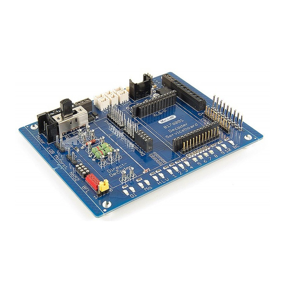
Page 5: Connections
Anschlußmöglichkeiten Connections (detaillierte Ansicht auf Seite 8+9) (detailed overview on page 8+9) Eingänge + Ausgänge Inputs + Outputs Erweiterte Anschlüsse Extended Connections Decoder Schnittstellen Decoder Interfaces LED Anzeige LED Display Abbildung 1: Licht- und Funktionsausgänge Illustration #1: Light- and Function Outputs 2.1 Decoder-Schnittstellen 2.1 Decoder Interfaces Die folgenden Schnittstellen sind... -
Page 6: Extended Connections
• 9pol. Steck-Schnittstelle • 9pin Plug-In Unterface für XLS, XL, XXL, usw. for XLS, XL, XXL, etc. • 10poliger DCC-Schnittstelle • 10pin DCC Interface für LGB 55027, usw. for LGB 55027, etc. • Directdecoder-Schnittstelle • Direct-Decoder-Interface für eMOTION L, L55021, usw. for eMOTION L, L55021, etc. - Page 7 Programming or Update (siehe Beschriftung) (check board printing) • Pufferanschluss (+,-,BC): • Buffer Connection (+,-,BC): Powercap-Anschluss (Massoth) Powercap Connection (Massoth) • Takt (Clk): Anschluß für einen digi- • Clock (Clk): Connection for a Hall talen Drehzahlgeber (824203x) Sensor (824203x) • Reedschalter (2K1): Anschluß für • Reed Contact (2K1): Connec-...
-
Page 8: Led Display
2.4 LED Anzeige 2.4 LED Display • Gleisspannung (Gl): Zeigt die • Track Voltage (Gl): Shows track Gleisspannung in beiden Polaritä- voltage in both polarities (both ten an (Bei Digital leuchten beide) LEDs will light when digital op.) • Motor (Mo): Zeigt die Richtung • Motor (Mo): Shows the direction des Motorausgangs an of the Motor Output... -
Page 9: Extended Connections
serienmäßig große Pufferkonden- for stable analog operations. In this case the electronic load may satoren für einen sicheren Analog- not be sufficient for the program- betrieb aber nicht reichen, das die ming procedures and an external Programmierimpulse sicher er- load (such as a motor) is required. zeugt werden. - Page 10 Takt Programmiergleis Clock Programming track Fahrgleis Pufferanschluss Track Powercap LGB Getriebeanschluss (4pol. Stecker) Reedkontakt LGB motor block connection Reed contact (4pole plug) Betriebsartenschalter Mode switch LGB Getriebeanschluss (einzel Kabel) LGB motor block connection (single cable) NEM652 Interface NEM652 Interface 8FL Decoder 8FL Decoder Last/Load Abbildung 2: Licht- und Funktionsausgänge...
- Page 11 Entkuppler SUSI Anschluss für externes Soundmodul Decoupler SUSI connector for ext. sound module autsprecher Servo Speaker Servo Unverstärkte LED8 Ausgänge/ LED7 Unreinforced Poti Update Anschluss Dec- outputs Poti Update Connection LED10 Verstärkte LED9 utsprecher 2 Ausgänge/ Speaker 2 LED6 Reinforced LED5 outputs Dec+...
-
Page 12: Update & Fastupdate
• Unverstärkte Ausgänge (A7, A8) • Unreinforced Outputs (A7, A8) for für beliebige unverstärkte Ausgän- any unreinforced function output. ge. Die Beschriftung der Ausgänge The lettering of the Outputs only zeigt nur, welche zugehörige LED shows with LED is assigned to aufleuchtet. Generell kann hier it. -
Page 13: Connection Examples
Anschlussbeispiele Connection Examples 3.1 XLS, XL, XXL Decoder 3.1 XLS, XL, XXL Decoders Powercap Servo Bsp.: rot = verstärkt grün = unverstärkt e.g.: red = reinforced green = unreinforced 3.2 XLS-M1, XL-M1 Decoder 3.2 XLS-M1, XL-M1 Decoders Powercap Servo Codierung Beachten Note Encoding... -
Page 14: Xls-P Decoders
3.3 XLS-P Decoder 3.3 XLS-P Decoders Powercap 3.4 PluG Decoder + Soundmodul 3.4 PluG Decoder + Sound Module Powercap Servo... -
Page 15: L Decoder, L55020, L55021
3.5 L Decoder, L55020, L55021 3.5 L Decoders, L55020, L55021 Die Anschlusskabel dürfen keinen Make sure the connecting cables Kurzschluss verursachen, am do not short circuit. It is prob- Besten die Kabel auf die Motor- ably best to connect them to steckerschnittstelle aufgestecken. -
Page 16: Warranty & Service
Abmessungen: 120 x 100 x 28mm (T/B/H) 100 x 28mm (T/B/H) Gewährleistung & Kundendienst Warranty & Service MASSOTH gewährt die Fehlerfrei- MASSOTH warrants this product heit dieses Produkts im Rahmen against defects in materials and der gesetzlichen Vorgaben, workmanship for one year from mindestens jedoch für 1 Jahr ab... -
Page 17: Hotline
Softwareprodukte rund um MASSOTH Produkte. Irrtümer und Änderungen vorbehalten. Hotline Hotline Gerne stehen wir Ihnen für We will be happy to answer your Rückfragen zu diesem Produkt zur questions about this product. Verfügung. Sie erreichen uns per You may reach us via eMail at: eMail unter: hotline@massoth.de... - Page 20 Massoth Elektronik GmbH QUALITY Frankensteiner Str. 28 · D-64342 Seeheim · Germany MADE IN FON: +49 (0)6151-35077-0 · FAX: +49 (0)6151-35077-44 GERMANY eMail: info@massoth.de · www.massoth.de RoHS 032377o COMPLIANT 991088 BDA 8176001 2016.12...
Need help?
Do you have a question about the 8176001 and is the answer not in the manual?
Questions and answers