Table of Contents
Advertisement
Quick Links
Advertisement
Table of Contents

Related Manuals for Durafly BRAVADO


Summary of Contents for Durafly BRAVADO
-
Page 2: Speci Cations
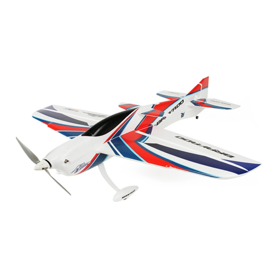
Features of the Bravado 1. ‘AirCore’ construction resulting in both a lightweight, yet strong structure. 2. Powerful set-up as standard for hardcore 3D and aerobatic performance. 3.Quick and easy assembly with minimum parts count. 4. Clean airframe design with easy battery access and generously sized control surfaces. - Page 3 Do not y under the conditions below • Strong winds (more than 20pmh) • Other storm like conditions • Area close to high voltage wires • Area with high density population Cautions for ying While parks make excellent ying areas, make sure you have permission to y there and follow safety guidelines set by local authorities.
- Page 4 Parts included in the packing 11.Landing gear 16. Tail wheel 12. Spinner 17. 1155 propeller 13. Screw (M4*30) 18. Rudder pushrod (φ1.2 piano wire) 14. Screw (M2*5) 19. Elevator pushrod (φ1.2 piano wire) 15. Adjustor 20. Aileron pushrod (φ1.2 piano wire) 21.
-
Page 5: Assembly Steps
Assembly steps 1. Aseembly begins with the wing (2) and fuselage (1). Incert the wing panel into the slot in the fuselage and glue in place. Insure that distance A is equal to B. 2. Hinges (4 for each side) can now be glued into the pre-cut slots of the trailing edge of the wing (2). - Page 6 3. Insert the fuselage winglet (5) into the upper fusealge slot and glue in place. Ensure distance C is equal to D. 4. The horizontal tail (17)can now be glued in place at the rear of the fusealge asr shown. Ensure distances E and F are equal and that the tail is horizontally level.
-
Page 7: Fuselage Assembly
Fuselage Assembly 5. Place vertial trailing edge insert (7) into pre-cut slot at the rear of fuselage, then x with glue. 6. Connect Z bend (18) to servo control horn on rudder (6), then push pushrod into pushrod tube. - Page 8 7. Glue 4 hinges into the rudder (6) then glue the rudder to the vertical tail (1) as shown below. 8. With the rudder in place the landing gear (11) can now be installed. Locate the supplied M4x25mm bolts (13) and secure to the fuselage (1) using a screw driver as shown. 9.
- Page 9 10. Locate the tail wheel assembly and install as detailed below using the supplied M2x5mm screws. 11. Install your 9g servo’s of choice into the molded pockets on the underside of the wing by guiding the wires through into the center of the fuselage and securing in place with some glue as shown below. KIT ONLY...
- Page 10 KIT ONLY 12. Glue the aileron control horn in place and connect the Z bend push rods (20) as shown. Ensure that your servo horns are at 90 degree’s to the wing at this stage. 13. Your 9g rudder and elevator servo of choice can now be glued in place in the pre-molded pockets on either side of the rear fuselage.
- Page 11 KIT ONLY 14. Both the rudder (not shown) and the elevator push-rod Z bend and control horn can now also be install just as before. Again ensure your servo horn is at 90 degree’s to the fusealge. 15 1 15. Install your choice of 2814 class motor onto the rewall as show below. It is suggested that thread lock be used.
- Page 12 16. Locate the spinner assembly and rst slide the spinner back plate (9) on the motor shaft followed by theprop (10), washer and nut as shown. Firmly tighen the nut and nishby screwing the spinner tip (9) in place. 17. Install your 30-40amp ESC of choice in the nose of the fuselage under the plastic battery tray as detailed below.
- Page 13 Assembly of your Dura y Bravado is now complete. Before you move onto the nal set-up of the model, we suggest you perform a nal check on all screws, bolts and components to ensure all are secture and rmly in place.
-
Page 14: Control Throws
1. With your receiver installed and all servos plugged into their corresponding channels, connect the ight battery to the ESC to power up the model. With the model now armed, ensure all servo’s are centered and all control surfaces are level. If not, adjust by turning the control clevis’s by hand accordingly until the control surfaces are level as shown. -
Page 15: Model Flying Precautions
With assembly and set-up now complete your Durafly Bravado should now be ready for flight. However we recommend you read and follow the advice given in thefollowing stages of this manual before flying your model. MODEL FLYING PRECAUTIONS: crowded areas Remember to keep clear of the propeller at all times when your flight battery is connected. - Page 16 Spare parts Rudder Canopy Winglet 9095000106-0 9095000115-0 9095000104-0 Stabilizer Fuselage 9095000102-0 9095000105-0 Spinner Landing gear Tail Wheel 9095000107-0 9095000107-0 9095000108-0 Control accessories set Sticker Set 9095000116-0 9095000113-0 Wing 9095000103-0...
Need help?
Do you have a question about the BRAVADO and is the answer not in the manual?
Questions and answers