Table of Contents
Advertisement
Advertisement
Table of Contents

Related Manuals for Durafly SUPERMARINE SPITFIRE MK24 V2


Summary of Contents for Durafly SUPERMARINE SPITFIRE MK24 V2
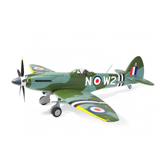
- Page 1 INSTRUCTION MANUAL...
- Page 2 WARNING! WARNING: Read the ENTIRE instruction manual to become familiar with the features of the product before operating. Failure to operate the product correctly can result in damage to the product, personal property and cause serious injury. This is a sophisticated hobby product and NOT a toy. It must be operated with caution and common sense and requires some basic mechanical ability.
-
Page 3: Table Of Contents
TABLE OF CONTENTS Kit contents The spare parts list Spare parts list content The illustration of the spare parts Charging the Flight Battery Low Voltage Cutoff Assemble the plane Install the control horn Connect the Y harness to the main wing Install the Horizontal stabilizer Test the electric device Band the receiver to the transmitter... -
Page 4: Kit Contents
7. Wing fairing The Spare parts list Replacement parts for the Durafly Spitfire are available using the order numbers in the Spare parts list that follows. The fastest, most economical service can be provided by your hobby dealer or mail-order company. -
Page 5: The Illustration Of The Spare Parts
112 Antenna mast 113 Canopy (Plastic canopy) 114 Motor shaft 115 X Motor base 116 Rear landing gear (With the tire) 117 Main landing gear strut (With the fairings and the tires) 118 Main landing gear system (E-retract with the strut and the tires) 119 E-retract 120 Decal sheet Note: All of the parts are painted with no decal applied. -
Page 6: Charging The Flight Battery
Charing the Flight Battery The Battery Charger is designed to safely charge the Li-Po battery, Caution: All instructions and warnings must be followed exactly. Mishandling of Li-Po batteries can result in fire, personal injury, or property damage. Battery warning: By handling, charging or using the included Li-Po battery you assume all risks associated with lithium batteries. -
Page 7: Assemble The Plane
Assemble the plane Install the Control horn 3. Check to make sure the screws are firmly Attached the control horn to the grabbed into the horns. starboard of the rudder with it toward the hinge line. 4. Install the aileron control horn on the servo side of the main wing with the horn towards the hinge line as the picture shows. -
Page 8: Connect The Y Harness To The Main Wing
Assemble the plane Install Control horn Connect the Y harness to the main wing 1. Attach the flap control horn on the servo 3. Connect the wing leads to the harness the side of the main wing with the horn first. -
Page 9: Install The Horizontal Stabilizer
Assemble the plane Install the Horizontal stabilizer 1. Insert the post side half stabilizer fully into place with the camouflage side face up, make sure insert the round bar into the glass fiber socket, the plastic bar with the eyelet into the square socket on the stabilizer root. -
Page 10: Test The Electric Device
Test the electric device Bind the receiver to the transmitter Before getting started, bind your receiver Receiver connection diagram. with your transmitter. Please refer to your Note: All servo and retract leads have Transmitter Manual for proper operation. been specifically labeled for your convenience. CAUTION: To prevent personal injury, Use the provided Y-harness for situations DO NOT install the propeller assembly... -
Page 11: Hook On The Linkage Rod Of The Stabilizer
Test the electric device Install the receiver 1. Slide the battery into the battery hatch 2. Snap the clevis into the elevator surface with the power supply cable toward the control horn. rear end of the plane and secure it using the pre installed hook and loop tape. - Page 12 Test the electric device 3. Adjust the linkage in the control connector to make sure the counterbalance leading edge of the elevator and the rudder level with the leading edge of the horizon stabilizer and the vertical fin respectively. Elevator up/Stick Down Note: Use a drop of thread lock on the screw before secure the rod into place.
-
Page 13: Install The Control Rod
Install the main wing Install the control rod 1. The standard hole settings for linkage 3. Toggle switch the flaps channel knob connections are shown by the black arrows according to which AUX port that the Y in the diagram below. You can refer the harness you have inserted into the receiver. -
Page 14: Install The Main Wing
Install the main wing Test the retract and the LED set 1. Cycle the retractable main landing gears several times to ensure proper function. 2. Apply glue to the radiator where it fits with the main wing using the glue brush or any other applicator. -
Page 15: Mount The Main Wing
Install the main wing 4. Verify the completed cannon installation. 2. Glue the fairing back into place. 5. Glue the air scoop into place. Mount the main wing 1. Install the main wing fairing fillet by fitting the proper one into place with no glue applied the first. - Page 16 Install the main wing Mount the main wing 1. Seat wing to the wing bay by threading the leads from the hole at the bottom of the wing bay to the receiver hatch, 2. Slightly pull the leads from the receiver hatch before fully fit the main wing into place to avoid any tangling to prevent the wing from fully mounting.
-
Page 17: Get Your Model Ready To Fly
Get your model ready to fly Important ESC and model information The ESC included with the Spitfire has a safe start. If the motor battery is connected to the ESC and the throttle stick is not in the low throttle or off position, the motor will not start until the throttle stick is moved to the low throttle or off position. -
Page 18: The Transmitter And Model Setup
Get your model ready to fly The transmitter and model setup Before getting started, rebind your receiver with your transmitter if necessary. CAUTION : To prevent personal injury, DO NOT install the propeller assembly onto the motor shaft while testing the control surfaces . Tips: Make sure all control sticks on your radio are in the neutral position (rudder, elevator, ailerons) and the throttle in the OFF position. - Page 19 Get your model ready yo fly 2. Re hec k to align the control surfaces well by trim the control channel. The ailerons align with the trailing edge of the wing tip. Alierons Elevator Rudder P.16...
-
Page 20: Check The Control Throws
Get your model ready to fly Check the control throws 1. Adjust ATV/travel adjustment on your transmitter until you obtain the following control surface travel. Do not adjust dual rates until you have correctly adjusted the total travel. Ailerons: 16mm up and down (both ailerons), measured at the aileron inboard side. Elevator: 14mm up and down, measured at the counterbalance leading edge. -
Page 21: Install The Propeller Set
Get your model ready to fly Get your model ready to fly Note: 1. This control throws were developed by R&D department for the best performance of the Spitfire. The small mount of elevator throw on low rate is capable of extreme aerobatics. -
Page 22: Install The Antenna Mast
Get your model ready to fly Get your model ready to fly 3. Install the spinner middle part. 4. Hand tighten the spinner and make sure it is tight enough and no gap left between the assembly. Install the antenna mast 1. -
Page 23: Check The C.g. (Center Of Gravity)
Get your model ready to fly Check the C.G. (Center of Gravity) Center of Gravity When balancing your model, adjust the motor battery as necessary so the model is level or slightly nose down. This the correct balance point for your model. After the first flights, the CG position can be adjusted for your personal preference. -
Page 24: Before The Model Flying
Before the model flying Find a suitable ying site Find a flying site clear of buildings, trees, power lines and other obstructions. Until you know how much area will be required and have mastered flying your plane in confined spaces, choose a site which is at least the size of two to three football fields – a flying field specifically for R/C planes is best. -
Page 25: Flying Course
Flying course Take off While applying power slowly steer to keep the model straight, the model should accelerate quickly. As the model gains flight speed, you will want to climb at a steady and even rate. The Spitfire will climb out at a nice angle of attack (AOA). Flying Always choose a wide-open space for flying your plane. -
Page 26: Troubleshooting
Troubleshooting Problem Possible Cause Solution Aircraft will not - Lower throttle stick and throttle - ESC is not armed. respond to the trim to lowest settings. - Throttle channel is reversed. throttle but responds - Reverse throttle channel on to other controls. transmitter.
Need help?
Do you have a question about the SUPERMARINE SPITFIRE MK24 V2 and is the answer not in the manual?
Questions and answers