Table of Contents
Advertisement
Advertisement
Table of Contents

Related Manuals for Durafly Curtiss P-40N


Summary of Contents for Durafly Curtiss P-40N
-
Page 1: Instruction Manual
Instruction Manual Please read this manual carefully before operating this plane. - Page 2 Read this instruction manual fully so as to become completely familiar with the features of this product before operating. Failure to operate this product correctly could result in damage to the product, personal property and cause serious injury. This is a sophisticated hobby product and is NOT a toy.
-
Page 3: Table Of Contents
CONTENTS Introduction Specifications Contents Of Box Required To Complete Model Assembly Setting Up Your Model 10-12 CG and battery placement 12-13 Model Flying Precautions Pre-flight Checks Flying Your P-40N P-40N General Tips Spare Parts Listing Decal Application Guidelines 17-18 Decal Tips American USAAF Markings 19-21 British RAF Markings... -
Page 4: Introduction
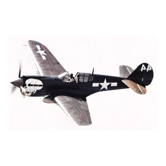
Durafly 1100mm warbird, a power train suitable for both 3 and 4S set-up’s with no modifications required. -
Page 5: Contents Of Box
8. Decal Sets REQUIRED TO COMPLETE MODEL In its ‘Plug n Fly’ format the Durafly P-40N requires some additional electronic components to get it flight ready. Durafly recommends the products below for optimum performance and great value. Available at hobbyking.com... -
Page 6: Assembly
NOTE: Your P-40N comes with a selection of scale decals/markings to choose from. Application of these decals is highly recommended BEFORE you begin assembly of the model. Please refer to ‘Decal application’ on pages 17-18 of this manual for illustrated guides on how to apply each set. - Page 7 3. Repeat this process for the rudder and elevator control horns, ensuring the screws tighten firmly into the control horn plate on the opposite side of each control surface. 1.7x15mm 1.7x15mm...
- Page 8 4. Insert that carbon tail spar into one half of the horizontal tail and slide into the opening at the rear of the fuselage ensuring the plastic screw tabs key fully into the fuselage sides. Repeat with the second half and once aligned, screw firmly in place with the 3x8mm screws as shown. A little glue may be applied at this stage for added security if desired.
- Page 9 6. Attach the wing to the fuselage and ensure the servo wires from the wing pass through only the 3rd hole from the rear of the plywood tray into the fuselage. This will ensure the wing sits correctly on the fuselage.
- Page 10 8. Slide the assembled back plate and blades onto the motor shaft ensuring the back plate keys properly onto the base of the shaft. Fit the supplied washer then nut onto the shaft and tighten the nut firmly to the shaft. 9.
- Page 11 9. Using a small amount of the glue supplied, glue the longer aerial into the slot behind the canopy, the short aerial into the slot of the battery hatch and the pitot tube onto the leading edge of the left wing panel as illustrated below.
- Page 12 The bomb release system is covered on page 12 of this manual. Assembly of your Durafly P-40N is now complete. Before you move onto the final set-up of the model, check all screws,...
-
Page 13: Setting Up Your Model
SETTING UP YOUR MODEL 1. With your receiver installed and all servos plugged into their corresponding channels, connect the flight battery to the ESC to power up the electronics. With the model now armed, ensure all servos are centered and all control surfaces are level. If not, adjust by turning the control clevis’s by hand accordingly until the control surfaces are level as shown. - Page 14 3. The P-40N handles very well in flight but requires setting up beforehand. Please follow the recommended settings below for good all round flight performance. 15-35mm 10-20mm 10-20mm 15-35mm Rudder 55-65mm 12-20mm 12-20mm * Elevator ‘low rates’ 10mm ‘high rates’ 20mm in either direction from neutral. * Aileron ‘low rates’...
-
Page 15: Cg And Battery Placement
5. Your P-40’s scale bomb drop system operates via a 2 position aux switch on your radio. With the bomb drop servo connected to the corresponding channel on your receiver, ensure that the bomb holds firmly (but without any servo strain) in position 1 of the switch and drops freely in position 2. If not, adjust the travel/end points on this aux channel until satisfied. - Page 16 Battery and receiver location Battery angle required for correct CG positioning With assembly and set-up now complete, your Durafly P-40N should now be ready for flight. However we recommend you read and follow the advice given in the following pages of this manual...
-
Page 17: Model Flying Precautions
MODEL FLYING PRECAUTIONS ● Select your flight area carefully. Always choose an open space that is unobstructed from trees and buildings and away from crowed areas. Avoid flying in area’s with roads, electric/telephone poles/wires and water near by or within close proximity to full size air traffic. ●... -
Page 18: Flying Your P-40N
FLYING YOUR P-40N Before flying make sure you have followed closely the set-up guidelines on pages 10 through 13. Start by taxying on the ground a little to get use to the handling. Be sure to always taxi with full up elevator held in, flaps retracted and gentle use of throttle. -
Page 19: P-40N General Tips
● Do not leave your model in direct sunlight for prolonged periods of time. This will have an adverse effect on the foam surface of the model. Thank you again for purchasing the Durafly P-40N. We hope you’ll have many happy days of flying and look forward to bringing you more Durafly models in the future. -
Page 20: Spare Parts Listing
SPARE PARTS LISTING Fuselage Main wing inc bomb servo Horizontal tail Part No.: 9306000190-0 Part No.: 9306000191-0 Part No.: 9306000192-0 Bomb Propeller set Scale plastic parts Part No.: 9306000195-0 Part No.: 9306000193-0 Part No.: 9306000194-0 Spinner set Prop shaft Battery hatch Part No.: 9306000196-0 Part No.: 9306000203-0 Part No.: 9306000197-0... -
Page 21: Decal Tips
4. Position the decals carefully on the model according to the decal reference sheet then gently rub (using a dry cloth) the decal in place rubbing from the center of the decal out to avoid wrinkles and air bubbles. 5. If you do have some air bubbles under the decal, use the tip of a sharp blade to make a small hole in the bubble then rub over it again to push the air out. - Page 23 DECAL SET...
-
Page 24: Decal Set
DECAL SET... -
Page 37: Propeller Decals
Propeller decals... -
Page 38: Trouble Shooting
TROUBLE SHOOTING: Problem Cause Solution 1. Charge the batteries. 1. Battery is not fully charged. 2. Install a full charged battery. 2. Transmitter battery low. 3. Check for connection 3. Motors not connected. between the ESC and motor. 4. Replace motor. Motor does 4. - Page 39 NOTES:...
- Page 40 facebook.com/durafly...
Need help?
Do you have a question about the Curtiss P-40N and is the answer not in the manual?
Questions and answers