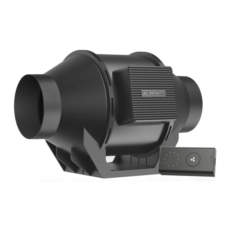
AC Infinity CLOUDLINE A4, CLOUDLINE A6, CLOUDLINE A8, CLOUDLINE H4 Manual
- User manual (37 pages) ,
- User manual (16 pages) ,
- User manual (41 pages)
Advertisement
- 1 WELCOME
- 2 INTERFERENCE from MH and HPS LIGHTS
- 3 KEY FEATURES
- 4 PRODUCT CONTENTS
- 5 INSTALLATION
- 6 POWERING AND SETUP
- 7 CONTROLLER MOUNTING
- 8 UISTM PLATFORM
- 9 UISTM COMPATIBILITY
- 10 ADDING MORE FANS
- 11 ADDING MORE DEVICES
- 12 CLEANING
- 13 PROGRAMMING
- 14 CLOUDLINE FAQ
- 15 AC INFINITY PRODUCTS
- 16 PRODUCT WARNING
- 17 Documents / Resources
WELCOME
We are committed to product quality and friendly customer service. If you have any questions or suggestions, please don't hesitate to contact us. Visit www.acinfinity.com and click contact for our contact information.
| EMAIL support@acinfinity.com | WEB www.acinfinity.com | LOCATION Los Angeles, CA |
INTERFERENCE from MH and HPS LIGHTS
Certain grow light models with HID* ballasts that do not use electromagnetic shielding will create an area of radio frequency interference (RFI). This can distort nearby frequency-sensitive components like internet lines and climate sensors. RFI can be emitted from the ballast's cords or the ballast itself.
Follow these steps to ensure proper functionality and to prevent radio frequency interference from affecting your sensor probe:

TIP 1
Keep the probe cord far away from your ballast's cords to ensure the controller properly detects climate conditions.
You may also wrap the probe cord and create a cone around the sensor head with aluminum foil tape.
TIP 2
Do NOT plug your grow light and inline fan into the same duplex outlet. Plug your grow light and inline fan into separate power strips and electrical sockets.
*MH, HPS, CMH, or CHPS
KEY FEATURES

*IP65 rated for H-Series
PRODUCT CONTENTS


INSTALLATION
MOUNTING
- Unscrew the bolts on both sides from the plastic rings using a Phillips screwdriver.

- Remove the motor box from the flange bracket. Remove the wind circle between the motor box and the intake flange.

- Use the flange bracket to set your desired fan position. Mark the four mounting holes.

- Drill four holes into the marked locations. Make sure your mounting area is structurally sound and free from obstruction.

- If you are mounting onto anything other than a wood support or stud, insert the included four wall anchors into the drilled mounting holes. You may need to use a hammer to secure them through the holes.
![]()
- Align the flange bracket's holes with the wall anchors. Screw in four wood screws with a screwdriver or drill to secure the flange bracket. Make sure its airflow arrow is pointing in your desired direction.
![]()
- Place the wind circle back into the intake flange.

- Slide the motor box back into the flange bracket, making sure its airflow arrow is pointing in the same direction as the flange bracket's arrow. Screw the bolts back into the plastic rings to secure the motor box to the flange bracket.

- If installing ducting, use duct clamps (sold separately) to secure it to either end of the duct fan, making sure there is a tight seal. Tighten the duct clamps using a flathead screwdriver.


HANGING - STRAPS
- Loop the strap around the bracket and a pole.
![]()
- Slip the strap through the inner ladder lock slot from the bottom.
![]()
- Route the strap into the outer ladder lock slot from the top. Adjust the length of the completed loop as needed.

- Tuck the loose end through the center gap of the ladder lock to secure the loop.
![]()
-
- Hanging Downward
Let the fan hang by the pole once the straps are secure. Make sure the fan's airflow arrow is pointing towards your desired direction.

- Hanging Upward
To hang the fan right-side up, loop and tighten the straps, as shown in steps 1-4, around the pole. Hang the fan by the duct flanges to secure it.

- Hanging Downward


HANGING - ROPE CLIPS
HANGING UPWARD
If installing with rope hangers (sold separately), loop the ropes around the flanges and tighten the rope to secure the fan.

HANGING DOWNWARD
Loop the two rope hangers around a pole and the fan's bracket. Clip the carabiners onto each other. Shorten the loops as needed. Make sure the fan's airflow arrow is pointing towards your desired direction.

MOTOR CAP
- Unscrew the motor cap using a screwdriver.

- Rotate the motor cap to your desired orientation. Reapply the screws. Rotating the motor cap will not void your warranty.


CONFIGURATION SETUP
INTAKE AND EXHAUST
This fan can be used as either an intake fan or an exhaust fan in grow rooms and larger grow tents. To achieve optimal whole space ventilation, the intake fan or opening - if not using a fan - must be situated at a bottom corner of your grow space. The exhaust fan must be hung (shown below) or mounted at the highest opposite corner possible.
Make sure the intake fan's airflow arrow is pointing towards your grow space and the exhaust fan's arrow points away from your grow space.

POWERING AND SETUP
- Use the included UIS M-M extension cord to connect the fan to the speed controller's port at the bottom.

- Plug the fan's power cord into a wall outlet. The controller will receive power from the fan to operate (EC Motor fans only).

- You may use the included tie mounts, wood screws, and wire ties to manage the cords. Secure the tie mounts onto a surface using the wood screws or adhesive backing. Loop the wire ties around the cords into the tie mounts.


CONTROLLER MOUNTING
WALL MOUNTING
- Locate a spot free of obstruction and secure the anchor into your wall. Twist the wood screw into the anchors.
![]()
- Hang the controller onto the screw using the hole on the backside.
![]()


MAGNET MOUNTING
Mount the controller using the magnet located on its backside.

PLATE MOUNTING*
Screw the controller plate bolts into the slit on the upper half of the plate.
Hang the controller onto the bolts using the hole on the backside.
*Controller plate not included

UISTM PLATFORM
The UISTM platform enables you to connect a single central controller with several grow devices simultaneously. By creating this fully integrated system, you can power and program all your devices together or separately for optimized grow tent management.
Your grow system can be regulated using your controller hub or remotely on the AC Infinity app (paired with compatible controllers), where you will have access to automation programming and climate data.
You can also connect your favorite grow light and outlet device to integrate them into the UIS platform using our RJ11/12 adapter and control plug module.

Central controller and grow devices will be sold separately and may still be in development at the time of your purchase of this product.
UISTM COMPATIBILITY
MOLEX ADAPTER*
Use a Molex adapter to plug inline fans with 4-pin Molex connectors into this controller. Plug the fan's Molex connector into the adapter. Then plug the adapter into the controller.

EXTENSION CABLE
Use male-to-male UIS extension cords to connect devices with female UIS ports at an extended range from your controller. Included with UIS-compatible devices.

EXPANSION SPLITTER*
The expansion splitter will allow you to connect 4 devices to a single port and can support additional splitters to create up to 3 tiers of expansion ports. Intended for exclusive use with AC Infinity controllers with UIS ports.

*Not included
ADDING MORE FANS
The CONTROLLER 69 PRO (sold separately) is built with four ports that enable you to power and control multiple fans at the same time. Compatible with inline fans with EC motors only. See image below for a sample configuration.

MOLEX ADAPTER
Use a UIS to 4-pin Molex adapter* to connect your fan to the Universal Controller*. Plug your fan's UIS connector into the adapter. Then plug the adapter into your controller.
*Not included

ADDING MORE DEVICES
EXTENDING THE CHAIN
Plug the male end of the splitter* into your UIS controller. Connect a UIS device or power adapter to the first port of each tier to power your controller and the hub.
Ports 2-4 can connect to additional splitters or UIS devices. All devices plugged into this chain must be of the same type (ex. fans of any size) regardless of the length of the dongle chain.
This splitter is not compatible with UIS adapters such as the RJ11 Lighting Adapter.
*Not included

DAISY-CHAINING
Each of the included controller's ports can support up to 20 devices using a daisy-chain adapter (not included). All devices must be from the same series but can be of differing sizes.
Plug the male end of the daisy-chain adapter into your device.
Connect your UIS controller to the daisy-chain adapter's INPUT port using a M-M connector cord. Using an extension cord, attach the daisy-chain adapter's OUTPUT port to another adapter's INPUT port. You can also link the OUTPUT port to another UIS device to end the chain.

CLEANING
- Remove the motor box from the mounting flange. Refer to steps 1-2 to learn how to remove the motor box.

- Use a damp cloth to clear the impeller and fan blades of any dust and debris. Remove the wind circle in between the motor box and input flange.

- Clear the stator blades of any dust and debris on the opposite end. Clean the area inside the output and exhaust flanges.

- Secure the motor box onto the mounting flanges. Refer to steps 7-9 to learn how to secure the motor box.


PROGRAMMING
FAN SPEED ADJUSTING
The controller features a single button that controls the fan speed from 0-10. Pressing the speed button increases the fan speed in one unit increments. Pressing the button at the 10 setting will set the fan speed back to 0.

POWERING ON/OFF
Press the button to turn your fan on. Hold the button to turn your fan off. Pressing it again will turn the fan on at its last speed setting.

CLOUDLINE FAQ
Q: I am missing my controller. It wasn't included in my package!
A: Please refer to an image of what your controller should look like. Your controller should be neatly slotted in the box by this product manual.
Q: Where is the best place to position the sensor probe?
A: Place the sensor probe as close as possible to the hottest or most humid spot in your space.
Q: Do I need to remove the plastic cap from the probe?
A: Yes. You will need to remove the plastic cap so the probe can accurately read climate conditions.
Can I mount this inline duct fan vertically?
A: Yes. The CLOUDLINE can be mounted in any orientation, including vertically.
Q: Will I be able to hardwire this fan to my own controller or thermostat?
A: We do not recommend hardwiring or splicing our fan's power wires. Such modifications may compromise electrical safety and will void this product's warranty.
Q: Do I need to use a power converter if I'm outside the US?
A: This product's voltage range is 100-240V AC. You may need a simple travel adapter to plug it into a foreign socket, or a power converter if your country uses a different voltage.
Q: Does the controller retain its settings after power is shut off?
A: Yes. If the controller's power is cut off and is powered on afterwards, your settings will remain.
Q: I'm not getting enough airflow even after setting the fan speed to 10. What can I do?
A: Bends in ducting will reduce your fan's CFM performance. To retain airflow, you may straighten the ducting and eliminate as many bends as possible.
Q: Should I use this inline duct fan as an intake or an exhaust fan?
A: The CLOUDLINE is primarily used as an exhaust fan, but can be used as an intake fan as well.
You may use this fan as an intake fan if you need fresh air into your space.
Q: Can I connect different sized fans to the same controller?
A: Please refer details on connecting fans together.
Q: I'm hanging my fan upside down in my grow tent, can I rotate its motor box plate?
A: Yes. Use a screw driver to unscrew the motor cap. Rotate it to your desired orientation and reapply the screws.
AC INFINITY PRODUCTS
Advance Grow Tents
The CLOUDLAB series is a line of grow tents designed to create ideal growing conditions and facilitate indoor plant cultivation year-round. Features 2000D thick oxford canvas lined with inner diamond patterned mylar that maximizes grow light luminosity, and a reinforced frame with 150 lb. weight capacity. Includes a mounting plate to install your AC Infinity controller onto.

Carbon Filter
The duct carbon filter is designed to eliminate odors and chemicals for grow tents and hydroponic spaces. It utilizes premium grade Australian charcoal that features greater absorption power and a longer lifespan. Enables maximum airflow to pass through as part of an intake or exhaust system.

Ducting Tubes
The four-layer ducting tube is used to direct airflow, designed for ventilation systems in applications like HVAC, dryers, and grow rooms. It is highly durable and flexible, and can be used anywhere from tight spaces to wide open areas.
Discover the latest innovations in environmental controls at acinfinity.com

PRODUCT WARNING


TO REDUCE THE RISK OF FIRE, ELECTRIC SHOCK, OR INJURY TO PERSONS, OBSERVE THE FOLLOWING:
- Ensure your power source conforms to the electrical requirements of this product.
- Check your local code restrictions for additional safety measures that may be needed for a proper code compliant installation.
- Read all instructions before installing and using this product.
- If you are unfamiliar or have doubts about performing this product's installation, seek the services of a qualified, trained, and licensed professional. Inappropriate installation will void this product's warranty.
- This product must not be used in potentially hazardous locations such as flammable, explosive, chemical-laden or wet atmospheres.
- Ducted products must always be vented to outdoor areas.
- Do not cover power cords with rugs or other fabric materials.
- This product has rotating parts. Safety precautions should be exercised during the installation, operation, and maintenance of this product.
- Do not insert or allow fingers or foreign objects to enter any ventilation or exhaust openings as it may cause electric shock, fire, or damage to this product. Do not block or tamper with this product in any manner while it is in operation.
- Do not depend on the on/off programming as the sole means of shutting power from this product. Unplug the power cord before installing, servicing, or moving this product.
- Do not operate this product while its cord is damaged, or if it malfunctions, has been dropped, or is damaged in any manner.
Documents / Resources
References
Download manual
Here you can download full pdf version of manual, it may contain additional safety instructions, warranty information, FCC rules, etc.
Download AC Infinity CLOUDLINE A4, CLOUDLINE A6, CLOUDLINE A8, CLOUDLINE H4 Manual
Advertisement


Need help?
Do you have a question about the CLOUDLINE Series and is the answer not in the manual?
Questions and answers