AC Infinity CLOUDLINE Series User Manual
Mixed flow inline fan system
Hide thumbs
Also See for CLOUDLINE Series:
- User manual (37 pages) ,
- User manual (16 pages) ,
- User manual
Table of Contents
Advertisement
Quick Links
Advertisement
Table of Contents

Related Manuals for AC Infinity CLOUDLINE Series


Summary of Contents for AC Infinity CLOUDLINE Series
- Page 1 CLOUDLINE SERIES MIXED FLOW INLINE FAN SYSTEMS USER MANUAL USER MANUAL...
- Page 3 WELCOME Thank you for choosing AC Infinity. We are committed to product quality and friendly customer service. If you have any questions or suggestions, please don’t hesitate to contact us. Visit www.acinfinity.com and click contact for our contact information. EMAIL LOCATION support@acinfinity.com...
- Page 4 MANUAL CODE CLAB2312X1 PRODUCT MODEL UPC-A CLOUDLINE A4 AI-CLA4 819137021747 CLOUDLINE A6 AI-CLA6 819137021754 CLOUDLINE A8 AI-CLA8 819137021761 CLOUDLINE H4 AI-CLH4 819137024595...
-
Page 5: Manual Index
Page 25 Compatibility ................ Page 26 Adding More Fans ................. Page 27 Adding More Devices ..............Page 28 Cleaning ..................Page 30 Programming ................. Page 32 ....................Page 33 Other AC Infinity Products ............. Page 35 Warranty ..................Page 36... -
Page 6: Product Warning
PRODUCT WARNING TO REDUCE THE RISK OF FIRE, ELECTRIC SHOCK, OR INJURY TO PERSONS, OBSERVE THE FOLLOWING: Ensure your power source conforms to the electrical requirements of this product. Check your local code restrictions for additional safety measures that may be needed for a proper code compliant installation. - Page 7 INTERFERENCE from MH and HPS LIGHTS Certain grow light models with HID* ballasts that do not use electromagnetic shielding will create an area of radio frequency interference (RFI). This can distort nearby frequency-sensitive components like internet lines and climate sensors. RFI can be emitted from the ballast’s cords or the ballast itself.
-
Page 8: Key Features
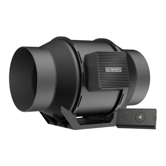
KEY FEATURES QUIET PWM MOTOR STATOR BLADE FANS SPEED CONTROLLER PWM-controlled motor Hydro-mechanical stator Single button controller features precise speed control, blades enable efficient with circular dot display that reduced rotor noise, and airflow delivery in high static enables fan speed control energy-efficient EC voltage. -
Page 9: Product Contents
PRODUCT CONTENTS DUCT FAN SPEED HANGING UIS M-M WOOD SCREWS SYSTEM CONTROLLER STRAPS CORD, 10 FT. (WALL MOUNT) (x1) (x1) (x2) (x1) (x1) HOOK AND ADHESIVE WIRE WALL DUCT FAN CONTROLLER LOOP TIES WIRE MOUNT MOUNT ANCHOR SCREW SET PLATE BOLTS (x4) (x1) (x6) - Page 10 PRODUCT CONTENTS...
-
Page 11: Installation
INSTALLATION MOUNTING STEP 1 Unscrew the bolts on both sides from the plastic rings using a Phillips screwdriver. STEP 2 Remove the motor box from the flange bracket. Remove the wind circle between the motor box and the intake flange. - Page 12 INSTALLATION MOUNTING STEP 3 Use the flange bracket to set your desired fan position. Mark the four mounting holes. STEP 4 Drill four holes into the marked locations. Make sure your mounting area is structurally sound and free from obstruction.
- Page 13 INSTALLATION MOUNTING STEP 5 If you are mounting onto anything other than a wood support or stud, insert the included four wall anchors into the drilled mounting holes. You may need to use a hammer to secure them through the holes. STEP 6 Align the flange bracket’s holes with the wall anchors.
- Page 14 INSTALLATION MOUNTING STEP 7 Place the wind circle back into the intake flange. STEP 8 Slide the motor box back into the flange bracket, making sure its airflow arrow is pointing in the same direction as the flange bracket’s arrow. Screw the bolts back into the plastic rings to secure the motor box to the flange bracket.
- Page 15 INSTALLATION MOUNTING STEP 9 If installing ducting, use duct clamps (sold separately) to secure it to either end of the duct fan, making sure there is a tight seal. Tighten the duct clamps using a flathead screwdriver.
- Page 16 INSTALLATION HANGING - STRAPS STEP 1 Loop the strap around the bracket and a pole. STEP 2 Slip the strap through the inner ladder lock slot from the bottom.
- Page 17 INSTALLATION HANGING - STRAPS STEP 3 Route the strap into the outer ladder lock slot from the top. Adjust the length of the completed loop as needed. STEP 4 Tuck the loose end through the center gap of the ladder lock to secure the loop.
- Page 18 INSTALLATION HANGING - STRAPS STEP 5(a) - Hanging Downward Let the fan hang by the pole once the straps are secure. Make sure the fan's airflow arrow is pointing towards your desired direction. STEP 5(b) - Hanging Upward To hang the fan right-side up, loop and tighten the straps, as shown in steps 1-4, around the pole.
- Page 19 INSTALLATION HANGING - ROPE CLIPS HANGING UPWARD If installing with rope hangers (sold separately), loop the ropes around the flanges and tighten the rope to secure the fan. HANGING DOWNWARD Loop the two rope hangers around a pole and the fan's bracket. Clip the carabiners onto each other.
- Page 20 INSTALLATION MOTOR CAP STEP 1 Unscrew the motor cap using a screwdriver. STEP 2 Rotate the motor cap to your desired orientation. Reapply the screws. Rotating the motor cap will not void your warranty.
-
Page 21: Intake And Exhaust
INSTALLATION CONFIGURATION SETUP INTAKE AND EXHAUST This fan can be used as either an intake fan or an exhaust fan in grow rooms and larger grow tents. To achieve optimal whole space ventilation, the intake fan or opening - if not using a fan - must be situated at a bottom corner of your grow space. - Page 22 POWERING AND SETUP STEP 1 Use the included UIS M-M extension cord to connect the fan to the speed controller’s port at the bottom. STEP 2 Plug the fan's power cord into a wall outlet. The controller will receive power from the fan to operate (EC Motor fans only).
-
Page 23: Controller Mounting
CONTROLLER MOUNTING STEP 1 — WALL MOUNTING Locate a spot free of obstruction and secure the anchor into your wall. Twist the wood screw into the anchors. STEP 2 — WALL MOUNTING Hang the controller onto the screw using the hole on the backside. -
Page 24: Magnet Mounting
CONTROLLER MOUNTING MAGNET MOUNTING Mount the controller using the magnet located on its backside. PLATE MOUNTING* Screw the controller plate bolts into the slit on the upper half of the plate. Hang the controller onto the bolts using the hole on the backside. - Page 25 By creating this fully integrated system, you can power and program all your devices together or separately for optimized grow tent management. Your grow system can be regulated using your controller hub or remotely on the AC Infinity app (paired with compatible controllers), where you will have access to automation programming and climate data.
-
Page 26: Extension Cable
COMPATIBILITY MOLEX ADAPTER* Use a Molex adapter to plug inline fans with 4-pin Molex connectors into this controller. Plug the fan's Molex connector into the adapter. Then plug the adapter into the controller. UIS M - 4PIN F ADAPTER EXTENSION CABLE Use male-to-male UIS extension cords to connect devices with female UIS ports at an extended range from your controller. - Page 27 ADDING MORE FANS The CONTROLLER 69 PRO (sold separately) is built with four ports that enable you to power and control multiple fans at the same time. Compatible with inline fans with EC motors only. See image below for a sample configuration. Multi-Fan Connection INLINE FAN 4"...
-
Page 28: Adding More Devices
ADDING MORE DEVICES EXTENDING THE CHAIN Plug the male end of the splitter* into your UIS controller. Connect a UIS device or power adapter to the first port of each tier to power your controller and the hub. Ports 2-4 can connect to additional splitters or UIS devices. -
Page 29: Daisy Chaining
ADDING MORE DEVICES DAISY-CHAINING Each of the included controller’s ports can support up to 20 devices using a daisy-chain adapter (not included). All devices must be from the same series but can be of differing sizes. Plug the male end of the daisy-chain adapter into your device. Connect your UIS controller to the daisy-chain adapter’s INPUT port using a M-M connector cord. - Page 30 CLEANING STEP 1 Remove the motor box from the mounting flange. Refer to steps 1-2 on page 11 to learn how to remove the motor box. STEP 2 Use a damp cloth to clear the impeller and fan blades of any dust and debris. Remove the wind circle in between the motor box and input flange.
- Page 31 CLEANING STEP 3 Clear the stator blades of any dust and debris on the opposite end. Clean the area inside the output and exhaust flanges. STEP 4 Secure the motor box onto the mounting flanges. Refer to steps 7-9 on page 14-15 to learn how to secure the motor box.
-
Page 32: Powering On/Off
PROGRAMMING FAN SPEED ADJUSTING The controller features a single button that controls the fan speed from 0-10. Pressing the speed button increases the fan speed in one unit increments. Pressing the button at the 10 setting will set the fan speed back to 0. Fan Speed Indicator POWERING ON/OFF... - Page 33 CLOUDLINE FAQ I am missing my controller. It wasn't included in my package! Please refer to page 9 for an image of what your controller should look like. Your controller should be neatly slotted in the box by this product manual. Where is the best place to position the sensor probe? Place the sensor probe as close as possible to the hottest or most humid spot in your space.
- Page 34 CLOUDLINE FAQ Does the controller retain its settings after power is shut off? Yes. If the controller's power is cut off and is powered on afterwards, your settings will remain. I'm not getting enough airflow even after setting the fan speed to 10. What can I do? Bends in ducting will reduce your fan's CFM performance.
- Page 35 150 lb. weight capacity. Includes a mounting plate to install your AC Infinity controller onto. Carbon Filter The duct carbon filter is designed to eliminate odors and chemicals for grow tents and hydroponic spaces.
-
Page 36: Warranty
WARRANTY This warranty program is our commitment to you, the product sold by AC Infinity will be free from defects in manufacturing for a period of two years from the date of purchase. If a product is found to have a defect in material or workmanship, we will take the appropriate actions defined in this warranty to resolve any issues. - Page 37 No part of the materials including graphics or logos available in this booklet may be copied, photocopied, reproduced, translated or reduced to any electronic medium or machine readable form, in whole or in part, without specific permission from AC Infinity Inc.
- Page 40 www.acinfinity.com...
Need help?
Do you have a question about the CLOUDLINE Series and is the answer not in the manual?
Questions and answers