Riello Condexa PRO NA 75 P Service Manual
Hide thumbs
Also See for Condexa PRO NA 75 P:
- Installation, operation and service manual (112 pages) ,
- User's information manual (36 pages)
Table of Contents
Advertisement
Condexa PRO North America
US INSTALLATION OPERATION AND SERVICE MANUAL
9
WARNING: If the information in this manual is not
followed exactly, a fire or explosion may result causing
property damage, personal injury or loss of life.
Do not store or use gasoline or other flammable
vapors and liquids or other combustible materials in
the vicinity of this or any other appliance. To do so
may result in an explosion or fire.
What to do if you smell gas:
- Do not try to light any appliance;
- Do not touch any electrical switch; do not use any
phone in your building;
- Immediately call your gas supplier from a neighbor's
phone. Follow the gas supplier's instructions;
- If you cannot reach your gas supplier, call the fire
department.
Installation and service must be performed by a
qualified installer, service agency or the gas supplier.
This manual should be maintained in legible
condition and kept adjacent to the boiler or in a safe
place for future reference.
Advertisement
Table of Contents

Related Manuals for Riello Condexa PRO NA 75 P


Summary of Contents for Riello Condexa PRO NA 75 P
- Page 1 WARNING: If the information in this manual is not followed exactly, a fire or explosion may result causing property damage, personal injury or loss of life. Do not store or use gasoline or other flammable vapors and liquids or other combustible materials in the vicinity of this or any other appliance.
- Page 2 , a qual- ity product that is designed to give dependable, efficient and safe MODEL CODE service and to provide comfort in the home for many years to Condexa PRO NA 75 P 20142594 come. Condexa PRO NA 117 P 20142595 This manual provides information that is essential to the in- stallation of the appliance.
-
Page 3: Table Of Contents
CONTENTS 1 GENERAL INFORMATION . . . . . . . . . . . . . . . . . . . . . . . . . . . . 5 2.11 System filling and emptying. - Page 4 5 SYSTEM MANAGEMENT . . . . . . . . . . . . . . . . . . . . . . . . . . . .86 Communication between the thermal modules .
-
Page 5: General Information
GENERAL INFORMATION GENERAL INFORMATION Periodically check that pressure in the central heating circuit, when cold, is approximately 20 psi and below the maximum limit specified for the boiler. 1.1 General Safety Information If the boiler is not going to be used for an extended period of time, perform the operations described later in this manual. - Page 6 GENERAL INFORMATION Do not plug or block the condensate drain outlet. NOTICE: Risk of appliance damage from improper operation of the boiler! Never pull, disconnect, or twist the electrical cables coming − Only use the boiler for its intended purpose. from the appliance even if it is disconnected from the mains −...
-
Page 7: Description Of The Appliance
GENERAL INFORMATION 1.3 Description of the appliance CAUTION: Appliance damage from contaminated combustion air! Condexa PRO NA it is a condensing, pre-mixed thermal module − Keep the combustion air free of corrosive substances, e.g. consisting in a modulating thermal element. halogenated hydrocarbons from painting operations or It's available in two models of power: 75 kW (255,900 BTU/hr) and beauty salons. -
Page 8: Safety Devices
GENERAL INFORMATION 1.4 Safety devices 1.5 Identification All appliance functions are electronically controlled by a dual pro- The products are identified by: cessor technology board approved for safety functions. Any malfunction results in the appliance being shut down and the automatic closure of the gas valve. -
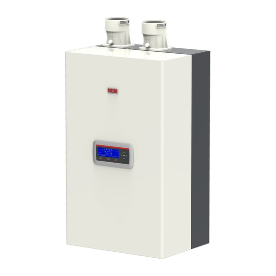
Page 9: System Layout
GENERAL INFORMATION 1.6 System layout Condexa PRO NA 75 P Flue gas exhaust connection Exhaust flue probe Gas valve Combustion chamber Electrical panel Smoke-exhaust flue non-return valve Drain cock Minimum Pressure Switch set at 0,5 bar 10 Pump Main switch... - Page 10 GENERAL INFORMATION Condexa PRO NA 117 P Flue gas exhaust connection Exhaust flue probe Combustion chamber Electrical panel Smoke-exhaust flue non-return valve Drain cock Minimum Pressure Switch set at 0,5 bar Pump 10 Main switch Central heating return 12 Gas supply 13 Central heating supply 14 Condensate drain connection 15 Flow-meter...
-
Page 11: Technical Specifications
GENERAL INFORMATION 1.7 Technical specifications Description Unit Condexa PRO NA 75 P Condexa PRO NA 117 P Boiler category ASME Section IV ASME Section IV Type of Gas Natural Gas, Propane* BTU/hr 255900 399204 Max input rate (kW) (75) (117) -
Page 12: Pumps
243,1 379,2 AFUE Combustion Efficiency 10,2 - 10,8 9,4 - 9,6 1.8 Pumps Thermal modules Condexa PRO NA 75 P and Condexa PRO NA 117 P are equipped with a circulator. H [f] 35,0 30,0 25,0 Heat exchanger Safety thermostat tem-... -
Page 13: Control Panel
GENERAL INFORMATION 1.11 Control panel CONTROL PANEL AND SYMBOLS 255x80 point backlit display (4.2" x 1.5") RESET key: restores normal operations after a safety shut-down MENU key: switches on the main menu ESC key: in menu navigation, it enables you to exit a menu item and go back to the previous one 5 ÷... -
Page 14: Regulations And Guidelines
GENERAL INFORMATION 1.12 Regulations and Guidelines − In the event that the side wall horizontally vented gas fu- eled equipment is installed in a crawl space or an attic, the hard wired carbon monoxide detector with alarm and bat- tery back-up may be installed on the next adjacent floor NOTICE: Observe all rules, regulations, standards and guide- level. -
Page 15: Venting And Air Piping System
GENERAL INFORMATION 1.13 Venting and air piping system The unit is to be used for either direct vent installation or for in- stallation using room air for combustion. When room air is used, it is necessary to provide an adequate opening for the fresh air intake. -
Page 16: Connecting Flue Gas Systems
− The diameters of the flue outlet and combustion air in- take inlet are designed to fit standard PP and stainless steel pipes. The following table gives the diameter of the flue adapter on the boiler. Condexa PRO NA 75 P Condexa PRO NA 75 P Diameters 4” - 100mm 4”... -
Page 17: Installation Of The Exhaust And Air Intake System
GENERAL INFORMATION 1.13.3 Installation of the exhaust and air intake system NOTICE: Do not extend exposed vent pipe outside the building beyond recommended distance of 39” or 1 meter. Condensate could freeze and block vent pipe. Vent should terminate at least 3 feet (915 mm) away from adjacent walls, inside corners and 5 feet (1525 mm) below roof overhang (1) - (2). - Page 18 GENERAL INFORMATION Approved Flue gas or combustion air materials and fittings per boiler Condexa PRO NA Condexa PRO NA Material Item Standard [USA] Standard 75 P 117 P ANSI Cat IV Approved Poly- Flue gas or combustion air 4” (100mm) 4”...
-
Page 19: Vent And Combustion Air Pipe Length [For Single Boiler Installations]
The maximum length for vent and combustion air pipes can be found in the following table. Please note the length is for each Condexa PRO NA 75 P vent/combustion air pipe and not combined. 3” System 4” System 5”... -
Page 20: Approved Examples Of Horizontal And Vertical Venting Installation
GENERAL INFORMATION 1.13.5 Approved examples of horizontal and vertical Horizontal venting system (room air only); X≥4” (102 mm) venting installation NOTICE: Place pipe supports every 5 feet (1,525 mm) of horizon- tal and vertical run, beginning with support near boiler. −... - Page 21 GENERAL INFORMATION Horizontal venting system (sealed combustion); X≥4” (102 Vertical venting system (sealed combustion); X > 12” ; Y 12” mm); Y ≥12” (305 mm) above maximum snow level or at least 24” whichever is greater Vertical venting system (sealed combustion); Y 12” above maximum snow level or at least 24”...
- Page 22 GENERAL INFORMATION Horizontal venting system (sealed combustion); 3 is a wall Horizontal concentric system (sealed combustion) termination Vertical venting system (sealed combustion); X > 12” (305 mm); Y 12” above maximum snow level or at least 24” which- ever is great Horizontal venting system (sealed combustion);...
-
Page 23: Multiple Boiler
GENERAL INFORMATION 1.13.6 Multiple boiler Vertical venting system (sealed combustion) When installing multiple air and vent terminations, be sure that: − The clearance between the vent and air termination are in accordance with the figures shown in this chapter − All vent pipes and air inlet must terminate at the same height Concentric vent and combustion air vertical termination;... -
Page 24: De-Rating For Altitude Installation
GENERAL INFORMATION 1.13.7 De-rating for altitude installation Multiple air and vent vertical termination; X≥ 12”; Y≥ 12” When the appliance is installed at an altitude higher than 2000 ft, refer to the regulations and authorities having jurisdiction. Air intake Vent % range of the length of the vent and Condexa PRO NA Vent... -
Page 25: Multiple Boiler Cascade System
Both common air intake and exhaust system (sealed com- bustion) Maximum length for air and combustion pipe for cascade of Condexa PRO NA 75 P Condexa PRO NA 6” (150 mm) 8” (200 mm) -
Page 26: Installation
The instruction manual is an integral part of the appliance; therefore, it should be read and stored carefully. Keep the documentation envelope in a safe place. Any re- placement documents must be ordered from Riello S.p.A. who reserve the right to charge for the cost of the replacement. -
Page 27: Installation Premises
INSTALLATION 2.3 Installation premises 2.4 Installation in older systems and systems requiring modernisation The thermal module Condexa PRO NA can be installed in rooms that are permanently ventilated and equipped with suitably sized When installing these boilers in older systems or systems requiring ventilation openings in line with Technical Standards and Regula- modernisation, always perform the following checks: tions applicable to the installation site. -
Page 28: Thermal Module Assembly
− remove the locking screw − pull the front panel outwards and then to the top to de- couple it from points A. Model Height (H) ft Condexa PRO NA 75 P 6<H<6.5 Condexa PRO NA 117 P 6<H<6.5 For installation: −... -
Page 29: Water Connections
INSTALLATION 2.7 Water connections The dimensions and position of thermal module's hydraulic connections are shown in the table below. Front view Bottom view DESCRIPTION Condexa PRO NA 75 P Condexa PRO NA 117 P 15.2 15.2 inch inch inch 11.1 11.1... -
Page 30: Typical Water System Schematics
INSTALLATION 2.8 Typical water system schematics Layout 1: circuit with thermal module directly linked to heating system (check that the pump's discharge head is sufficient to ensure adequate circulation) CONDEXA PRO North America Layout 2: circuit with thermal module directly linked to heating system and DHW tank. (check that the pump's discharge head is sufficient to ensure adequate circulation) CONDEXA PRO North America... - Page 31 INSTALLATION Layout 3: circuit with thermal module connected to a heating system via a separator CONDEXA PRO North America Layout 4: circuit with thermal module linked to DHW tank and heating system via a separator CONDEXA PRO North America 1 7 8 Isolating valve 10 Automatic bleed valve Outdoor sensor...
- Page 32 INSTALLATION Layout 5: circuit with thermal module linked to heating system and DHW. tank via a separator CONDEXA PRO North America 1 7 8 Isolating valve 10 Automatic bleed valve Outdoor sensor Non-return valve Diverter valve High temperature DHW circulation pump 12 Pump system flow Expansion tank...
-
Page 33: Gas Connections
INSTALLATION 2.9 Gas connections On completion of the installation, check that all joints are sealed. The gas connection must be made respecting the installation reg- ulations in force, and sized to ensure the correct gas delivery to the burner. Before making the connection, check that: The gas type is suitable for the appliance If the appliance needs to be adapted for use with another gas fuel, contact your local Technical Assistance Service to have... - Page 34 3.3ft 9.8ft The table with available residual discharge heads is shown below. Discharge head Description 6.3 mbar - 0.35 mbar - Condexa PRO NA 75 P 0.21 feet head 0.01 Condexa PRO Condexa PRO 0.32 mbar - DESCRIPTION Condexa PRO NA 117 P 6.1 mbar - 0.2...
-
Page 35: Preparation For The Condensate Drain
INSTALLATION 2.10.1 Preparation for the condensate drain Fill the siphon with water before activating on the thermal module in order not to release any combustion products into The exhaust of the condensation produced by the appliance Con- the environment when the thermal module is first switched dexa PRO NA during its normal operation, must be carried out with an accessory (siphoned condensate collector) that needs to be installed below the thermal module itself as specified in its... -
Page 36: System Filling And Emptying
INSTALLATION 2.11 System filling and emptying Water hardness must fall within the following limits: 50 ppm of CaCO < (alkali strength) < 150 ppm of CaCO − Use only untreated water to fill the system. The thermal module Condexa PRO NA must be provided with a −... -
Page 37: Emptying
INSTALLATION 2.11.2 Emptying − Unscrew the vent valve's release cap − Open the shut-off cocks in order to slowly fill the system − Use the pressure gauge to check that the pressure is rising Before starting to empty the appliance and the storage cylinder: and the water is exiting through the vent valves −... -
Page 38: Wiring Diagram
INSTALLATION 2.12 Wiring diagram J6-3 J6-10 J6-12 J6-5 J7-3 b J7-2 h J7-2 J7-4 J12-4 J12-1 J7-6 J7-7 J7-8 J12-2 J12-5 J21-1 / J6-1 J21-5 / J6-2 J21-4 / J6-8 J21-6 J21-3 10 11 12 13 14 15 16 17 18 0-10V RT Modbus BUS 1... - Page 39 INSTALLATION J2-1 J2-2 J2-4 J1-4 J1-5 J1-1 J2-6 J3-5 J3-10 J4-2 J4-3 J4-6 J4-5 J4-4 J4-1 J5-2 J5-1 J3-1 J3-7 J3-2 J3-3 J3-8 J3-4 J2-3 J3-9 J3-6 bl 101 102 103 104 105 106 107 108 109 110 111 112 113 114 115 PS (120V ~ 60Hz) Thermal module circulator Cable colour...
-
Page 40: Electrical Connections
INSTALLATION 2.13 Electrical connections Before connecting any external electrical components to the appliance (regulators, electric valves, climate control probes, The thermal module Condexa PRO NA is manufactured fully wired etc.), check to make sure that their electrical characteristics and only needs to be connected to the mains, the room/heat de- are compatible with the available inputs and outputs (volt- mand thermostat and any other system components. - Page 41 INSTALLATION Loosen the fixing screws (2) and remove the protection (3) For connection, see the following figure: ~ 120 V 101 102 103 104 105 106 107 108 109 110 111 112 113 114 115 Circuit breaker Relay / Switch (120V AC) Refer to the device type for the supply tension.
- Page 42 INSTALLATION Electrical wiring referred to layout 2 at page "30". Electrical wiring referred to layout 4 at page "31". 10 11 12 13 14 15 16 17 10 11 12 13 14 15 16 17 101 102 103 104 105 106 101 102 103 104 105 106 0-10V Modbus...
-
Page 43: Electronic Control
INSTALLATION 2.14 Electronic control The electronic control operator interface menu is a multi-level one. Navigation between the various levels is shown in the figures below. Level 0 displays the Home Screen (Home). Level 1 displays the Main Menu screen. The subsequent levels are activated depending on available sub-menus. -
Page 44: Menu Structure
INSTALLATION 2.14.1 Menu structure... - Page 45 INSTALLATION...
- Page 46 INSTALLATION...
- Page 47 INSTALLATION...
- Page 48 INSTALLATION...
- Page 49 INSTALLATION...
-
Page 50: Parameters' List
INSTALLATION 2.14.2 Parameters' list Parameters are listed base on the reference menu. Reference Menu Access type Parameters Menu End user Cascaded module configuration menu Installer Cascaded boiler configuration menu Manufacturer Appliance configuration menu Nr. dis- Par. Default Access Menu played Description Range Category... - Page 51 INSTALLATION Nr. dis- Par. Default Access Menu played Description Range Category setting type Display Hx Diff. Max. Defines the restart time after reaching the Delta T 10…250 Sec. General Wait limit between delivery and return. Time Max. Power Sets the heating's % max. power. 50…100 Heating Min.
- Page 52 INSTALLATION Nr. dis- Par. Default Access Menu played Description Range Category setting type Display Tank Defines the hysteresis to initiate the domestic hot °F 0…20 41 (5) Hyst. water demand. (°C) Down Defines the hysteresis to stop the domestic hot °F Tank 0…20...
- Page 53 INSTALLATION Nr. dis- Par. Default Access Menu played Description Range Category setting type Display Speed Defines the number of fan rpm at minimum power Defined 0…12750 General Mini- (it depends on the model and is defined at Par. 98). by Par. 98 Defines the number of fan rpm when the boiler is Defined Speed...
- Page 54 INSTALLATION Nr. dis- Par. Default Access Menu played Description Range Category setting type Display 0 Disabled 1 General Pump 2 CH Pump 3 DHW Pump 4 System Pump 5 Cascade Pump Prog. 6 Alarm Relay Defined Output The value of this parameter is defined by Par. 97. 7 Filling Valve General by Par.
- Page 55 INSTALLATION Nr. dis- Par. Default Access Menu played Description Range Category setting type Display Activates bleeding the system's air. To activate air bleeding, it is necessary to switch on the boil- er and change the parameter from "No" to "Yes". Wait for one minute.
- Page 56 INSTALLATION Nr. dis- Par. Default Access Menu played Description Range Category setting type Display Defines by how many degrees the temperature Hyst. Up measured by the primary circuit's probe must go °F Quick above the set-point in order for the subsequent 0…40 42.8 (6) Cascade...
- Page 57 INSTALLATION Nr. dis- Par. Default Access Menu played Description Range Category setting type Display Pwr- Defines the extra power value (in percentage terms) Mode2 compared to the average power of all on modules in 0…100 Cascade Hyster- cascade operation mode (Par. 148 = 2). esis Post- Defines overrun time in seconds at the end of the...
-
Page 58: Configuration Of The Main Block Diagrams
CONFIGURATION OF THE MAIN BLOCK DIAGRAMS 3 CONFIGURATION OF THE MAIN BLOCK DIAGRAMS RT / OS / 0-10V The DHW and heating circuits must be completed with ex- DEPENDING MANAGING pansion vessels of a suitable capacity and correctly sized relief valves. -
Page 59: Configuration Of The Secondary System
CONFIGURATION OF THE MAIN BLOCK DIAGRAMS 3.2 Configuration of the secondary system For the sake of simplicity, the hydraulic circuits downstream of the separator can be identified as the secondary system. Optimal use of the modules in cascade occurs by placing a hy- The basic configuration of the secondary system takes place using draulic separator (available as an accessory) between the primary a system circulator (CHP). -
Page 60: Block Diagram 1
CONFIGURATION OF THE MAIN BLOCK DIAGRAMS 3.3 Block diagram 1 Circuit with thermal modules with their own circulator, connected in cascade. DEPENDING DEPENDING MANAGING Thermal module circulator Storage cylinder circulator DHW circulation pump System circulator (high temperature zone) DHW Boiler sensor Outdoor sensor Primary sensor Domestic cold water inlet... -
Page 61: Sensor Connections Block Diagram 1
CONFIGURATION OF THE MAIN BLOCK DIAGRAMS 3.3.2 Sensor connections Block diagram 1 3.4 System parameters Block diagram 1 MANAGING CONNECTIONS See the section "Putting into service and maintenance" for a detailed description on parameter operation MANAGING Essential parameters to be configured for the block diagram 1: 10 11 12 13 14 15 16 17 18 Managing Depending... -
Page 62: Block Diagram 2
CONFIGURATION OF THE MAIN BLOCK DIAGRAMS 3.5 Block diagram 2 Circuit with thermal modules with their own circulator, connected in cascade. Using the secondary sensor. DEPENDING DEPENDING MANAGING Thermal module circulator Domestic cold water inlet Storage cylinder circulator Domestic hot water outlet DHW circulation pump System circulator (high temperature zone) DHW Boiler sensor... -
Page 63: Sensor Connections Block Diagram 2
CONFIGURATION OF THE MAIN BLOCK DIAGRAMS 3.5.2 Sensor connections Block diagram 2 DEPENDING CONNECTIONS MANAGING CONNECTIONS DEPENDING MANAGING 10 11 12 13 14 15 16 17 18 10 11 12 13 14 15 16 17 18 0-10V RT Modbus BUS 1 LWCO BUS 2 0-10V RT... -
Page 64: Commissioning And Maintenance
COMMISSIONING AND MAINTENANCE 4 COMMISSIONING AND MAINTENANCE Confirm with the ● key and select "Date and Time " with the ▲ / ▼ keys 4.1 Initial startup General Settings “ ” Language − Switch the system's master switch to the ON position and “... -
Page 65: Password Access
COMMISSIONING AND MAINTENANCE Enter one digit at a time using the ▲ / ▼ keys to increase/decrease To change the way in which date and time are displayed, it is pos- sible to change the following characteristics by accessing the "Dis- the numeric value. - Page 66 COMMISSIONING AND MAINTENANCE The parameters regulating such temperature are: Par. Delivery Temp. Description °F (°C) Tset max °F (°C) Par. 24 Sets the desired flow temperature with heating mode. Active for the heating mode Par. 1 = 0 o 3 Limits the minimum value that can be assigned to the Par.
- Page 67 COMMISSIONING AND MAINTENANCE Mode 2 Mode 3 (Working on climatic mode with attenuation controlled by a room/ (Continuous fixed set-point operation with attenuation controlled heat demand thermostat, variable set point according to the out- by room/heat demand thermostat) door temperature) In this mode the fixed set-point is adjusted in the same way as described for Mode 0.
-
Page 68: Setting The Domestic Hot Water Parameters
COMMISSIONING AND MAINTENANCE 4.1.5 Setting the domestic hot water parameters Mode 4 (Set-point adjustment based on a 0-10V analogical input) The parameter 35 defines the various operation modes of the The parameters that control this mode are the following: thermal module for DHW production Par. -
Page 69: Scheduled Programme
COMMISSIONING AND MAINTENANCE − Use the ► key to highlight the value, and use the ▲ / ▼ Priority setting keys to change the selected value. Press the ● key to con- firm/save the new settings.. The parameter 42 sets the priorities between the DHW and CH cir- cuit. - Page 70 COMMISSIONING AND MAINTENANCE Holiday Programme Heating programming The Holiday Programme is used to exclude part of or all the circuits at a certain time of the year. Group A holiday can be set both on the full system and on various groups “...
- Page 71 COMMISSIONING AND MAINTENANCE DHW setting Set-points outside the interval Selection of the type of set-point to be used when a zone is not on a set period by selecting between: Group − Off “ ” Program Comfort Period − On “...
-
Page 72: Thermal Module Information
COMMISSIONING AND MAINTENANCE As part of group selection, the Holiday Group is displayed with the − At date: excludes heating (CH+zone) when the current date following parameters: is included between the start and the end dates. − Holiday set-point: Set-point type to be used for the se- lected group. -
Page 73: Checks During And After Initial Start-Up
COMMISSIONING AND MAINTENANCE By selecting "Maintenance" and pressing the ● key, the following The display shows four lines at a time. You can scroll the list by values are displayed: using the ▲ / ▼ keys. − Maintenance log (each time a "Maintenance reminder re- set"... -
Page 74: Error List
Nominal supply 0.4-0.43 0.53 pressure Condexa PRO NA 75 P Condexa PRO NA 117 P After the checks: − select "OFF" with the ▲ / ▼ keys and press ● to confirm. − Disconnect the pressure gauge and tighten again the pres- sure test point screw (1) upstream from the gas valve. -
Page 75: Permanent Errors
COMMISSIONING AND MAINTENANCE 4.3.1 Permanent Errors Error Description REFHI_TOO_HIGH / REFHI_ Internal software error Error Description TOO_LOW E2PROM_READ_ERROR Internal software error REFHI_TOO_HIGH / REFHI_ Internal software error Three unsuccessful ignition TOO_LOW IGNIT_ERROR attempts in a row REFHI_TOO_HIGH / REFHI_ Internal software error GV_RELAY_ERROR Failure detected in the GV relay TOO_LOW... -
Page 76: Transformation From One Gas Type To Another
COMMISSIONING AND MAINTENANCE 4.4 Transformation from one gas type to another − unscrew the nuts (1) that connect the fan to the upper flange of the heat exchanger The Condexa PRO NA is equipped for methane gas (G20). It can be tranformed by operation to L.P .G. - Page 77 − With the ▲ / ▼ keys change the value following what is in the following table and press the ● key: Model Parameter 98 Condexa PRO NA 75 P Condexa PRO NA 117 P − reassembly the fan unit and the mixer by reversing the pre- viously operations.
- Page 78 COMMISSIONING AND MAINTENANCE − Press the ▼ key, select "Config. Confirmed" and press the ● key − With the ▲ / ▼ keys change the value to "Yes" and press the ● key Appliance Configuration “ ” (97) IO Configuration “...
-
Page 79: Adjustments
CO2 ADJUSTMENT AT MAXIMUM POWER G20 - G25 8.8-9.2 − Press the MENU key, select "System test" and press ● to con- G30 - G31 10.2-10.6 firm. Version Condexa PRO NA 75 P Menu “ ” Domestic Hot Water (DHW) “ ”... -
Page 80: Temporary Or Short-Term Shut-Down
COMMISSIONING AND MAINTENANCE − Select with keys ▲ / ▼ "Mode" and confirm with key ●. Version Condexa PRO NA 117 P Select “System” mode and confirm. Holiday Settings “ ” Mode System “ ” “ ” Holiday Setpoint Comfort “... -
Page 81: Maintenance
COMMISSIONING AND MAINTENANCE 4.8 Maintenance 4.8.1 "Service reminder" function It is mandatory to perform maintenance and cleaning of the de- The thermal module is fitted with a function that reminds the user vice at least once a year. of the need to carry out planned maintenance on the appliance after a number of hours defined in the maintenance plan. -
Page 82: Cleaning And Removing Internal Components
COMMISSIONING AND MAINTENANCE 4.9 Cleaning and removing internal components Loosen the fixing screws (2) and remove the protection (3) Before any cleaning operation, disconnect the electric power sup- ply by switching the main system switch to "off”. OUTSIDE Clean the casing, the control panel, the painted parts and plastic parts with cloths moistened with soap and water. - Page 83 COMMISSIONING AND MAINTENANCE Disassembling of the fan and burner model Condexa PRO NA 75 P Disassembling of the fan and burner model Condexa PRO NA 117 P − Remove the locking screws and the panel's front side − Remove the locking screws and the panel's front side −...
- Page 84 Disassembling of the flange for cleaning up the heatexchanger Disassembling of the flange for cleaning up the heatexchanger model Condexa PRO NA 75 P model Condexa PRO NA 117 P − Remove the locking screws and the panel's front side −...
-
Page 85: Troubleshooting
COMMISSIONING AND MAINTENANCE 4.10 Troubleshooting FAULT CAUSE SOLUTION − Check the seal of the gaskets and the There is a smell of gas Gas supply circuit closure of the pressure tapping points − Check the gasket seals Odour of unburnt gas Flue gas circuit −... -
Page 86: System Management
SYSTEM MANAGEMENT 5 SYSTEM MANAGEMENT The setting must be carried out on each thermal module. For configuration of the individual thermal module, refer to the following table. 5.1 Communication between the thermal modules Communication between all the modules installed is a funda- mental aspect in a system with multiple thermal modules. -
Page 87: Setting Parameters Of The Cascade Systems
SETTING PARAMETERS OF THE CASCADE SYSTEMS 6 SETTING PARAMETERS OF THE CASCADE SYSTEMS 6.1 Electronic control For further information on the electronic control, refer to the specific section in the user manual of the individual appliance Con- dexa PRO NA. switches on the main menu in menu navigation, it enables you to exit a menu item and go back to the previous one... -
Page 88: Parameters Specific To Cascade Systems
SYSTEM MANAGEMENT 6.1.1 Parameters specific to cascade systems Parameters are listed base on the reference menu. Reference Menu Access type Parameters Menu End user Cascaded module configuration menu Installer Cascaded boiler configuration menu Manufacturer Appliance configuration menu Nr. dis- Par. Factory Access Menu... - Page 89 SYSTEM MANAGEMENT Nr. dis- Par. Factory Access Menu played Description Range Category setting type Display 0 Disabled 1 Power Defines the cascade operation mode. Min burners 2 Cascade Mode Max burners Max. Defines the maximum decrease in the primary circuit's Setp.
- Page 90 SYSTEM MANAGEMENT Nr. dis- Par. Factory Access Menu played Description Range Category setting type Display Post- Defines overrun time in seconds at the end of the Pump 0…255 Sec. Cascade cascade heat demand. Period Defines the temperature (detected by the primary sensor) below which the thermal module circulator and the system circulator (with cascade configuration) activate.
-
Page 91: Setting The Main Parameters
SYSTEM MANAGEMENT 6.1.2 Setting the main parameters 6.1.6 Par.97 – definition of the system with circulator / system with two-way valve Some parameters are essential in order for the system to operate in cascade and setting these parameters is a determining factor The parameter 97 serves to quickly configure the inputs and out- for correct system operation. -
Page 92: Parameter 148: Operating Mode Of The Cascade
SYSTEM MANAGEMENT 6.4.2 Par 148 = 1 defines the time (from the start of the request) from which the setpoint modulation is started defines the proportional term for setpoint modulation In this mode the system manages the cascade so that the mini- defines the integrative term for setpoint modulation mum number of modules is on. -
Page 93: Par 148 = 2
SYSTEM MANAGEMENT 6.4.3 Par 148 = 2 In this mode the system manages the cascade so that the maxi- mum number of modules is on. This mode is similar to mode 0 apart from the start-up and shut- down rules. In this case the rules based on the information illustrated by the previous graph are still valid, with the following differences (in any case, always applicable to the "balancing"... -
Page 94: System Manager
SYSTEM MANAGER SYSTEM MANAGER 7 SYSTEM MANAGER − Adjust the room thermostats for the high and low tem- perature zones to the required temperature (~68°F) or, if the systems are equipped with timer thermostats or a time 7.1 Commissioning programming unit, make sure it is on and adjusted (~68°F) The appliance must be maintained and adjusted at least once a year by Technical Assistance Service or by professionally qualified staff in compliance with all applicable National and... -
Page 95: Temporary Or Short-Term Shut-Down
SYSTEM MANAGER SYSTEM MANAGER 7.2 Temporary or short-term shut-down − Close the fuel and water valves for the heating and domes- tic hot water system. In the event of temporary or short-term shut-down (e.g. due to holidays), proceed as follows: −... -
Page 96: Useful Information
SYSTEM MANAGER SYSTEM MANAGER 7.6 Useful information Seller: ................Installer: ................Mr.: .................. Mr.: .................. Address: ................Address: ................Tel.: .................. Tel.: .................. Technical Assistance Service: ..........Mr.: .................. Address: ................Tel.: .................. Date Work done Fuel oil supplier: ............... Mr.: .................. -
Page 97: Modbus Connection
SYSTEM MANAGER MODBUS CONNECTION 8 MODBUS CONNECTION Registers Depending on the type of Modbus device used to connect to the The thermal mode is equipped with a Modbus connection (based thermal module, the registers' addressing may start from 0x0000 on the RS485 communication standard) that supports the remote or 0x0001. - Page 98 SYSTEM MANAGER MODBUS CONNECTION Status parameters Dependent information Access Access Register Automatic Value Register Automatic Value Description Description number conversion range number conversion range See "State" Dependent 01 State table See "State" State See "Sta- table Status tus" table See "Error" Error code See "Error"...
- Page 99 SYSTEM MANAGER MODBUS CONNECTION Parameters registers Access Register Automatic Value Description Access number conversion range Register Automatic Value Description Note number conversion range Dependent 09 Heating See "State" mode (Par. 0..x State table See "Error" DHW mode Error code 0..x tables (Par.
- Page 100 SYSTEM MANAGER MODBUS CONNECTION STATE table Register Automatic Value Access Description Note number conversion range Name Description Minimum RESET_0 Initialisation of reset variables value RESET_1 Reset that can be Depends STANDBY_0 Standby assigned on °C/°F PRE_PURGE Initialisation of pre-purging variables to the units heating...
-
Page 101: Commissioning Log For The Appliance
SYSTEM MANAGER COMMISSIONING LOG FOR THE APPLIANCE 9 COMMISSIONING LOG FOR THE APPLIANCE NOTICE: Please complete a separate log for each appliance. Home owner/operator: Last name, first name Number, Street Telephone/fax ZIP code, town System installer: Order number: Appliance type FD (Date of manufacture): Date commissioned: �... - Page 102 SYSTEM MANAGER COMMISSIONING LOG FOR THE APPLIANCE Modified service functions: (select the modified service functions and enter the values here). Example: Vent Length Parameter changed from 1 to 2 Heating control 850 MIN: Vent length setting (par.99 “Flue length range”) � 1 | � 2 | � 3 | � 4 Gas type setting (par 98 “Gas Type”) �...
-
Page 103: Recycling And Disposal
SYSTEM MANAGER RECYCLING AND DISPOSAL 10 RECYCLING AND DISPOSAL The appliance is manufactured using various materials, such as metal, plastics, and electric and electronic components. At the end of the life cycle, safely remove the components and dispose of them in a responsible manner, in compliance with the installation country's applicable environmental legislation. - Page 104 RIELLO S.p.A. Via Ing. Pilade Riello, 7 37045 - Legnago (VR) www.rielloboilers.com NORTH AMERICAN DISTRIBUTOR: Evergreen Products International Inc. 1815 Sismet Rd. Mississauga, ON L4W 1P9 CANADA Technical Support Hotline: 1.844.387.4663 Email: info@egproductsolutions.com Professional Resources: egproductsolutions.com The manufacturer strives to continuously improve all products: appearance, dimensions, technical specifications, standard equipment and...
Need help?
Do you have a question about the Condexa PRO NA 75 P and is the answer not in the manual?
Questions and answers