Kramer DIP-20 User Manual
Automatic video switcher
Hide thumbs
Also See for DIP-20:
- User manual (81 pages) ,
- Quick start manual (2 pages) ,
- Quick start manual (2 pages)
Table of Contents
Advertisement
Quick Links
Download this manual
See also:
User Manual
Advertisement
Table of Contents

Related Manuals for Kramer DIP-20


Summary of Contents for Kramer DIP-20
-
Page 1: User Manual
USER MANUAL MODEL: DIP-20 Automatic Video Switcher P/N: 2900-300490 Rev 9 www.kramerAV.com... -
Page 2: Table Of Contents
Analog Audio Output Volume Control Configuring the DIP-20 Setting the Configuration DIP-switch Switching Timeouts Using the Step-in Feature Operating the DIP-20 Remotely Using the Web Pages Accessing the DIP-20 Web Pages Switching Input Signals Setting Device Configurations Defining Control Settings... -
Page 3: Introduction
Kramer Electronics Ltd. Introduction Welcome to Kramer Electronics! Since 1981, Kramer Electronics has been providing a world of unique, creative, and affordable solutions to the vast range of problems that confront the video, audio, presentation, and broadcasting professional on a daily basis. In recent years, we... - Page 4 Kramer Electronics Ltd. costs of treatment, recycling and recovery of waste Kramer Electronics branded equipment on arrival at the EARN facility. For details of Kramer’s recycling arrangements in your particular country go to our recycling pages at www.kramerav.com/support/recycling. DIP-20 – Introduction...
-
Page 5: Overview
For optimum range and performance, use recommended Kramer cables available at www.kramerav.com/product/DIP-20. Note that the transmission range depends on the signal resolution, graphics card and display used. The distance using non-Kramer CAT 6 and CAT 7 cables may not reach these ranges. -
Page 6: About Hdbaset™ Technology
Kramer Electronics Ltd. • I-EDIDPro™ Kramer Intelligent EDID Processing™ – Intelligent EDID handling & processing algorithm ensures Plug and Play operation for HDMI systems. • A lockable EDID. • Step-in control when connected to a device that provides step-in support. -
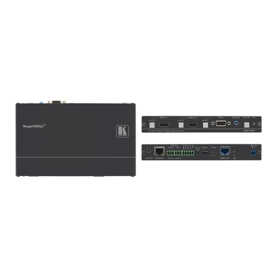
Page 7: Defining The Dip-20 Automatic Video Switcher
Press to take control of the input that this device is connected to on a compatible switcher ON LED The LED indicates the following: • Lights green—power is provided by a power adapter • Lights red—power is provided via PoE to another device DIP-20 – Defining the DIP-20 Automatic Video Switcher... - Page 8 Lights green when there is a valid HDBT link 48V DC Connector Connect to the supplied power adapter STEP IN Remote Toggle Switch Connect to a remote switch to activate the step in function Terminal Block DIP-20 – Defining the DIP-20 Automatic Video Switcher...
-
Page 9: Connecting The Dip-20 Automatic Video Switcher
Video Switcher Always switch off the power to each device before connecting it to your DIP-20. After connecting your DIP-20, connect the power to each of them and then switch on the power to each device. Figure 3: Connecting the DIP-20 You do not have to connect all the inputs and outputs, connect only those that are required. - Page 10 9. Connect the RS-232 DATA 3-pin terminal block to the device to be controlled, (for example, the projector connected in step 5). 10. Connect the power adapter to the DIP-20 and to the mains power, (not shown in Figure DIP-20 – Connecting the DIP-20 Automatic Video Switcher...
-
Page 11: Connecting The Remote Control Switches
This section defines the TP pinout, using a straight pin-to-pin cable with RJ-45 connectors. Figure 5: TP PINOUT EIA /TIA 568B Wire Color Orange / White Orange Green / White Blue Blue / White Green Brown / White Brown DIP-20 – Connecting the DIP-20 Automatic Video Switcher... -
Page 12: Principles Of Operation
Note: When “Audio Only” mode is enabled, analog audio is not output when there is no display connected. If a display is connected analog audio is output even in the absence of a video signal. DIP-20 – Principles of Operation... -
Page 13: Audio Signal Control
Each long press steps the phase shift up one step, starting from 0 and going to 31. When set to 31, another long press steps the shift to 0 • Using the Web pages, (see Accessing the DIP-20 Web Pages on page 15) • Protocol 3000 commands over RS-232 (see... -
Page 14: Operating The Dip-20
Connecting the Remote Control Switches on page 9) • Web pages, (see Operating the DIP-20 Remotely Using the Web Pages on page 15) Locking the EDID To prevent the stored EDID (either default or read from a device) from being overwritten, either send a Protocol 3000 command or use the Web pages. -
Page 15: Configuring The Dip-20
Embedded HDMI analog Audio In (high to low priority) Off (up) On (down) Automatic—Priority selection. Analog Audio In embedded HDMI (high to low priority) On (down) Off (up) Embedded HDMI On (down) On (down) Analog Audio In DIP-20 – Configuring the DIP-20... -
Page 16: Switching Timeouts
To be able to use the Step-in feature, you need to assign the RS-232 signal that is transmitted over the HDBT link to control (see Defining Control Settings on page 20). The Step-in button on the front panel will now operate in conjunction with a compatible receiver, for example, the VS-622DT). DIP-20 – Configuring the DIP-20... -
Page 17: Operating The Dip-20 Remotely Using The Web Pages
7) and you must enter the valid username and password to access the Web pages. For default authentication details, see Default Logon Credentials on page 32. Figure 7: Entering Logon Credentials DIP-20 – Operating the DIP-20 Remotely Using the Web Pages... - Page 18 Setting Authentication on page 26) • Managing EDID (see Managing EDID on page 27) • Upgrading Firmware (see Upgrading the Firmware on page 29) • About (see About Us on page DIP-20 – Operating the DIP-20 Remotely Using the Web Pages...
-
Page 19: Switching Input Signals
HDBT link to control (see Defining Control Settings on page 20). The Step-in button on the front panel now operates in conjunction with a compatible receiver, for example, the VS-622DT). DIP-20 – Operating the DIP-20 Remotely Using the Web Pages... -
Page 20: Setting Device Configurations
Reset the device to factory default settings Note: After making any change to the parameters on the Device Settings page, you must power cycle the device to activate the changes. Figure 10: Device Settings Page DIP-20 – Operating the DIP-20 Remotely Using the Web Pages... - Page 21 1. Click Save. The Save Configuration success message is displayed. 2. Click Download to either open the file or save it to the required location. Click OK to complete the procedure. DIP-20 – Operating the DIP-20 Remotely Using the Web Pages...
-
Page 22: Defining Control Settings
Remote Device Control over HDBaseT – Enables sending RS-232 commands over HDBaseT to turn on/off peripheral devices. When using this option, specify the predefined triggers (5V on – connect, 5V off – disconnect) with delays and default RS- 232 parameters. DIP-20 – Operating the DIP-20 Remotely Using the Web Pages... - Page 23 Use this section to select trigger conditions that initiate the power on/off actions Editor Use this section to edit information of the selected element Cancel Exit control settings without saving changes Save all Save the current configuration DIP-20 – Operating the DIP-20 Remotely Using the Web Pages...
- Page 24 2. In the Ports section, click the RS-232 port. The port information is displayed in the Editor: Figure 12: Editing an RS-232 Port 3. Edit the port information as necessary and click Save All. DIP-20 – Operating the DIP-20 Remotely Using the Web Pages...
- Page 25 Figure 13: Editing a Command 5. Optionally, edit the delay time before the command is triggered, click Test to test the command using the specified port, and click Save All. DIP-20 – Operating the DIP-20 Remotely Using the Web Pages...
- Page 26 Kramer Electronics Ltd. 6. In the Triggers section, select a trigger. The trigger information is displayed in the Editor: Figure 14: Editing a Trigger 7. Click Enabled. 8. Click Save All. DIP-20 – Operating the DIP-20 Remotely Using the Web Pages...
-
Page 27: Setting Video And Audio Parameters
Sets the delay for turning off the 5V output because of a signal loss on the upon signal loss for currently selected input. Value in seconds (see Signal Loss and Unplugged Cable Timeouts on page 10) DIP-20 – Operating the DIP-20 Remotely Using the Web Pages... -
Page 28: Setting Authentication
New password Enter the new password, (up to 15 printable ASCII characters) Retype New Retype the new password password box Change button Click Change to save the new authentication details DIP-20 – Operating the DIP-20 Remotely Using the Web Pages... -
Page 29: Managing Edid
When the status of an EDID changes on the device (caused by outputs being exchanged), the display is not updated automatically. In the browser, click Refresh to update the display. DIP-20 – Operating the DIP-20 Remotely Using the Web Pages... - Page 30 Note: An input must be connected to the device to read the EDID from a connected output. If a video signal is not detected on the input, the output is disabled and the EDID cannot be read. DIP-20 – Operating the DIP-20 Remotely Using the Web Pages...
-
Page 31: Upgrading The Firmware
5. When the process is complete reboot the device. The firmware is upgraded. You can upgrade firmware for multiple DIP-20 devices installed in the organization via Kramer Network. DIP-20 – Operating the DIP-20 Remotely Using the Web Pages... -
Page 32: About Us
Kramer Electronics Ltd. About Us DIP-20 About Us page displays the Web version and Kramer contact information. Figure 19: About Us Page DIP-20 – Operating the DIP-20 Remotely Using the Web Pages... -
Page 33: Technical Specifications
18.75cm x 11.5cm x 2.54cm (7.38” x 4.53” x 1.0”) W, D, H DIMENSIONS: WEIGHT: 0.46kg (1.01lbs) approx. SHIPPING WEIGHT: 1.16kg (2.56lbs) approx. ENVIRONMENTAL REGULATORY Complies with appropriate requirements of RoHs and WEEE COMPLIANCE: INCLUDED ACCESSORIES: Power adapter 48V DC 1.36A WARRANTY: 7 years parts and labor DIP-20 – Technical Specifications... -
Page 34: Default Ip Parameters
0 to 65535 5000 UDP Port 0 to 65535 50000 Default RS-232 Communication Parameters Parameter Values Baud Rate 11520 Data Bits Stop Bits Parity None Command Format ASCII Default Logon Credentials Parameter Values Name Admin Password Admin DIP-20 – Technical Specifications... -
Page 35: Supported Hdmi Resolutions
640x480p 60Hz 720x480p 60Hz 800x600p 60Hz 848x480p 60Hz 1024x768p 60Hz 1152x864 75Hz 1280x720p 60Hz; 50Hz 1280x768 60Hz 1280x800 60Hz 1280x960p 60Hz 1280x1024p 60Hz 1360x768 60Hz; 1366x768 60Hz; 50Hz 1400x1050 60Hz 1440x900 60Hz 1920x1080p 60Hz 1920x1200 60Hz DIP-20 – Technical Specifications... -
Page 36: Default Edid
1024 x 768p at 85Hz - VESA STD 800 x 600p at 85Hz - VESA STD 640 x 480p at 85Hz - VESA STD 1152 x 864p at 70Hz - VESA STD 1280 x 960p at 60Hz - VESA STD EIA/CEA-861 Information DIP-20 – Default EDID... - Page 37 Front left/right center.. No Rear left/right center... No Rear LFE....No Report information Date generated... 09/08/2015 Software revision..2.60.0.972 Data source....File Operating system..6.1.7601.2.Service Pack 1 Raw data 00,FF,FF,FF,FF,FF,FF,00,2D,B2,00,12,00,00,00,00,FF,19,01,03,80,34,20,78,EA,B3,25,AC,51,30,B4,26, 10,50,54,FF,FF,80,81,8F,81,99,A9,40,61,59,45,59,31,59,71,4A,81,40,01,1D,00,72,51,D0,1E,20,6E,28, 55,00,07,44,21,00,00,1E,00,00,00,FD,00,38,4C,1E,53,11,00,0A,20,20,20,20,20,20,00,00,00,FC,00,44, 49,50,2D,32,30,0A,20,20,20,20,20,20,02,3A,80,18,71,38,2D,40,58,2C,45,00,07,44,21,00,00,1E,01,A0, 02,03,1B,F1,23,09,07,07,48,10,05,84,03,02,07,16,01,65,03,0C,00,10,00,83,01,00,00,02,3A,80,18,71, 38,2D,40,58,2C,45,00,07,44,21,00,00,1E,01,1D,80,18,71,1C,16,20,58,2C,25,00,07,44,21,00,00,9E,01, 1D,00,72,51,D0,1E,20,6E,28,55,00,07,44,21,00,00,1E,8C,0A,D0,8A,20,E0,2D,10,10,3E,96,00,07,44,21, 00,00,18,00,00,00,00,00,00,00,00,00,00,00,00,00,00,00,00,00,00,00,00,00,00,00,00,00,00,00,00,47 DIP-20 – Default EDID...
-
Page 38: Pc-Uxga
640 x 480p at 85Hz - VESA STD 1152 x 864p at 70Hz - VESA STD 1280 x 960p at 60Hz - VESA STD Report information Date generated... 04/04/2019 Software revision..2.90.0.1020 Data source....File - NB: improperly installed DIP-20 – Default EDID... - Page 39 Kramer Electronics Ltd. Operating system..10.0.16299.2 Raw data 00,FF,FF,FF,FF,FF,FF,00,2D,B2,00,12,00,00,00,00,FF,19,01,03,6E,34,20,78,EE,B3,25,AC,51,30,B4,26, 10,50,54,FF,FF,80,81,8F,81,99,A9,40,61,59,45,59,31,59,71,4A,81,40,01,1D,00,72,51,D0,1E,20,6E,28, 55,00,07,44,21,00,00,1E,00,00,00,FD,00,38,4C,1E,53,11,00,0A,20,20,20,20,20,20,00,00,00,FC,00,44, 49,50,2D,32,30,0A,20,20,20,20,20,20,02,3A,80,18,71,38,2D,40,58,2C,45,00,07,44,21,00,00,1E,00,AF DIP-20 – Default EDID...
-
Page 40: Protocol 3000
You can enter commands directly using terminal communication software (e.g., Hercules) by connecting a PC to the serial or Ethernet port on the DIP-20. To enter CR press the Enter key (LF is also sent but is ignored by the command parser). -
Page 41: Understanding Protocol 3000
General syntax used for Protocol 3000 commands, see Kramer Protocol 3000 Syntax on page 40. • Protocol 3000 commands available for the DIP-20, see Protocol 3000 Commands on page 41. Understanding Protocol 3000 Protocol 3000 commands are structured according to the following: •... -
Page 42: Kramer Protocol 3000 Syntax
Kramer Electronics Ltd. Kramer Protocol 3000 Syntax The Kramer Protocol 3000 syntax uses the following delimiters: • CR = Carriage return (ASCII 13 = 0x0D) • LF = Line feed (ASCII 10 = 0x0A) • SP = Space (ASCII 32 = 0x20) Some commands have short name syntax in addition to long name syntax to enable faster typing. -
Page 43: Protocol 3000 Commands
Video Commands (see Video Commands on page 58) • Audio Commands (see Audio Commands on page 59) • Communication Commands (see Communication Commands on page 62) • EDID Handling Commands (see EDID Handling Commands on page 66) DIP-20 – Protocol 3000... -
Page 44: System Commands
Protocol handshaking Get: Response CR LF ~nn@ Parameters Response Triggers Notes Validates the Protocol 3000 connection and gets the machine number Step-in master products use this command to identify the availability of a device K-Config Example “#”,0x0D DIP-20 – Protocol 3000... - Page 45 Response Triggers Notes This command deletes all user data from the device. The deletion can take some time. Your device may require powering off and powering on for the changes to take effect. K-Config Example “#FACTORY”,0x0D DIP-20 – Protocol 3000...
- Page 46 – String of up to 19 printable ASCII chars Response Triggers Notes This command identifies equipment connected to Step-in master products and notifies of identity changes to the connected equipment. The Matrix saves this data in memory to answer REMOTE-INFO requests K-Config Example “#MODEL?”,0x0D DIP-20 – Protocol 3000...
- Page 47 To avoid locking the port due to a USB bug in Windows, disconnect USB connections immediately after running this command. If the port was locked, disconnect and reconnect the cable to reopen the port. K-Config Example “#RESET”,0x0D DIP-20 – Protocol 3000...
- Page 48 Transparency Set: VERSION? Get: End User Public Description Syntax Set: #VERSION?CR Get: Get firmware version number Response ~nn@VERSIONSPfirmware_versionCR LF Parameters firmware_version – XX.XX.XXXX where the digit groups are: major.minor.build version Response Triggers Notes K-Config Example “#VERSION?”,0x0D DIP-20 – Protocol 3000...
- Page 49 – for video layer: 1 (HDBT Out), for audio layer: 1 (Audio Out) mode – 0 (manual), 1 (priority switch), 2 (last connected switch) Response Triggers Notes K-Config Example Get the input audio switch mode for HDBT Out: “#AV-SW-MODE? 1,1”,0x0D DIP-20 – Protocol 3000...
- Page 50 The timeout for the disable 5V on video output if no input signal detected (4) event overlaps with the timeouts for all other events (0, 2, 5, 6). This does not apply to VGA input. K-Config Example Set the auto switching timeout to 5 seconds in the event of video signal lost: “#AV-SW-TIMEOUT 0,5”,0x0D DIP-20 – Protocol 3000...
- Page 51 Dp_sw_id – 1 (video switch), 2 (video switch), 3 (audio switch), 4 (audio switch) status – 0 (up / Off), 1 (down / On) Response Triggers Notes K-Config Example Get the status of DIP-switch 1 (video switch): “#DPSW-STATUS? 1”,0x0D DIP-20 – Protocol 3000...
- Page 52 (device button, device menu or other) or if the HDCP mode changed Notes Set HDCP working mode on the device input: HDCP not supported - HDCP Off HDCP support changes following detected sink - MIRROR OUTPUT K-Config Example Disable HDCP mode on HDMI In 2: “#HDCP-MOD 2,0”,0x0D DIP-20 – Protocol 3000...
- Page 53 The machine name is not the same as the model name. The machine name is used to identify a specific machine or a network in use (with DNS feature on). K-Config Example Set the DNS name of the device to “room-442”: “#NAME room-442”,0x0D DIP-20 – Protocol 3000...
- Page 54 PRIORITY2 - priority of Audio In: 1 (highest priority), 2 (second priority) Response Triggers Notes The number of PRIORITY parameters differs according to the selected layer 1 is the highest priority K-Config Example Set the video input priority of PC In as the highest priority: “#PRIORITY 1,2,3,1”,0x0D DIP-20 – Protocol 3000...
- Page 55 After execution, a response is sent to the com port from which the Get was received A response is sent after every change in input signal status from On to Off or from Off to On Notes K-Config Example Get the input signal lock status of HDMI In 2: “#SIGNAL? 2”,0x0D DIP-20 – Protocol 3000...
-
Page 56: Authentication Commands
The permission system works only if security is enabled with the SECUR command. It is not mandatory to enable the permission system in order to use the device K-Config Example Set the protocol permission level to Admin (when the password defined in the PASS command is 33333): “#LOGIN Admin,33333”,0x0D DIP-20 – Protocol 3000... - Page 57 – password for the login_level. Up to 15 printable ASCII chars. Response Triggers Notes The default password is an empty string K-Config Example Set the password for the Admin protocol permission level to 33333: “#PASS Admin,33333”,0x0D DIP-20 – Protocol 3000...
- Page 58 – 1 (On / enable security), 0 (Off / disable security) Response Triggers Notes The permission system works only if security is enabled with the SECUR command K-Config Example Enable the permission system: “#SECUR 0”,0x0D DIP-20 – Protocol 3000...
- Page 59 The set command is for remote input switching on Step-in clients (essentially via by the Web) K-Config Example Set the remote input switching of data to control mode: “#ROUTE 3,1,3”,0x0D Set the remote input switching of data to data mode: “#ROUTE 3,1,2”,0x0D DIP-20 – Protocol 3000...
-
Page 60: Video Commands
Set / Get: ~nn@VMUTESPoutput_id,flagCR LF Parameters output_id – 1 (HDBT Out) flag – 0 (disable video on output), 1 (enable video on output), 2 (blank video) Response Triggers Notes K-Config Example Disable the video output on HDBT Out: “#VMUTE 3,0”,0x0D DIP-20 – Protocol 3000... - Page 61 A response is sent to the com port from which the get command was received After execution, a response is sent to all com ports if AUD-EMB was set by any other external control device (button press, device menu and similar) Notes K-Config Example “#AUD-EMB? 1,1”,0x0D DIP-20 – Protocol 3000...
- Page 62 After execution, a response is sent to the com port from which the get command was received A response is sent to all com ports if the audio status was changed on any input Notes K-Config Example “#AUD-SIGNAL? 1”,0x0D DIP-20 – Protocol 3000...
- Page 63 #MUTE?SPchannelCR Get: Get audio mute Response ~nn@MUTESPchannel, mute_modeCR LF Parameters channel – audio output number: 1 (Audio Out) mute_mode – 0 (Off), 1 (On) Response Triggers Notes K-Config Example Mute the Audio Out output: “#MUTE 1,1”,0x0D DIP-20 – Protocol 3000...
-
Page 64: Communication Commands
If the port number you enter is already in use, an error is returned The port number must be within the following range: 0-(2^16-1) K-Config Example Set the Ethernet port protocol for TCP to port 12457: “#ETH-PORT TCP,12457”,0x0D DIP-20 – Protocol 3000... - Page 65 A network gateway connects the device via another network, possibly over the Internet. Be careful of security problems. Consult your network administrator for correct settings. K-Config Example Set the gateway IP address to 192.168.0.1: “#NET-GATE 192.168.000.001”,0x0D DIP-20 – Protocol 3000...
- Page 66 Set: NET-MAC? Get: End User Public Description Syntax Set: #NET-MAC?CR Get: Get MAC address Response ~nn@NET-MACSPmac_addressCR LF Parameters mac_address – unique MAC address. Format: XX-XX-XX-XX-XX-XX where X is hex digit Response Triggers Notes K-Config Example “#NET-MAC?”,0x0D DIP-20 – Protocol 3000...
- Page 67 Parameters net_mask - format: xxx.xxx.xxx.xxx Response Triggers The subnet mask limits the Ethernet connection within the local network Consult your network administrator for correct settings Notes K-Config Example Set the subnet mask to 255.255.0.0: “#NET-MASK 255.255.000.000”,0x0D DIP-20 – Protocol 3000...
- Page 68 Kramer Electronics Ltd. EDID Handling Commands Additional EDID data functions can be performed via the DIP-20 web pages or a compatible EDID management application, such as Kramer EDID Designer (see www.kramerav.com/product/DIP-20). Command Description CPEDID Copy EDID data from the output to the input EEPROM...
- Page 69 – 1 (HDMI In 1), 2 (HDMI In 2), 3 (PC In), lock_mode – 0 (Off: unlocks EDID), 1 (On: locks EDID) Response Triggers Notes K-Config Example Lock the last read EDID from the HDMI In 2 input: “#LOCK-EDID 2,1”,0x0D DIP-20 – Protocol 3000...
- Page 70 Electronics products, this product must be insured during shipment, with the insurance and shipping charges prepaid by you. If this product is returned uninsured, you assume all risks of loss or damage during shipment. Kramer Electronics will not be responsible for any costs related to the removal or re- installation of this product from or into any installation.
- Page 71 SAFETY WARNING Disconnect the unit from the power supply before opening and servicing For the latest information on our products and a list of Kramer distributors, visit our Web site where updates to this user manual may be found. We welcome your questions, comments, and feedback.
Need help?
Do you have a question about the DIP-20 and is the answer not in the manual?
Questions and answers