
Related Manuals for Kramer VP-558


Summary of Contents for Kramer VP-558
-
Page 1: User Manual
USER MANUAL MODEL: VP-558 Presentation Switcher/Scaler P/N: 2900-300433 Rev 3 www.kramerAV.com... -
Page 4: Table Of Contents
Figures Figure 1: VP-558 Presentation Switcher/Scaler Front Panel Figure 2: VP-558 Presentation Switcher/Scaler Rear Panel Figure 3: Connecting the VP-558 Presentation Switcher / Scaler Figure 4: Balanced Stereo Audio Connection Figure 5: Unbalanced Stereo Audio Output Connection Figure 6: balanced Stereo Audio Input Connection... - Page 5 Figure 12: The Loading Page Figure 13: Enter Username and Password Figure 14: The Switching Page Figure 15: The VP-558 Standby Mode Figure 16: The Switching Page – Input and Output Icons Figure 17: The Switching Page – Edit Output Buttons Figure 18: The Switching Page –...
-
Page 6: Introduction
Introduction Welcome to Kramer Electronics! Since 1981, Kramer Electronics has been providing a world of unique, creative, and affordable solutions to the vast range of problems that confront video, audio, presentation, and broadcasting professionals on a daily basis. In recent years, we have redesigned and upgraded most of our... -
Page 7: Getting Started
Avoid interference from neighbouring electrical appliances that may adversely influence signal quality Position your Kramer VP-558 away from moisture, excessive sunlight and dust This equipment is to be used only inside a building. It may only be connected to other equipment that is installed inside a building. -
Page 8: Safety Instructions
Kramer Electronics has made arrangements with the European Advanced Recycling Network (EARN) and will cover any costs of treatment, recycling and recovery of waste Kramer Electronics branded equipment on arrival at the EARN facility. For details of Kramer’s recycling arrangements in your particular country go to our recycling pages at http://www.kramerelectronics.com/support/recycling/. -
Page 9: Overview
(analog, digital and embedded audio are supported) on both HDMI and HDBaseT outputs. The VP-558 features 6 HDMI and 4 HDBaseT inputs as well as an analog VGA input and a 4x1 USB switcher. - Page 10 Remotely, from the infrared remote control transmitter with OSD (on−screen display) Via the Ethernet with built-in Web pages The VP-558 is housed in a 19” 2U rack mountable enclosure, with rack “ears” included, and is fed from a 100-240 VAC universal switching power supply. VP-558 – Overview...
-
Page 11: Using The Usb Switcher
Using the USB Switcher The VP-558 incorporates a simple, yet effective, 4:1 USB 1.1 switcher. The switcher can be used, for example, to connect one out of several PCs to a smart board or other USB client. The USB switcher can be routed as a separate layer, or can be tied to the video switching layer of the unit. -
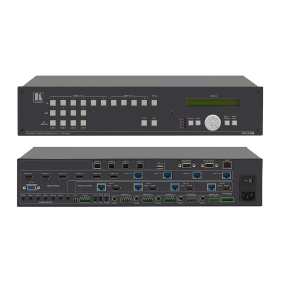
Page 12: Figure 1: Vp-558 Presentation Switcher/Scaler Front Panel
Figure 1: VP-558 Presentation Switcher/Scaler Front Panel Feature Function TO USB OUT Buttons Press a button to switch a USB input to the output (from USB 1 to USB 4) OUT Buttons Press a button to switch an input to up to 4 outputs... -
Page 13: Figure 2: Vp-558 Presentation Switcher/Scaler Rear Panel
Connectors PC IN 15-pin HD Connect to the computer graphics source Connect to an HDBT Transmitter (for example, the Kramer TP-580Txr) to pass audio and video signals as HDBT IN well as serial commands (from 1 to 4) USB (B type) IN Connectors... - Page 14 Connect to a stereo balanced audio acceptor (for example, active speakers or an audio power amplifier) Connectors VIDEO OUTPUT OUT (1 to 4) HDBT RJ-45 Connect to an HDBT Receiver (for example, the Kramer TP-580Rxr) Connectors HDMI Connect to an HDMI acceptor MONITOR OUT...
-
Page 15: Installing In A Rack
Installing in a Rack This section provides instructions for rack mounting the unit. VP-558 - Installing in a Rack... -
Page 16: Connecting The Vp-558
IN VIDEO INPUT connector (from 1 to 6). Alternatively, you can connect the DVI connector on the DVD player to the HDMI connector on the VP-558 via a DVI-HDMI adapter. When using this adapter, you can connect the audio signal via the terminal block connector 2. - Page 17 RS-232 CONTROL 9-pin D-sub Port to a PC to control the unit 10. Connect the MUTE 2-pin terminal block contact-closure remote-control pins to a switch to mute/unmute the audio output by momentarily pressing the switch. 11. Connect the ETHERNET port, see Section 6.6 VP-558 - Connecting the VP-558...
-
Page 18: Figure 3: Connecting The Vp-558 Presentation Switcher / Scaler
Figure 3: Connecting the VP-558 Presentation Switcher / Scaler VP-558 - Connecting the VP-558... -
Page 19: Connecting The Balanced Stereo Audio Input And Outputs
Connecting the Balanced Stereo Audio Input and Outputs Figure 4: Balanced Stereo Audio Figure 5: Unbalanced Stereo Audio Output Connection Connection Figure 7: Unbalanced Stereo Audio Input Figure 6: balanced Stereo Audio Input Connection Connection VP-558 - Connecting the VP-558... -
Page 20: Controlling The Vp-558
The ETHERNET (see Section 6.6) Controlling via the Front Panel Buttons The VP-558 includes the following front panel buttons: Input selector buttons for selecting the required input: HDMI (1 to 6), HDBT (1 to 4), or PC IN ... -
Page 21: Using The Osd Menu
Section 6.3). Using the OSD Menu The control buttons let you control the VP-558 via the OSD menu. Press the: OSD SELECT button to move through the outputs, until the led shows the output that you wish to use for controlling via the OSD ... -
Page 22: The Output 1 Menu
HDMI output) according to the HDCP of the input. This option is recommended when the HDMI output is connected to a splitter/switcher When FOLLOW OUTPUT is selected, the scaler matches its HDCP output to the HDCP setting of the HDMI acceptor to which it is connected VP-558 - Controlling the VP-558... - Page 23 BYPASS directly to the output. This feature can be used when the embedded input audio format is not supported by VP-558 (for example for Dolby or DTS formats), or when processing of the embedded input is not desired. Note that this function is irrelevant for the analog audio signals...
-
Page 24: The Osd Menu
Lock the MENU (and navigation) front panel buttons only ALL & SAVE Lock all the front panel buttons. The lock status is saved when the VP-558 is powered down MENU ONLY Lock the MENU (and navigation) front panel buttons & SAVE only. - Page 25 This feature can be used when the embedded input audio format is not supported by VP-558 (for example for Dolby or DTS formats), or when processing of the embedded input is not desired. Note that this function is irrelevant for the analog audio signals...
- Page 26 7.2.1). For example, set HDBT1 (IR OUT) to HDBT2 to control (via IR) the peripheral device that is connected to the device connected to HDBT 1 via the device connected to HDBT2, see Figure 28 VP-558 - Controlling the VP-558...
-
Page 27: The Main Menu For Outputs 2, 3 And 4
Source input Appears as: HDMI 1 HDMI1 HDBT 1 HDBT1 HDMI 2 HDMI2 HDBT 2 HDBT2 HDMI 3 HDMI3 HDBT 3 HDBT3 HDMI 4 HDMI4 HDBT 4 HDBT4 HDMI 5 HDMI5 PC IN HDMI 6 HDMI6 VP-558 - Controlling the VP-558... - Page 28 Turn the auto sync ON/OFF. When ON, this de-activates the output after a few minutes if no input is present. This is useful, for example, when the output is connected to a projector, and the projector will automatically shut down when it has no input VP-558 - Controlling the VP-558...
- Page 29 When ON, the VP-558 passes the embedded audio signal directly to the output. This feature can be used when the embedded input audio format is not supported by VP-558 (for example for Dolby or DTS formats), or when processing of the embedded input is not desired.
-
Page 30: Connecting To The Vp-558 Via Rs-232
Lock the MENU (and navigation) front panel buttons only ALL & SAVE Lock all the front panel buttons. The lock status is saved when the VP-558 is powered down MENU ONLY Lock the MENU (and navigation) front panel buttons only. -
Page 31: Operating Via The Ethernet
You can connect to the VP-558 via an RS-232 connection using, for example, a PC. Note that a null-modem adapter/connection is not required. To connect to the VP-558 via RS-232 Connect the RS-232 9-pin D-sub rear panel port on the product unit via a 9-wire straight cable (only pin 2 to pin 2, pin 3 to pin 3, and pin 5 to pin 5 need to be connected) to the RS-232 9-pin D-sub port on your PC. -
Page 32: Figure 8: Local Area Connection Properties Window
4. Highlight either Internet Protocol Version 6 (TCP/IPv6) or Internet Protocol Version 4 (TCP/IPv4) depending on the requirements of your IT system. 5. Click Properties. The Internet Protocol Properties window relevant to your IT system appears as shown in Figure 9 Figure VP-558 - Controlling the VP-558... -
Page 33: Figure 9: Internet Protocol Version 4 Properties Window
Figure 9: Internet Protocol Version 4 Properties Window Figure 10: Internet Protocol Version 6 Properties Window VP-558 - Controlling the VP-558... -
Page 34: Figure 11: Internet Protocol Properties Window
8. Click Close. 6.6.2 Connecting the Ethernet Port via a Network Hub or Switch You can connect the Ethernet port of the VP-558 to the Ethernet port on a network hub or using a straight-through cable with RJ-45 connectors. 6.6.3... -
Page 35: Using The Embedded Web Pages
Using the Embedded Web Pages The VP-558 can be operated remotely using the embedded Web pages. The Web pages are accessed using a Web browser and an Ethernet connection. Before attempting to connect: Perform the procedures in Section 6.6. -
Page 36: The Switching Page
The lower part of the screen lets you save the settings and upload a saved setting (see Section 7.11). The model name, FW version and IP number appear on the lower left side of the main page. VP-558 - Using the Embedded Web Pages... -
Page 37: Figure 14: The Switching Page
Figure 14: The Switching Page Click the power icon on the top right-hand side to toggle between normal operation and standby mode. When in standby mode, the icon appears dim: Figure 15: The VP-558 Standby Mode VP-558 - Using the Embedded Web Pages... -
Page 38: Figure 16: The Switching Page - Input And Output Icons
PC input does not have the Step-in icon. To edit an output button, select that button and click the edit icon. The output edit window appears: Figure 17: The Switching Page – Edit Output Buttons VP-558 - Using the Embedded Web Pages... -
Page 39: Figure 18: The Switching Page - Edit Hdmi/Hdbt Output
(see Section 6.3.3). Figure 19: The Switching Page –Edit Audio Output To edit an input button, select that button and click the edit icon. The input edit window appears: VP-558 - Using the Embedded Web Pages... -
Page 40: Figure 20: Edit Input Buttons
When selecting an HDMI input you can rename the input, set the embedded and analog audio volume and set HDCP to ON or OFF: Figure 21: Switching Page – HDMI input Window VP-558 - Using the Embedded Web Pages... -
Page 41: Figure 22: Switching Page - Hdbt Input Window
(see Section 7.2.1): Figure 22: Switching Page – HDBT input Window For HDBT inputs, when a Kramer SID-X2N unit is connected to an HDBT input, click the SID-X2N icon (see Figure 23) to open the SID-X2N setup window (see Figure 24). -
Page 42: Figure 25: Switching Page - Sid-X2N Setup Icon
The connection status indicator appears gray if the device is not connected, red if it is connected but without a valid signal and green if a signal is routed to the output. For HDMI inputs, when a Kramer SID-X3N unit is connected to an HDMI input, click the SID-X3N icon (see... -
Page 43: Figure 27: Switching Page - Pc Input Window
DVD remote control sends a command while pointing towards the External IR Sensor. The IR signal passes through the TP cables, the VP-558 and the IR Emitter to the DVD player, which responds to the command sent. At the same time you can... -
Page 44: Figure 28: Hdbt Ir Transmission Example
HDMI3 input. The output 2 button displays from HDMI3 next to the video icon. 3. Click the audio icon on the PC input. The Output 2 button displays PC next to the audio icon. VP-558 - Using the Embedded Web Pages... -
Page 45: The Scaler Page
Scaler page for output 1. Figure 29: The Scaler Page – Output 1 When PC IN is connected, the PC mode is enabled: Figure 30: The Scaler Page – Output 1 for the PC IN Input VP-558 - Using the Embedded Web Pages... -
Page 46: The Device Settings Page
Figure 31: The Scaler Page – Output 3 The Device Settings Page The Device Settings window (see Figure 32) lets you upgrade the firmware and set the Ethernet parameters. Figure 32: The Device Settings Page VP-558 - Using the Embedded Web Pages... -
Page 47: Figure 33: The Device Settings Page - Static Ip Confirmation
Figure 34: The Device Settings Page – Firmware Upgrade, Choosing a File Click the Upgrade button. The new firmware is uploaded: Figure 35: The Device Settings Page – Firmware Upgrade, Uploading the File VP-558 - Using the Embedded Web Pages... -
Page 48: Figure 36: The Device Settings Page - Firmware Upgrade Process
Figure 37: The Device Settings Page –Firmware Upgrade Complete Make sure that the new version appears on the Web page lower left side: Figure 38: The Device Settings Page – New Firmware Updated VP-558 - Using the Embedded Web Pages... -
Page 49: The Usb Routing Page
The USB page lets you select one of the USB hosts (buttons USB 1, USB 2, USB 3 or USB 4 – in the example in Figure 40, USB 1 is selected). The selected button is routed to the USB client. VP-558 - Using the Embedded Web Pages... -
Page 50: The Audio Settings Page
The rear panel DIP-switch settings (see Figure 2): Auxiliary Settings, Stereo/Mono and Microphone, are displayed. Note that the DIP-switch settings cannot be changed via the Web pages, but only physically on the rear panel. VP-558 - Using the Embedded Web Pages... -
Page 51: Figure 42: The Audio Settings Page - Inputs
You can set the delay time, the audio bypass and the audio source to switch to the output (automatic, embedded or analog), see Section 6.3: Figure 43: The Audio Settings Page – Output 1 VP-558 - Using the Embedded Web Pages... -
Page 52: Figure 44: The Audio Settings Page - Monitor
Monitor output equalizer settings as well as the volume of the AUX volume level and the speaker, Monitor and S/PDIF hardstop and volume levels: Figure 44: The Audio Settings Page – Monitor VP-558 - Using the Embedded Web Pages... -
Page 53: Figure 45: The Audio Settings Page - Mic Mixer
Talkover and set the mix level (MIC/LINE) if set to mixer. Figure 45: The Audio Settings Page – Mic Mixer VP-558 - Using the Embedded Web Pages... -
Page 54: The Edid Page
Figure 47 shows how to select a resolution from the list and select one or more inputs. To copy, click the Copy button: Figure 47: The EDID Page – Copying the Native Timing VP-558 - Using the Embedded Web Pages... -
Page 55: Figure 48: The Edid Page - Copying The Default
The EDID page displays the machine name, selected resolution, the audio channels and deep color support. After clicking the Copy button, the EDID page shows the copy EDID results: Figure 49: The EDID Page –The Copy EDID Results VP-558 - Using the Embedded Web Pages... -
Page 56: The Data Routing Page
SID-X2N/SID-X3N to the HDBaseT/HDMI input to which it is connected (see Figure 50 for example) Figure 50 shows the Routing tab and Figure 51 shows the Setting tab. Figure 50: The Data Routing Page –The Routing Tab VP-558 - Using the Embedded Web Pages... -
Page 57: Figure 51: The Data Routing Page -The Setting Tab
UDP Port: type the port number This way you can set the serial data in line with the serial data passed through. SID-X2N Data transfer: if the Kramer SID-X2N is connected to an HDBT port VP-558 - Using the Embedded Web Pages... -
Page 58: The Authentication Page
Authentication page: Figure 52: The Authentication Page 7.10 The About Page The VP-558 About page lets you view the Web page version and Kramer Electronics Ltd details. Figure 53: The About Page VP-558 - Using the Embedded Web Pages... -
Page 59: Save Or Upload A Configuration
7.11 Save or Upload a Configuration The VP-558 Web page lets you upload a saved configuration or save a configuration. To do so, click the Upload (see Figure 54) and Save buttons, respectively, which are located at the lower part of the menu list. -
Page 60: Technical Specifications
10% to 90%, RHL non-condensing DIMENSIONS: 19" x 14.4" x 2U (W, D, H) rack mountable WEIGHT: 5kg (11lbs) approx. INCLUDED ACCESSORIES: Power cord, rack ears Kramer BC−HDKat6a cable OPTIONS: Specifications are subject to change without notice at http://www.kramerelectronics.com VP-558 - Technical Specifications... -
Page 61: Default Communication Parameters
Maximum UDP/TCP Ports: Full Factory Reset Go to : Menu-> Factory-> RESET-ALL/RESET SCALER>Change the option to YES and press Enter (to complete the reset process you need to turn the power off and then on again) VP-558 - Technical Specifications... -
Page 62: Input Resolutions
1152x864 @75Hz 1280x720 @60Hz 1280x768 @60Hz 1280x800 @60Hz 1280x960 @60Hz 1280x1024 (@60/75Hz) 1360x768 @60Hz 1400x1050 @60Hz 1440x900 @60Hz 1600x900 RB @60Hz 1600x1200 @60Hz 1680x1050 RB @60Hz 1920x1080 @60Hz 1920x1200 RB @60Hz 480I/576I 480P/576P 720P(@50/60Hz) 1080I(@50/60Hz) 1080P(@24/30Hz) 1080P(@50/60Hz) VP-558 - Technical Specifications... -
Page 63: The Vp-558 Rs-232 Communication Protocol
The VP-558 RS-232 Communication Protocol The VP-558 can be operated using serial commands from a PC, remote controller, or touch screen. The unit communicates using the default Kramer Protocol 3000. Kramer Protocol 3000 syntax (see Section 9.1) Kramer Protocol 3000 command list (see Section 9.2) - Page 64 CRLF – For machine messages; carriage return (ASCII 13) + line-feed (ASCII 10) Command chain separator character When a message string contains more than one command, a pipe ( '|' ) character separates each command. Spaces between parameters or command terms are ignored. VP-558 - The VP-558 RS-232 Communication Protocol...
- Page 65 You can directly enter all commands using a terminal with ASCII communications software, such as HyperTerminal, Hercules, etc. Connect the terminal to the serial or Ethernet port on the Kramer device. To enter CR press the Enter key. ( LF is also sent but is ignored by command parser).
-
Page 66: Kramer Protocol 3000 - Command List
Set output resolution #VID-RES? Get input/output resolution #VMUTE Set video blank #VMUTE? Display video blank status #VFRZ Set video freeze #VFRZ? Display video freeze status #AUD-LVL Set audio level #AUD-LVL? Get audio level VP-558 - The VP-558 RS-232 Communication Protocol... - Page 67 Display UDP port #ETH-PORT TCP Set TCP port #ETH-PORT? TCP Display TCP port #HDCP-STAT? Display HDCP status #VOLUME Set global volume (+1 or -1) STANDBY Set Standby mode STANDBY? Get Standby mode status VP-558 - The VP-558 RS-232 Communication Protocol...
-
Page 68: Kramer Protocol 3000 - Detailed Commands
Output4 line Video Output HDBT3 Output4 SPDIF HDMI 1 HDBT4 HDBT 1 HDMI 2 HDBT 2 USB Host HDMI 3 USB 1 HDBT 3 USB 2 HDMI 4 USB 3 HDBT 4 USB 4 VP-558 - The VP-558 RS-232 Communication Protocol... - Page 69 1920x1080p@60 1280x768@60 1920x1080@60 1920x1080p@30 9.3.3 The Output Resolutions Key Resolution Resolution 640x480@60 1600x1200@60 800x600@60 1920x1080@60 1024x768@60 1920x1200@60RB 1280x768@60 720x480p@60 1360x768@60 1280x720p@60 1280x720@60 1920x1080p@60 1280x800@60 1920x1080i@60 1280x1024@60 720x576p@50 1440x900@60 1280x720p@50 1400x1050@60 1920x1080p@50 1680x1050@60 1920x1080i@50 VP-558 - The VP-558 RS-232 Communication Protocol...
- Page 70 (SID-X3N: select DP) same time) 2:Output2 1:3: HDMI1 3:Output3 (SID-X3N: select DVI) 4:Output4 1:4: HDMI1 5: All outputs (1~4) (SID-X3N: select PC) 2:1: HDMI2 (SID-X3N: select HDMI) 2:2: HDMI2 (SID-X3N: select DP) 2:3: HDMI2 VP-558 - The VP-558 RS-232 Communication Protocol...
- Page 71 2:Output2 2:1: HDMI2 Embedded 3:Output3 2:2: HDMI2 Analog 4:Output4 3:1: HDMI3 Embedded 3:2: HDMI3 Analog 4:1: HDMI4 Embedded 4:2: HDMI4 Analog 5:1: HDMI5 Embedded 5:2: HDMI5 Analog 6:1: HDMI6 Embedded 6:2: HDMI6 Analog VP-558 - The VP-558 RS-232 Communication Protocol...
- Page 72 2:1: HDMI2 Embedded analog 4: Output4 2:2: HDMI2 Analog 3:1: HDMI3 Embedded 3:2: HDMI3 Analog 4:1: HDMI4 Embedded 4:2: HDMI4 Analog 5:1: HDMI5 Embedded 5:2: HDMI5 Analog 6:1: HDMI6 Embedded 6:2: HDMI6 Analog VP-558 - The VP-558 RS-232 Communication Protocol...
- Page 73 Get command list or help for specific 2 options: command 1. #HELP␍ 2. #HELP␠command_name␍ Response 1. Multi-line: ~nn@Device available protocol 3000 commands:␍␊command,␠command…␍␊ To get help for command use : HELP (COMMAND_NAME) ␍␊ 2. Multi-line: ~nn@HELP␠command:␍␊description␍␊USAGE:usage ␍␊ VP-558 - The VP-558 RS-232 Communication Protocol...
- Page 74 Command Type – System-mandatory Command Name Permission Transparency Set: MODEL? Get: End User Description Syntax Set: Get : Get device model #MODEL?␍ Response ~nn@MODEL␠model_name␍␊ Parameters model_name – String of up to 19 printable ASCII chars VP-558 - The VP-558 RS-232 Communication Protocol...
- Page 75 To avoid locking the port due to a USB bug in Windows, disconnect USB connections immediately after running this command. If the port was locked, disconnect and reconnect the cable to reopen the port. VP-558 - The VP-558 RS-232 Communication Protocol...
- Page 76 Command Name Permission Transparency Set: NET-MAC? Get: End User Description Syntax Set: Get : Get MAC address #NET-MAC?␍ Response ~nn@NET-MAC␠mac_address␍␊ Parameters mac_address – Unique MAC address. Format: XX-XX-XX-XX-XX-XX where X is hex digit. VP-558 - The VP-558 RS-232 Communication Protocol...
- Page 77 Get: ~nn@ NET-GATE ␠ ip_address ␍␊ Parameters P1 (valid gate number)=xxx.xxx.xxx.xxx Notes A network gateway connects the device via another network and maybe over the Internet. Be careful of security problems. For proper settings consult your network administrator VP-558 - The VP-558 RS-232 Communication Protocol...
- Page 78 To connect with a randomly assigned IP by DHCP, specify the device DNS name (if available) using the command “NAME”. You can also get an assigned IP by direct connection to USB or RS-232 protocol port if available. For proper settings consult your network administrator. VP-558 - The VP-558 RS-232 Communication Protocol...
- Page 79 Response Triggers Response is sent to the com port from which the Set was received (before execution) Notes If different inputs are chosen, for example, HDMI1+HDMI6+HDBT1, then 61 should be set as parameter (1+32+64=97=0x61) VP-558 - The VP-558 RS-232 Communication Protocol...
- Page 80 ~nn@LDEDID␠ERR01␍␊ and returns to the regular protocol mode. If the unit received data that is not a correct packet, it sends the corresponding error and returns to the regular protocol mode. VP-558 - The VP-558 RS-232 Communication Protocol...
- Page 81 Response triggers After execution, response is sent to the com port from which the Get was received Response is sent after every change in input signal status ON to OFF, or OFF to ON VP-558 - The VP-558 RS-232 Communication Protocol...
- Page 82 Command Name Permission Transparency LOCK-FP Set: End User Get: LOCK-FP? End User Description Syntax Set: Lock front panel #LOCK-FP␠P1␍ Get : Get front panel lock state #LOCK-FP?␍ Response nn@LOCK-FP␠P1␠OK␍␊ Parameters P1 (Off/On)– 0=Off; 1=On VP-558 - The VP-558 RS-232 Communication Protocol...
- Page 83 After execution, response is sent to the com port from which the Set /Get was received After execution, response is sent to all com ports if VID-RES was set by any other external control device (button press, device menu and similar) VP-558 - The VP-558 RS-232 Communication Protocol...
- Page 84 After execution, response is sent to the com port from which the Set/Get was received After execution, response is sent to all com ports if VFRZ was set by any other external control device (button press, device menu and similar) VP-558 - The VP-558 RS-232 Communication Protocol...
- Page 85 #MIX␠ P1,P2 ␍ Set audio MIX Get : #MIX? ␠ P1 ␍ Get audio MIX Response ~nn@MIX␠ P1,P2 ␍␊ Parameters P1 (Output number) – 0=Audio out; 1=Output1; 2=Output2; 3=Output3; 4=Output4 P2 (Off/On)– 0=Off; 1=On VP-558 - The VP-558 RS-232 Communication Protocol...
- Page 86 After execution, response is sent to all com ports if CMD-NAME was set any other external control device (button press, device menu and similar) or genlock status was changed Notes Mutes the selected audio output VP-558 - The VP-558 RS-232 Communication Protocol...
- Page 87 After execution, response is sent to all com ports if CMD-NAME was set any other external control device (button press, device menu and similar) or genlock status was changed Notes Sets the image properties of the selected scaler VP-558 - The VP-558 RS-232 Communication Protocol...
- Page 88 After execution, response is sent to all com ports if CMD-NAME was set any other external control device (button press, device menu and similar) or genlock status was changed Notes Sets the audio delay for the selected audio output VP-558 - The VP-558 RS-232 Communication Protocol...
- Page 89 After execution, response is sent to all com ports if CMD-NAME was set any other external control device (button press, device menu and similar) or genlock status was changed Notes Sets the Microphone input audio gain VP-558 - The VP-558 RS-232 Communication Protocol...
- Page 90 Get: End User Public Description Syntax #ETH-PORT␠portType, ETHPort ␍ Set: Set Ethernet port protocol #ETH-PORT?␠portType ␍ Get: Get Ethernet port protocol Response ~nn@ ETH-PORT␠portType, ETHPort␍␊ Parameters portType - TCP/UDP ETHPort – TCP=5000-5099; UDP=50000-50999 VP-558 - The VP-558 RS-232 Communication Protocol...
- Page 91 P1 (Input/Output)– += increase current level; 1= decrease current level Notes To set / get an “input” level or audio level in other amplifier stage, use command #AUD-LVL / #AUD-LVL? to set / get audio level in specific amplifier stage VP-558 - The VP-558 RS-232 Communication Protocol...
- Page 92 Packet ID (1, 2, 3…) (2 bytes in length) Length (data length + 2 for CRC) - (2 bytes in length) Data (data length -2 bytes) CRC - 2 bytes 05… Packet ID Length Data VP-558 - The VP-558 RS-232 Communication Protocol...
- Page 93 Calculating the CRC The polynomial for the 16-bit CRC is: CRC-CCITT: 0x1021 = x Initial value: 0000 Final XOR Value: 0 For a code example, see: http://sanity-free.org/133/crc_16_ccitt_in_csharp.html CRC example: Data = “123456789” Result => 0x31C3 VP-558 - The VP-558 RS-232 Communication Protocol...
-
Page 95: Safety Warning
SAFETY WARNING Disconnect the unit from the power supply before opening and servicing For the latest information on our products and a list of Kramer distributors, visit our Web site where updates to this user manual may be found. We welcome your questions, comments, and feedback.
Need help?
Do you have a question about the VP-558 and is the answer not in the manual?
Questions and answers