Table of Contents
Advertisement
Quick Links
NETWORK ENABLED
ANTENNA & CABLE MONITOR
ACMI Series
Operation Manual
©Copyright 2019 by Bird Technologies, Inc.
Instruction Book P/N 920-ACMI Rev. D
Thruline® is a registered trademark of
Bird Electronic Corporation
Microsoft® are registered trademarks of the Microsoft Corporation
Oracle and Java are registered trademarks of Oracle and/or its affiliates.
Google and Google Chrome™ browser are registered trademarks of Google Inc.
Advertisement
Table of Contents

Related Manuals for BIRD ACMI Series


Summary of Contents for BIRD ACMI Series
- Page 1 NETWORK ENABLED ANTENNA & CABLE MONITOR ACMI Series Operation Manual ©Copyright 2019 by Bird Technologies, Inc. Instruction Book P/N 920-ACMI Rev. D Thruline® is a registered trademark of Bird Electronic Corporation Microsoft® are registered trademarks of the Microsoft Corporation Oracle and Java are registered trademarks of Oracle and/or its affiliates.
-
Page 2: Safety Precautions
Safety Precautions The following are general safety precautions that are not necessarily related to any specific part or procedure, and do not necessarily appear elsewhere in this publication. These precautions must be thoroughly understood and apply to all phases of operation and maintenance. WARNING Keep Away From Live Circuits Operating Personnel must at all times observe general safety precautions. -
Page 3: Safety Symbols
Safety Precautions Safety Symbols WARNING Warning notes call attention to a procedure, which if not correctly performed, could result in personal injury. CAUTION Caution notes call attention to a procedure, which if not correctly performed, could result in damage to the instrument. Note: Calls attention to supplemental information. -
Page 4: Warning Statements
ACMI Operation Manual Warning Statements The following safety warnings appear in the text where there is danger to operating and maintenance personnel, and are repeated here for emphasis. WARNING Leaking RF energy is a potential health hazard. Never attempt to connect or disconnect equipment from the transmission line while RF power is being applied. -
Page 5: Caution Statements
Safety Precautions Caution Statements The following equipment cautions appear in the text and are repeated here for emphasis. CAUTION The input voltage must be clean and stable. Be sure that the input voltage does not surge and does not contain spikes. Failure to comply may result in permanent damage to the instrument. -
Page 6: Safety Statements
ACMI Operation Manual Safety Statements USAGE ANY USE OF THIS INSTRUMENT IN A MANNER NOT SPECIFIED BY THE MANUFACTURER MAY IMPAIR THE INSTRUMENT’S SAFETY PROTECTION. EL USO DE ESTE INSTRUMENTO DE MANERA NO ESPECIFICADA POR EL FABRICANTE, PUEDE ANULAR LA PROTECCIÓN DE SEGURIDAD DEL INSTRUMENTO. - Page 7 Safety Precautions SERVICE SERVICING INSTRUCTIONS ARE FOR USE BY SERVICE - TRAINED PERSONNEL ONLY. TO AVOID DANGEROUS ELECTRIC SHOCK, DO NOT PERFORM ANY SERVICING UNLESS QUALIFIED TO DO SO. SERVICIO LAS INSTRUCCIONES DE SERVICIO SON PARA USO EXCLUSIVO DEL PERSONAL DE SERVICIO CAPACITADO. PARA EVITAR EL PELIGRO DE DESCARGAS ELÉCTRICAS, NO REALICE NINGÚN SERVICIO A MENOS QUE ESTÉ...
-
Page 8: About This Manual
ACMI Operation Manual About This Manual Sample Model ACMI–M–DMNFTL 470 – 960 MHz ACMI with male 7/16 input, female N output, female TNC monitor ports, requiring a low voltage power supply Base Frequency Range Monitor Port Power Supply RF Connectors Model (MHz) Connectors... -
Page 9: Changes To This Manual
About This Manual Changes to this Manual We have made every effort to ensure this manual is accurate. If you discover any errors, or if you have suggestions for improving this manual, please send your comments to our Solon, Ohio factory. This manual may be periodically updated. -
Page 10: Table Of Contents
Table of Contents Safety Precautions ......... i Safety Symbols . - Page 11 Table of Contents Panel Mount ........... 12 Installation .
-
Page 12: Chapter 1 Introduction
Chapter 1 Introduction Designed for 50 ohm coaxial transmission lines, the Bird Antenna & Cable Monitor is the solution for monitoring transmission antenna systems. Service providers and end users can rely on it to keep their critical sites up and running. -
Page 13: Items Supplied
Introduction Items Supplied ACMI Unit Instruction Manual Optional Accessories Note: for part numbers of See “Replacement Parts” on page 35. accessories. DB-15 Power/Alarm Cables — Connects the Antenna Monitor to a power supply and to external controllers. 50 feet long with male/female connectors. Note: Refer to for pin layout. -
Page 14: Component Description
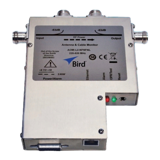
ACMI Operation Manual Component Description Figure 1 Antenna & Cable Monitor Outline RF Input Connects to the amplifier or combiner Forward Monitor Port Samples the forward traveling wave Reflected Monitor Port Samples the reflected wave RF Output Connects to the antenna or feeder Resets the alarm. - Page 15 Introduction Figure 2 Rack Mount Outline...
-
Page 16: Chapter 2 Theory Of Operation
Theory of Operation Alarm Response When an alarm is triggered, the Bird Antenna & Cable Monitor turns on the alarm LED and de-asserts a TTL logic line (pulls low). In addition, depending on configuration settings, one Form C dry contact relay changes state (i.e. activates or de-activates) as a result of the VSWR alarm activating. -
Page 17: Vswr Alarm
Theory of Operation VSWR Alarm The ACMI continuously monitors forward and reflected power. From the power measurements, the VSWR is calculated and compared to the allowed maximum (default of 1.5 to 1). Based on the results of the comparison, possible actions include: ... -
Page 18: Push-To-Talk
ACMI Operation Manual Push-to-Talk The low power alarm and the VSWR alarm can falsely trigger when the transmitter is not keyed. The Push-to-Talk feature disables alarm checking for a predetermined period after the Push-to-Talk logic line is asserted. In order to prevent false alarms while monitoring for low power and high VSWR, the Push- to-Talk feature must be enabled. -
Page 19: Chapter 3 Installation
Figure 3 on page 9 When connecting the Bird ACMI to RF power, use 50 ohm coaxial cable suitable for the frequency and power level of operation. The cable connector should mate with the connector on the unit. - Page 20 ACMI Operation Manual Connect the amplifier or combiner to the Monitor’s input. Connect the antenna or feeder to the output. WARNING Do not touch the center conductor of the power monitor ports while RF power is being applied. To monitor the RF waveform, connect the forward and reflected power monitor ports to an appropriate power sensor or meter.
-
Page 21: Power/Alarm Connector
Installation Power/Alarm Connector Note: The power cable must be <50m in length. Connect the external power supply here. Pin numbers and descriptions are given in Figure 4 If installing the ACMI in a Rack Mount Kit, a power supply is provided with the kit. -
Page 22: Pin Description
ACMI Operation Manual Figure 4 Voltage DB-15 Power/Alarm Connector, Female Description Relay 1, VSWR alarm contact, normally closed (closed when relay is not energized or loss of power to unit) (open when the relay is engaged) Relay 1, VSWR alarm common contact Alarm output, TTL compatible ... -
Page 23: Panel Mount
The +15V supply should only be used to power the ACMI Panel. Do not connect anything else to the power supply. Installation To install a Bird Antenna Monitor in the rack mount, follow these instructions (Refer to Figure 2 on page 4 1. - Page 24 ACMI Operation Manual CAUTION Network connections require specific address and protocol information. Have a qualified IT or network professional perform the ACMI Ethernet setup. Failure to comply may result in loss of network communication or the inability to communicate with the ACMI. The setup in this section should be performed only by a person who thoroughly understands IP and network setup protocols.
- Page 25 (JRE v7) or higher installed prior to connecting the ACMI to an Ethernet device. If you do not have the runtime environment, you can download it from the web at www.java.com or from the Bird Technology web site (www.birdrf.com). Note: It may be necessary to change the Java runtime environ- ment security level in order for the Web Tool to operate.
- Page 26 ACMI Operation Manual Figure 6 Ethernet Connection Flowchart...
- Page 27 Installation Note: The name you enter (at the left of the @ symbol) is also used in the ACMI Finder utility. If you use the email option to notify someone that an alarm has occurred, the name of this ACMI will help identify where the alarm came from.
- Page 28 ACMI Operation Manual Note: To use the features of the Web Tool, refer to "Operating Instructions" on page 19...
-
Page 29: Web Tool Software
Web browser that supports Java runtime environment version 7 (JRE v7) or higher such as Microsoft® Internet Explorer or Google Chrome™ Browser The ACMI Finder tool and JRE may be downloaded from the Bird Technologies Group website at: http://www.birdrf.com... -
Page 30: Chapter 4 Operating Instructions
Chapter 4 Operating Instructions Web Tool Software The ACMI Web Tool software is used to monitor the measurement outputs from the ACMI and to set and change alarm and network configurations. This software runs in a web browser (such as Microsoft’s Internet Explorer). To use the tool, open a web browser then in the address field, type the IP address of the ACMI you wish to access. -
Page 31: Stats Screen
Operating Instructions Figure 7 ACMI Web Tool Software, Main Screen Figure 8 Alarm Active Message Stats Screen The Stats screen ( ) can chart and display historical data Figure 13 on page 24 stored in the ACMI memory. You can chart forward and reflected power readings and alarm conditions (low power, high power, and VSWR alarm). -
Page 32: Data Log
ACMI Operation Manual Data Log The ACMI maintains a 365 day log (data log) of forward and reflected power readings and alarm conditions (low power, high power, and VSWR alarm). For each new day, the ACMI will automatically take a power reading every minute and average it with the previous minute. - Page 33 Operating Instructions Example - Comparing data from days 3-6 to days 203-206 on the same chart. You can view the days you've selected by scrolling the list to the right of the Add >> button under Day Selection. Note: The more days you view, the longer it will take to chart them.
- Page 34 ACMI Operation Manual Get Data 1. Click the Get Data button. Note: This will display the data for the current chart in a new win- dow in a tab-delimited text format. 2. Copy the text and paste it into a file on your computer or directly into a Microsoft Excel workbook.
-
Page 35: Config Screen
Operating Instructions Figure 13 Web Tool Stats Screen Config Screen The Config (Configure) screen sets alarm configuration and analog output gain. The administrator of the Web Tool can set an optional password requirement to control who can make changes to the Config screen. The Config password is disabled by default. - Page 36 ACMI Operation Manual VSWR Alarm Enable — Check the VSWR Alarm Enable box to monitor the VSWR reading and activate the alarm if the VSWR is slightly greater than the trip point for more than 30 seconds, or immediately if the VSWR is much greater than the Trip Point.
-
Page 37: Admin Screen
Operating Instructions Figure 14 Web Tool Config Screen, Alarms Admin Screen The Admin screen has four tabs, Network, Email Alerts, SNMP, and Passwords. After making changes in one or all of the tabs, click the Apply All Changes button to record your settings in memory. You must have a password to view and edit the Admin screen. - Page 38 ACMI Operation Manual Figure 15 Web Tool Admin Screen, Network Setup Email Alerts Tab In the Email Alerts tab ( ), you can specify the following Figure 16 on page 27 information: the SMTP server IP, the SMTP port, whether or not to use the email alerts, the email address of the ACMI, and the email addresses of two people to notify when an alarm occurs (optional).
- Page 39 Figure 17 on page 28 feature if you have chosen to use it. Contact your IT professional for assistance. You can obtain the latest MIB file from the Bird Technologies web site. Figure 17 Web Tool Admin Screen, Set SNMP Email Address...
-
Page 40: Help Screen
ACMI Operation Manual Help Screen While you are using the Web Tool software, you can access an on-line version of this manual by clicking on the Help button at the left side of the screen. Push-to-Talk When enabled, the Push-to-Talk (PTT) feature monitors the PTT logic input on the DB-15 connector. -
Page 41: Analog Output Gain
Operating Instructions Analog Output Gain This setting controls the sensitivity of the two analog outputs on the ACMI. The output level for the two channels are proportional to the measured power in the forward and reflected directions. The output range is 0 to 5.0 V with 10 bits of resolution. -
Page 42: Chapter 5 Maintenance
Chapter 5 Maintenance This chapter contains troubleshooting instructions, part information, and specifications for the Bird Antenna & Cable Monitor. Inspection and Cleaning This unit requires only simple and routine maintenance. CAUTION Do not use harsh or abrasive detergents for cleaning. -
Page 43: Troubleshooting
Maintenance Troubleshooting The Bird Antenna Monitor has no operator serviceable parts. Any required service must be performed at an authorized service facility. The table below contains troubleshooting information for problems which can occur during normal operation. This manual cannot list all malfunctions that may occur, or their corrective actions. -
Page 44: Specifications
ACMI Operation Manual Specifications General Directivity, Min. 108 – 960 MHz 30 dB 960 – 2400 MHz 26 dB 1.3:1.0 to 2.5:1.0 by 0.1:1.0 steps. Refer to VSWR Alarm Setpoint "Power/Alarm Connector" on page 10 information about power limitations. Dry, form C. Common, normally open, & Alarm Relays normally closed contacts. -
Page 45: Frequency Range
Maintenance Weight, Max. 2 lbs. (0.9 kg) Frequency Range ACMI500 ACMI L0-xxxxxx 108 – 144 MHz L1-xxxxxx 136 – 225 MHz L2-xxxxxx 225 – 520 MHz M-xxxxxx 470 – 960 MHz H-xxxxxx 960 – 2400 MHz RF Power Range ACMI-xx-xxxxxx 2.5 –... -
Page 46: Safety
ACMI Operation Manual 7/16 DIN Connectors 108 - 960 MHz 1.07:1 960 - 2000 MHz 1.1:1 2000 - 2400 MHz 1.2:1 Safety Directive 2004/108/EC relating to electromagnetic compatibility EN 61326-1 - Electrical equipment for measurement, control and laboratory use - EMC requirements - Part 1: General requirements (IEC 61326-1): Radiated Immunity (EN 61000-4-3) -
Page 47: Limited Warranty
Limited Warranty All products manufactured by Seller are warranted to be free from defects in material and workmanship for a period of one (1) year, unless otherwise specified, from date of shipment and to conform to applicable specifications, drawings, blueprints and/or samples. Seller’s sole obligation under these warranties shall be to issue credit, repair or replace any item or part thereof which is proved to be other than as warranted;...
Need help?
Do you have a question about the ACMI Series and is the answer not in the manual?
Questions and answers