Table of Contents
Advertisement
Quick Links
TEL:0755-88851600
FAX:0755-88850158
深圳市朗普电子科技有限公司
深圳市朗普电子科技有限公司
E-mail:df@17Lp.com Lp@Lp-17.com
INSTRUCTION BOOK
OPERATING INSTRUCTIONS
MULTI-PURPOSE
THRULINE
RF POWER ANALYST
MODEL 4391A
Thruline® and Power Analyst® are Registered Trademark of
http://www.17Lp.com
WATTMETER
®
©Copyright 2008 by Bird Electronic Corporation
Instruction Book Part Number 920-4391A Rev. H
TEL:0755-88851600
FAX:0755-88850158
®
Bird Electronic Corporation
Advertisement
Table of Contents

Related Manuals for BIRD THRULINE RF POWER ANALYST 4391A


Summary of Contents for BIRD THRULINE RF POWER ANALYST 4391A
- Page 1 OPERATING INSTRUCTIONS MULTI-PURPOSE THRULINE WATTMETER ® RF POWER ANALYST ® 深圳市朗普电子科技有限公司 MODEL 4391A ©Copyright 2008 by Bird Electronic Corporation Instruction Book Part Number 920-4391A Rev. H Thruline® and Power Analyst® are Registered Trademark of Bird Electronic Corporation TEL:0755-88851600 深圳市朗普电子科技有限公司 FAX:0755-88850158...
-
Page 2: Safety Precautions
TEL:0755-88851600 http://www.17Lp.com FAX:0755-88850158 E-mail:df@17Lp.com Lp@Lp-17.com Safety Precautions The following are general safety precautions that are not necessarily related to any specific part or procedure, and do not necessarily appear elsewhere in this publication. These precautions must be thoroughly understood and apply to all phases of operation and maintenance. Keep Away From Live Circuits Operating personnel must at all times observe normal safety regulations. - Page 3 TEL:0755-88851600 http://www.17Lp.com Bird Model 4391M Power Analyst FAX:0755-88850158 E-mail:df@17Lp.com Lp@Lp-17.com CAUTION Caution notes call attention to a procedure which, if not correctly performed, could result in damage to the instrument. The caution symbol appears on the equipment indicating there is important information in the instruction manual regarding that particular area.
- Page 4 TEL:0755-88851600 http://www.17Lp.com FAX:0755-88850158 E-mail:df@17Lp.com Lp@Lp-17.com Caution Statements The following equipment cautions appear in the text whenever the equipment is in danger of damage, and are repeated here for emphasis. CAUTION Long-term storage of this instrument can affect battery performance and reduce battery life.
- Page 5 TEL:0755-88851600 http://www.17Lp.com Bird Model 4391M Power Analyst FAX:0755-88850158 E-mail:df@17Lp.com Lp@Lp-17.com Safety Statements USAGE ANY USE OF THIS INSTRUMENT IN A MANNER NOT SPECIFIED BY THE MANUFACTURER MAY IMPAIR THE INSTRUMENT’S SAFETY PROTECTION. EL USO DE ESTE INSTRUMENTO DE MANERA NO ESPECIFICADA POR EL FABRICANTE, PUEDE ANULAR LA PROTECCIÓN DE SEGURIDAD...
- Page 6 TEL:0755-88851600 http://www.17Lp.com FAX:0755-88850158 E-mail:df@17Lp.com Lp@Lp-17.com PRÉVENIR UN CHOC ÉLECTRIQUE DANGEREUX, NE PAS EFFECTUER D’ENTRETIEN SI L’ON N’A PAS ÉTÉ QUALIFIÉ POUR CE FAIRE. UNITS ARE EQUIPPED WITH RECHAREABLE BATTERIES. THESE ARE TO BE REPLACED BY AUTHORIZED SERVICE PERSONNEL ONLY!!! LAS UNIDADES VIENEN EQUIPADAS CON BATERIAS RECARGABLES.
- Page 7 TEL:0755-88851600 http://www.17Lp.com Bird Model 4391M Power Analyst FAX:0755-88850158 E-mail:df@17Lp.com Lp@Lp-17.com PRIMA DI EROGARE CORRENTE, ASSICURARSI CHE IL SELETTORE DI VOLTAGGIO 115/230 V.C.A. SIA REGOLATO CORRETTAMENTE E CHE IL FUSIBLE ADATTO ALLA LINEA DI ALIMENTAZIONE C.A. SIA INSTALLATO. RF VOLTAGE MAY BE PRESENT IN RF ELEMENT SOCKET - KEEP ELEMENT IN SOCKET DURING OPERATION.
-
Page 8: About This Manual
TEL:0755-88851600 http://www.17Lp.com FAX:0755-88850158 E-mail:df@17Lp.com Lp@Lp-17.com About This Manual This instruction book is arranged so that essential information on safety is contained in the front of the book. Reading the Safety Precautions Section before operating the equipment is strongly advised. The remainder of this manual is divided into Chapters and Sections. Figures and tables are numbered sequentially within each chapter. - Page 9 TEL:0755-88851600 http://www.17Lp.com Bird Model 4391M Power Analyst FAX:0755-88850158 E-mail:df@17Lp.com Lp@Lp-17.com 深圳市朗普电子科技有限公司 TEL:0755-88851600 viii 深圳市朗普电子科技有限公司 FAX:0755-88850158...
-
Page 10: Table Of Contents
TEL:0755-88851600 http://www.17Lp.com FAX:0755-88850158 E-mail:df@17Lp.com Lp@Lp-17.com Table of Contents Safety Precautions ......i About This Manual ......vii Introduction . - Page 11 TEL:0755-88851600 http://www.17Lp.com FAX:0755-88850158 E-mail:df@17Lp.com Lp@Lp-17.com Troubleshooting ......23 General......23 Disassembly .
-
Page 12: Introduction
TEL:0755-88851600 http://www.17Lp.com FAX:0755-88850158 E-mail:df@17Lp.com Lp@Lp-17.com Chapter 1 Introduction The Model 4391A is a multi-purpose Radio Frequency wattmeter designed around a microcomputer. A program stored in permanent memory controls the operation of the instrument at all times, permitting the detection and correction of various error sources and the refinement of the raw data produced by the directional detectors. -
Page 13: Description
4 inches wide (111 mm x 244 mm x 159 mm) including connections, see Figure 1. At each end of the line section are Bird Quick-Change type RF connectors which may be easily interchanged with any other Bird QC connector. See Bird Catalog for types available. -
Page 14: Theory Of Operation
TEL:0755-88851600 http://www.17Lp.com FAX:0755-88850158 E-mail:df@17Lp.com Lp@Lp-17.com Chapter 2 Theory of Operation Figure 2 is a block diagram of the major functional parts of Description of the Model 4391A RF Wattmeter. The Microcomputer Operation integrated circuit shown, controls all the other portions of the instrument, which fall into two major groups. - Page 15 TEL:0755-88851600 http://www.17Lp.com Bird Model 4391A Power Analyst FAX:0755-88850158 E-mail:df@17Lp.com Lp@Lp-17.com Each reading output by the display is derived from up to three voltage readings using the circuitry described above. Once these voltages are measured, all remaining operations are performed within the computer chip as follows: The voltages are corrected for error due to dc drift in the analog circuitry.
- Page 16 TEL:0755-88851600 http://www.17Lp.com Theory of Operation FAX:0755-88850158 E-mail:df@17Lp.com Lp@Lp-17.com The electrical values of the element circuits are carefully balanced and designed so that current from the reverse wave will cancel the other almost completely. The result is directivity always higher than 25 dB, which means that the element is highly insensitive (nulled) to the REVERSE direction wave.
- Page 17 TEL:0755-88851600 http://www.17Lp.com Bird Model 4391A Power Analyst FAX:0755-88850158 E-mail:df@17Lp.com Lp@Lp-17.com 深圳市朗普电子科技有限公司 TEL:0755-88851600 深圳市朗普电子科技有限公司 FAX:0755-88850158...
-
Page 18: Installation
TEL:0755-88851600 http://www.17Lp.com FAX:0755-88850158 E-mail:df@17Lp.com Lp@Lp-17.com Chapter 3 Installation The Model 4391A RF Power Analyst is completely portable and very suitable for field or laboratory use. Its power is derived from rechargeable nickel metal hydride batteries inside the unit or from an AC outlet via the power cord supplied with the device. -
Page 19: Connections
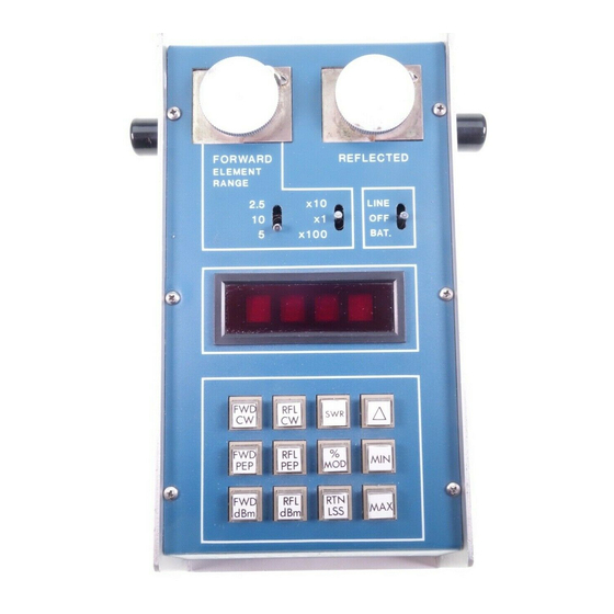
TEL:0755-88851600 http://www.17Lp.com Bird Model 4391A Power Analyst FAX:0755-88850158 E-mail:df@17Lp.com Lp@Lp-17.com The Model 4391A contains a short section of rigid 50 ohm Connections coaxial air dielectric transmission line. To make measurements relating to the travelling waves in a coaxial line, that line must be disconnected at some convenient point to permit the Model 4391A air line to be inserted. - Page 20 TEL:0755-88851600 http://www.17Lp.com Installation FAX:0755-88850158 E-mail:df@17Lp.com Lp@Lp-17.com with the nominal power range of the elements. For example, if the forward element is a 5 watt element, the switches are set at 5 and x1. For a 250 watt element they are set at 2.5 and x100.
- Page 21 TEL:0755-88851600 http://www.17Lp.com Bird Model 4391A Power Analyst FAX:0755-88850158 E-mail:df@17Lp.com Lp@Lp-17.com 深圳市朗普电子科技有限公司 TEL:0755-88851600 深圳市朗普电子科技有限公司 FAX:0755-88850158...
-
Page 22: Operating Instructions
The Model 4391A arrives at values of CW power by a method quite different from analog meters such as the Model 43, also manufactured by Bird Electronic. While the two instruments will agree when the measured wave is of constant amplitude, AM or SSB waves will result in different indications (in the CW mode). -
Page 23: Reading Reflected Cw Power
TEL:0755-88851600 http://www.17Lp.com Bird Model 4391A Power Analyst FAX:0755-88850158 E-mail:df@17Lp.com Lp@Lp-17.com signal coming from the element, whereas the Model 4391A uses peak and negative peak detector circuits to measure peak and minimum square root of power and combines them using the equation:... -
Page 24: Measuring Peak Envelope Power
TEL:0755-88851600 http://www.17Lp.com Operating Instructions FAX:0755-88850158 E-mail:df@17Lp.com Lp@Lp-17.com Table 2 VSWR Return Reflected VSWR Return Reflected Voltage Loss Power % Loss Power % Standing (dB) (dB) Wave Ratio 1.01 46.1 0.00 1.45 14.7 3.37 (VSWR) 1.02 40.1 0.01 1.50 14.0 4.00 1.03 36.6 0.02... -
Page 25: Measuring Amplitude Modulation
TEL:0755-88851600 http://www.17Lp.com Bird Model 4391A Power Analyst FAX:0755-88850158 E-mail:df@17Lp.com Lp@Lp-17.com Only a forward element is required for this mode. Point the Measuring element in the direction of forward power and press % MOD. Amplitude Modulation is displayed directly in percent, provided the... -
Page 26: Measuring Power In Dbm
TEL:0755-88851600 http://www.17Lp.com Operating Instructions FAX:0755-88850158 E-mail:df@17Lp.com Lp@Lp-17.com Operation of the forward and reflected dBm modes is Measuring identical to the forward and reflected CW power modes, Power in dBm except that the resulting reading is converted to dB above 1 milliwatt before it is displayed. -
Page 27: Insertion Loss Or Attenuation
TEL:0755-88851600 http://www.17Lp.com Bird Model 4391A Power Analyst FAX:0755-88850158 E-mail:df@17Lp.com Lp@Lp-17.com Attenuation or insertion loss can be measured directly using Insertion an external single port line section (P/N 4230-006-1), a dc Loss or feed-in adapter (P/N 4381-050), and a dc cable (P/N 3170- Attenuation 058-6). -
Page 28: Monitoring Maximum And Minimum Readings 16 Using The Peaking Aid
TEL:0755-88851600 http://www.17Lp.com Operating Instructions FAX:0755-88850158 E-mail:df@17Lp.com Lp@Lp-17.com Figure 13 Maximum or Minimum Readings The peaking aid is useful for making adjustments to Using the optimize any of the parameters which the Model 4391A Peaking Aid ∆ measures. After the mode is selected, press the delta ( ) key momentarily. -
Page 29: Battery Care
TEL:0755-88851600 http://www.17Lp.com Bird Model 4391A Power Analyst FAX:0755-88850158 E-mail:df@17Lp.com Lp@Lp-17.com With average use, the nickel metal hydride batteries in the Battery Care 4391A will power the unit for 12 hours before needing recharged. The 4391A will maintain rated accuracy until all the decimal points light, indicating that recharging is required. -
Page 30: Maintenance
TEL:0755-88851600 http://www.17Lp.com FAX:0755-88850158 E-mail:df@17Lp.com Lp@Lp-17.com Chapter 5 Maintenance The 4391A RF Power Analyst was designed and built to provide many years of trouble free service. This section provides the information needed to prevent and correct equipment failure. Preventive Maintenance To avoid unnecessary damage, always observe the following cautions: The RF Power Analyst is a rugged and portable instru- ment intended for field use. -
Page 31: Calibration
Equipment Cable Assembly (1 Required) BNC to BNC (1 meter long) DC Feed-in Element (1 required) Bird Electronic 4381-050 On a clean flat workspace perform the following setup Initial Setup procedure: Remove the front panel. Refer to “Front Panel Removal”... -
Page 32: Element Wiper Contact Adjustment
TEL:0755-88851600 http://www.17Lp.com Maintenance FAX:0755-88850158 E-mail:df@17Lp.com Lp@Lp-17.com Switch on the Calibrator/Source and let it warm up for at least one hour. Set the Calibrator/Source to output 30 ±0.05 microamps. Adjust potentiometer, R25 (Figure 15, page 21), until the RF Power Analyst Displays 1000 ±5. Figure 15 Calibration Potentiometer... - Page 33 TEL:0755-88851600 http://www.17Lp.com Bird Model 4391A Power Analyst FAX:0755-88850158 E-mail:df@17Lp.com Lp@Lp-17.com Perform the following steps to adjust the contact spring. 1. Using a small flat head screwdriver, place the flat side of the screwdriver behind the contact bar as indicated and bend the contact bar so that the contact rests in the center of the slot adjacent to the element socket (Figure 16).
-
Page 34: Troubleshooting
TEL:0755-88851600 http://www.17Lp.com Maintenance FAX:0755-88850158 E-mail:df@17Lp.com Lp@Lp-17.com Troubleshooting The troubleshooting instructions are intended to aid in fault General isolation. This is accomplished through the use of a troubleshooting table. First, locate the symptom(s) in the problem column of Table 8. In some cases the same fault can have more than one symptom and more than one possible remedy. -
Page 35: Disassembly
TEL:0755-88851600 http://www.17Lp.com Bird Model 4391A Power Analyst FAX:0755-88850158 E-mail:df@17Lp.com Lp@Lp-17.com PROBLEM POSSIBLE CAUSE REMEDY Display Element wiper not Readjust the element wiper to indicates “0” contacting the element make good contact (page 21). Power Defective Plug-in Replace Plug-In Element. Element... -
Page 36: Main Printed Circuit (Pc) Board Removal
TEL:0755-88851600 http://www.17Lp.com Maintenance FAX:0755-88850158 E-mail:df@17Lp.com Lp@Lp-17.com Lift the front panel from the housing. Be careful to clear the line section blocks. Remove pads from the three toggle switches. Figure 18 Removing Front Panel 深圳市朗普电子科技有限公司 Remove the front panel (Refer to “Front Panel Removal” Main Printed on page 24) Circuit (PC) -
Page 37: Qc Connectors Removal
TEL:0755-88851600 http://www.17Lp.com Bird Model 4391A Power Analyst FAX:0755-88850158 E-mail:df@17Lp.com Lp@Lp-17.com Figure 19 Removing Main PCB 深圳市朗普电子科技有限公司 Remove the eight screws (four on each connector) that secure the connectors to the housing (Figure 20, item 1). Connectors Removal Remove the two “QC” connectors (item 2) by pulling them away from the line section assembly. -
Page 38: Line Section Removal
TEL:0755-88851600 http://www.17Lp.com Maintenance FAX:0755-88850158 E-mail:df@17Lp.com Lp@Lp-17.com Remove the QC connectors (page 26). Line Section Removal Remove the four screws and lock washers that secure line section assembly to the housing (item 3). Using minimum pressure, spread apart the sides of the lower housing assembly just far enough to allow the line section assembly to be removed. -
Page 39: Battery Replacement
TEL:0755-88851600 http://www.17Lp.com Bird Model 4391A Power Analyst FAX:0755-88850158 E-mail:df@17Lp.com Lp@Lp-17.com Remove the two screws (item 4) that secure the PCB to the line section then pull the PC board assembly (item 3) away from the line section subassembly. Remove the spacers (item 2). - Page 40 TEL:0755-88851600 http://www.17Lp.com Maintenance FAX:0755-88850158 E-mail:df@17Lp.com Lp@Lp-17.com Lower and secure the Main PC board assembly Replace and secure the front cover. 10. Charge the batteries for 16 hours before using the instrument. Figure 22 Tilt Main PCB to Expose Batteries Figure 23 Battery 深圳市朗普电子科技有限公司...
-
Page 41: Parts List
TEL:0755-88851600 http://www.17Lp.com Bird Model 4391A Power Analyst FAX:0755-88850158 E-mail:df@17Lp.com Lp@Lp-17.com Parts List This section contains an illustrated list of all authorized replacement parts for the 4391A RF power Analyst. Parts are grouped into major assemblies and subassemblies. Figure 24 Parts Drawing 深圳市朗普电子科技有限公司... - Page 42 TEL:0755-88851600 http://www.17Lp.com Maintenance FAX:0755-88850158 E-mail:df@17Lp.com Lp@Lp-17.com Figure 25 Line Section Assembly (S/N 1723 and below) 深圳市朗普电子科技有限公司 Item No. Description Part No. Figure 25 Line Section, Subassembly 4381-005 PC Board, Data Acquisition Assy 4391A006 Bead, Keying 4391-026 Spacer 4391-027 Screw, Machine, filister head, COML No.
- Page 43 TEL:0755-88851600 http://www.17Lp.com Bird Model 4391A Power Analyst FAX:0755-88850158 E-mail:df@17Lp.com Lp@Lp-17.com Figure 26 Line Section Assembly (S/N 1724 and above) 深圳市朗普电子科技有限公司 Part No. Description Part No. Figure 26 Line Section, Subassembly 4381-005 PC Board, Data Acquisition Assy 4391A006 Bead, Keying 4391-026...
-
Page 44: Customer Service
If you need to return the unit for any reason, contact the Bird Service Center for a return authorization. All instruments returned must be shipped prepaid and to the attention of Bird Service Center. -
Page 45: Specifications
Weight 5-3/4 lb (2.6 kg) Frequency band and power range is determined by the Plug-in Elements select- ed. See Bird Catalog for availability. Some modes require two elements in a 10:1 power ratio. † VSWR and return loss functions settle in less than 1 second. - Page 46 TEL:0755-88851600 http://www.17Lp.com FAX:0755-88850158 E-mail:df@17Lp.com Lp@Lp-17.com Limited Warranty All products manufactured by Seller are warranted to be free from defects in material and workmanship for a period of one (1) year, unless otherwise specified, from date of shipment and to conform to applicable specifications, drawings, blueprints and/or samples.
Need help?
Do you have a question about the THRULINE RF POWER ANALYST 4391A and is the answer not in the manual?
Questions and answers