Series 4410 Directional RF
Thruline® Wattmeter
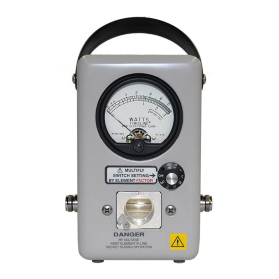
Model 4410S
Operation Manual
©Copyright 2016 by Bird Electronic Corporation
Instruction Book Part Number 920-4410S Rev. G
Thruline
and
trademarks
®
Termaline® are Registered
of Bird Electronic Corporation


Need help?
Do you have a question about the 4410 Series and is the answer not in the manual?
Questions and answers